Table of Contents
Advertisement
Quick Links
Hacousto Holland bv
Industrieweg 87
2651BC Berkel & Rodenrijs
CONTROLLER user manual
SUMMARY
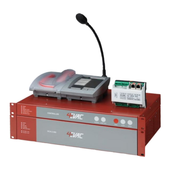
This document is the user and installation manual of the 4EVAC Controller, the head unit of the 4EVAC
Impact voice evacuation system.
REVISION AND APPROVAL
Rev.
Date
01
05-06-2019
02
10-03-2020
03
08-06-2020
04
11-06-2020
Nature of Changes
Original draft
Updated CAL button, GPO rating, # of zones, net ports,
max. output power, # of DCA amplifiers, # of messages
Corrections
Minor corrections
Page 1 of 14
Author:
Approved By
DD
DD
TvdH
DD
DD
Advertisement
Table of Contents

Related Manuals for 4EVAC IMPACT


Summary of Contents for 4EVAC IMPACT
- Page 1 Hacousto Holland bv Industrieweg 87 2651BC Berkel & Rodenrijs Author: CONTROLLER user manual SUMMARY This document is the user and installation manual of the 4EVAC Controller, the head unit of the 4EVAC Impact voice evacuation system. REVISION AND APPROVAL Rev. Date Nature of Changes...
-
Page 2: Table Of Contents
Hacousto Holland bv Industrieweg 87 2651BC Berkel & Rodenrijs Author: CONTROLLER user manual Table of Contents General information ................................3 Front indicators ..................................3 POWER ................................... 3 EVAC ....................................4 GENERAL FAULT ................................4 POWER SUPPLY FAULT ............................. 4 SYSTEM FAULT ................................4 NETWORK FAULT ................................ -
Page 3: General Information
BGM broadcasts, microphone consoles, I/O extensions and cabling infrastructure. 1. General information 4EVAC Controller is the head unit of the 19” rack mounted Impact Voice Evacuation System. The Controller covers complete EN54-16 certified functionality, as well as a variety of features essential to Public Address applications. -
Page 4: Evac
(this Impact controller and amplifiers are healthy and another device in the network is reporting fault state) POWER SUPPLY FAULT Indicates a power supply fault of the local Impact system, where at least one of following faults is reported Power supply OK YELLOW blinking... -
Page 5: Network Fault
Hacousto Holland bv Industrieweg 87 2651BC Berkel & Rodenrijs Author: CONTROLLER user manual YELLOW blinking SD card fault Config file not compatible Wrong ID setting NETWORK FAULT Indicates when any device or link in the network is missing. Network OK YELLOW continuous At least one device from the network is missing. -
Page 6: Back Panel
Connect your auxiliary audio source for background music or low priority external paging microphone here. AMP LINK The AMP LINK (RED vertical cat5 cable) is the secured bus connecting the Impact Controller to up to 16 x DCA2.500 amplifiers. Based on RS485, this internal system bus provides: 2 balanced audio channels across the entire AMP LINK chain, monitored;... -
Page 7: Local Network
The L-Net daisy-chain topology is dedicated to peripheral devices of the Controller, such as zone-expander modules or remote microphone stations. The L-Net is used to expand functionality of the Impact system to remote locations via a powered data bus. Every L-Net port is powered with 24V DC and power over L- Net is always enabled. -
Page 8: Global Network
900mA For more information about installation and powering of remote network devices, please see the network device installation manual and 4EVAC Battery Calculator. Note: Power injectors are available and can be found on our pricelist from May 2020. Global network G-Net is a redundant network ring where multiple Controllers may be connected into one system. -
Page 9: Ethernet (Option)
The Controller is supplied with a pre-installed micro SD memory card. The memory card contains a complete system configuration file, including audio messages. The configuration file is prepared in the 4EVAC Manager – a Windows GUI application. More information about creating configuration settings can be found in the 4EVAC Manager User Manual. -
Page 10: Relay Outputs
Hacousto Holland bv Industrieweg 87 2651BC Berkel & Rodenrijs Author: CONTROLLER user manual Relay outputs The Controller features 4 potential-free relay outputs to external devices. Each output has individual 3 pins: normally open, normally closed, common. 4.11.1. EVAC Activated (closed) during EVAC mode, where at least one zone of the voice evacuation system is transmitting an automatic EVAC message or LIVE EVAC signal from a fireman microphone. -
Page 11: Connections And Recommended Cable Types
Hacousto Holland bv Industrieweg 87 2651BC Berkel & Rodenrijs Author: CONTROLLER user manual 5. Connections and recommended cable types Connector Signal type Additional Recommended cable Max. length many type information (minimum) Analog audio in pluggable Analog Balanced shielded 100m screw balanced mono microphone cable, typ. -
Page 12: Technical Specifications
Hacousto Holland bv Industrieweg 87 2651BC Berkel & Rodenrijs Author: CONTROLLER user manual 6. Technical specifications Standalone system (single controller) Number of zones max. 96 local zones Maximum total output power 16000 W Dedicated power amplifiers DCA2.500 2 x 500 W, max. 32 x 500W (max. 16 x DCA2.500) Standby power amplifiers 500W per backup channel (configurable from 0 to 16 backup channels) Loudspeaker line monitoring... - Page 13 MM fiber extenders 2500 m All information provided in this document is subject to change without notice. 4EVAC may also make improvements and/or changes in the products described in this information at any time without notice. Page 13 of 14...
- Page 14 Hacousto Holland bv Industrieweg 87 2651BC Berkel & Rodenrijs Author: 4EVAC Controller user and installation manual M A D E T H E N E T H E R L A N D S 4EVAC is a trade name of:...
Need help?
Do you have a question about the IMPACT and is the answer not in the manual?
Questions and answers