Table of Contents
Advertisement
Quick Links
Hacousto Holland bv
Industrieweg 87
2651BC Berkel & Rodenrijs
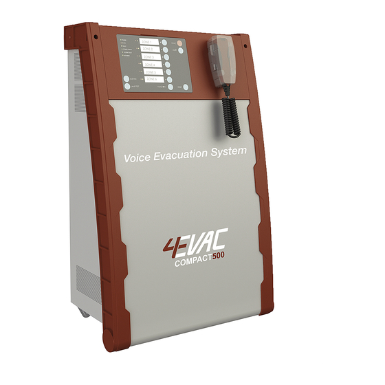
4EVAC Compact 500 quick guide
DoP OD 16.47
SUMMARY
This document is the quick guide for installation and initial setup of Compact 500 Voice Evacuation System.
It explains how the hardware of Compact 500 should be installed and configured. Quick guide is addressed
to the trained technical personnel, such as installers, service technicians and commissioning engineers.
Rev.
Date
REVISION AND APPROVAL
03
22-09-2017
04
25-03-2020
05
04-06-2020
Page 1 of 33
Nature of Changes
Corrected audio performance specs
General update
Corrections
Author:
Design revision:
Approved By
DD
AJH
TvdH
DD
2.0
Advertisement
Table of Contents

Related Manuals for 4EVAC Compact 500


Summary of Contents for 4EVAC Compact 500
- Page 1 DoP OD 16.47 SUMMARY This document is the quick guide for installation and initial setup of Compact 500 Voice Evacuation System. It explains how the hardware of Compact 500 should be installed and configured. Quick guide is addressed to the trained technical personnel, such as installers, service technicians and commissioning engineers.
-
Page 2: Table Of Contents
2. What else do I need to make it run? ..........................3 3. Where do I start? ..................................4 4. Unboxing 4EVAC Compact 500 ............................4 5. Mounting Compact 500 onto a wall ..........................5 6. Installation ....................................6 Open the cabinet ................................6 Mains .................................... -
Page 3: What's In The Box
Number of primary amplifier units (1, 2 or 3 units) Optional backup amplifier (0 or 1 unit) 2. What else do I need to make it run? 4EVAC Compact 500 needs additional items, which you are responsible to supply on your own. The additional equipment includes: Battery, Mains cord, Wall mounting plugs (5 pieces, ø8mm),... -
Page 4: Where Do I Start
DoP OD 16.47 3. Where do I start? First, make sure that you are officially allowed to access the Compact 500 hardware. This is usually the case you are an authorized representative of 4EVAC; you have been trained by 4EVAC or its authorized representative for installation, service and commissioning of the Compact 500 Voice Evacuation System. -
Page 5: Mounting Compact 500 Onto A Wall
At the back side of the Compact 500 cabinet you will find a wall-mount bracket provided with 3 fixing holes. Note the two slots in the back plate of the cabinet, corresponding to the wall bracket hooks. -
Page 6: Installation
Hacousto Holland bv Industrieweg 87 2651BC Berkel & Rodenrijs 4EVAC Compact 500 quick guide Author: Design revision: DoP OD 16.47 Caution! Never mount or un-mount the cabinet with battery inside! 6. Installation Caution! Risk of electric shock! Keep the mains switch OFF or unplugged from the mains outlet during the entire installation process. - Page 7 4EVAC Compact 500 quick guide Author: Design revision: DoP OD 16.47 After opening the Compact 500, you should see following functional sections, as shown on the picture below: Compact 500 – inside main unit Compact 500 - connection bay Page 7 of 33...
-
Page 8: Mains
NOTE: Place the battery only when the cabinet of Compact 500 is firmly fixed to the wall. Install only sealed lead-acid batteries for stationary use. Compact 500 is designed to operate with 2 x 12V batteries, each a maximum dimension of 230 x 138 x 207 mm (LxWxH). - Page 9 Caution! Be careful! The negative pole of the battery connector is directly connected to ground potential and the entire metal housing of Compact 500. Dropping an unprotected battery lead on any part of the hardware, housing or battery brings high risk of a short-circuit and may damage the hardware and the battery.
- Page 10 Hacousto Holland bv Industrieweg 87 2651BC Berkel & Rodenrijs 4EVAC Compact 500 quick guide Author: Design revision: DoP OD 16.47 Connect the battery leads in order FROM (+) TO (-), as follows: First, connect the (+) lead (long red) to the positive (+) pin of battery A;...
-
Page 11: Evac / Silence / Reset Inputs
Hacousto Holland bv Industrieweg 87 2651BC Berkel & Rodenrijs 4EVAC Compact 500 quick guide Author: Design revision: DoP OD 16.47 EVAC / SILENCE / RESET inputs There are 8 monitored inputs dedicated to triggering signals for evacuation, silence and reset instructions from the external fire detection system. -
Page 12: Evac Out
Also activated when the Compact 500 is not powered. 6.5.3. RESET out Activated (closed) immediately after a manual reboot of the Compact 500 main unit. The active pulse length is configurable from 0 (disabled) to 5000ms in the configuration settings. -
Page 13: Loudspeaker Lines
NOTE: Terminals BU1 and BU2 are not used. 6.7.1. Bridging to 200 W Each amplifier unit in Compact 500 offers 2 audio channels, max. 100W each. By default both channels are working independently, each with a 100V output. Loads greater than 100W (up to 200W) are handled by bridging outputs of both channels of the amplifier unit into one 200W channel. - Page 14 Hacousto Holland bv Industrieweg 87 2651BC Berkel & Rodenrijs 4EVAC Compact 500 quick guide Author: Design revision: DoP OD 16.47 6.7.1.1. Single channel For single channel mode (2x100W), two jumpers on the amplifier unit must be set to the “100V” position (center position).
- Page 15 Hacousto Holland bv Industrieweg 87 2651BC Berkel & Rodenrijs 4EVAC Compact 500 quick guide Author: Design revision: DoP OD 16.47 6.7.1.2. Bridged For bridged mode (1x200W), four jumpers must be set to the “50V” position (left & right position). Two jumpers per channel.
-
Page 16: Eol Board
DoP OD 16.47 6.7.2. EOL board EOL boards are not supplied with the Compact 500 main unit and are available at 4EVAC as a separate product. 4EVAC Compact 500 supports surveillance of loudspeaker lines based on a 20 kHz impedance measurement. -
Page 17: Analog Audio Input (Bgm)
2 as an external audio input for background music. Network ports 4EVAC Compact 500 offers 5 ports (RJ-45) for network connections between distributed parts of the 4EVAC Voice Evacuation System: 2 x G-Net ports (global network) 3 x L-Net ports (local network) The 4EVAC network features a full duplex RS-422 data link and 24V DC power to remote devices. -
Page 18: Global Network (G-Net)
6.9.1. Global network (G-Net) G-Net works as a redundant ring between Compact 500 main units. It is dedicated to secure a reliable system bus, which keeps the global system intact in case of single link failure. - Page 19 24V DC power ON jumpers in the RIGH position (or no jumper): 24V DC power OFF NOTE: If you connect G-Net directly between Compact 500 main units, please leave the power jumpers in the OFF position. Page 19 of 33...
-
Page 20: Local Network (L-Net)
DoP OD 16.47 6.9.2. Local network (L-Net) L-Net works as a daisy-chain bus between the Compact 500 main unit and remote network devices, such as paging consoles. It is dedicated to provide a powered bus to peripheral devices. Every L-Net port is powered with 24V DC and power over L-Net is always enabled. -
Page 21: Memory Card
The memory card is under constant surveillance, as well as its content. When the memory card is removed, damaged or its contents are corrupted, the Compact 500 will report a system fault. During the system fault caused by a memory error, the Compact 500 enters SAFE STATE, where the system stops all functions and requires a reboot. -
Page 22: Device Id Setting
Device ID setting The compact 500 is equipped with a rotary switch which determines the Device ID (or device address) in the network. Make sure that the Device ID set on the rotary switch complies with the ID defined in the configuration settings for this device. -
Page 23: Startup And Commissioning
Hacousto Holland bv Industrieweg 87 2651BC Berkel & Rodenrijs 4EVAC Compact 500 quick guide Author: Design revision: DoP OD 16.47 7. Startup and commissioning Finally, all hardware is set up, all connections are made and system is ready to run. Time to power it up! - Page 24 After changing a battery setting you should reboot the charger board. Press the RESET button on the charger board Why is it important? The power supply equipment of the Compact 500 implements a very precise voltage- and current-controlled charger with additional temperature compensation. It also keeps the battery under constant surveillance, including measurement of internal battery resistance in the order of milliohms, with accuracy within 1 mΩ.
-
Page 25: Power Supply Equipment Indications
Hacousto Holland bv Industrieweg 87 2651BC Berkel & Rodenrijs 4EVAC Compact 500 quick guide Author: Design revision: DoP OD 16.47 Power supply equipment indications In the top-left area of the charger board you will wind 5 LED indicators, where you can observe the current status of the power supply, battery and charger. -
Page 26: Loudspeaker Line Impedance Calibration
NOTE: Before calibrating impedance, please check the health state of every line with an impedance meter: Check load: measure every loudspeaker line individually with an impedance meter and check if the load is as expected. During measurement, the lines should be disconnected from the Compact 500 output. - Page 27 Hacousto Holland bv Industrieweg 87 2651BC Berkel & Rodenrijs 4EVAC Compact 500 quick guide Author: Design revision: DoP OD 16.47 EOL is disconnected, EOL impedance setting is incorrect. In case of one or more lines not calibrating, follow the indications on the amplifier units (next chapter) to identify the faulty line.
-
Page 28: Amplifer Unit Indications
Hacousto Holland bv Industrieweg 87 2651BC Berkel & Rodenrijs 4EVAC Compact 500 quick guide Author: Design revision: DoP OD 16.47 Amplifier unit indications Each amplifier unit has LED indicators onboard. There are 2 indicators per channel: GREEN LED: amplifier power-on/fault status;... - Page 29 Hacousto Holland bv Industrieweg 87 2651BC Berkel & Rodenrijs 4EVAC Compact 500 quick guide Author: Design revision: DoP OD 16.47 Every amplifier channel corresponds to the loudspeaker line as follows: 0 1 2 3 Amplifier slots AMP 1 AMP 2...
-
Page 30: Connections And Recommended Cable Types
Hacousto Holland bv Industrieweg 87 2651BC Berkel & Rodenrijs 4EVAC Compact 500 quick guide Author: Design revision: DoP OD 16.47 8. Connections and recommended cable types Connector Signal type Additional Recommended cable Max. length many type information (minimum) Analog audio in... -
Page 31: Technical Specifications
Hacousto Holland bv Industrieweg 87 2651BC Berkel & Rodenrijs 4EVAC Compact 500 quick guide Author: Design revision: DoP OD 16.47 9. Technical specifications Standalone system Number of zones max. 6 local zones Maximum total loudspeaker load 600 W RMS (420W RMS pure sinewave according to EN54-16) - Page 32 2500 m All information provided in this document is subject to change without notice. 4EVAC may also make improvements and/or changes in the products described in this information at any time without notice. Page 32 of 33...
- Page 33 Hacousto Holland bv Industrieweg 87 2651BC Berkel & Rodenrijs 4EVAC Compact 500 quick guide Author: Design revision: DoP OD 16.47 M A D E T H E N E T H E R L A N D S 4EVAC is a trade name of:...
Need help?
Do you have a question about the Compact 500 and is the answer not in the manual?
Questions and answers