Table of Contents
Advertisement
Quick Links
KNX PY
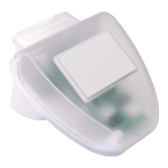
Pyranometer
Technical specifications and installation instructions
Item number 70157
EN
Elsner Elektronik GmbH Control and Automation Engineering
Sohlengrund 16
D - 75395 Ostelsheim Phone +49 (0) 70 33 / 30 945-0 info@elsner-elektronik.de
Germany
Fax
+49 (0) 70 33 / 30 945-20 www.elsner-elektronik.de
Advertisement
Table of Contents

Subscribe to Our Youtube Channel
Summary of Contents for Elsner KNX PY
- Page 1 Pyranometer Technical specifications and installation instructions Item number 70157 Elsner Elektronik GmbH Control and Automation Engineering Sohlengrund 16 D - 75395 Ostelsheim Phone +49 (0) 70 33 / 30 945-0 info@elsner-elektronik.de Germany +49 (0) 70 33 / 30 945-20 www.elsner-elektronik.de...
-
Page 2: Scope Of Delivery
(kilowatt hours per squaremetre). Both values can be read out by the KNX PY. Four switching outputs with adjustable threshold values as well as additional AND and OR logic gates are available.The sensor system, the evaluation electronics and the electronics of the bus... -
Page 3: Installation And Commissioning
Elsner Elektronik is not liable for any changes in norms and standards which may occur after publication of these operating instructions. - Page 4 Fig. 2 The sensor must be mounted onto a vertical wall (or pole). Wall pole Fig. 3 The sensor must be mounted horizontally in horizontal the lateral direction. Pyranometer KNX PY • Status: 08.03.2016 • Technical changes reserved. Errors reserved.
-
Page 5: Mounting The Sensor
Fig. 5 When wall mounting: flat side on wall, crescent- Collar shaped collar upward. Fig. 6 When pole mounting: curved side on pole, collar downward. Collar Pyranometer KNX PY • Status: 08.03.2016 • Technical changes reserved. Errors reserved. - Page 6 2.3.2. View of rear side and drill hole plan Fig. 10 a+b Drill hole plan Dimensions of rear side of housing with bracket. Sub- ject to change for technical enhancement. Langloch 7,5 x 5 mm Pyranometer KNX PY • Status: 08.03.2016 • Technical changes reserved. Errors reserved.
- Page 7 The sensor cover snaps in on the left and right along the bottom edge (see Fig.). Remove the cover. Push the connection cable through the rubber seal on the bottom of the device and connect voltage and data cable to the provided clamps. Pyranometer KNX PY • Status: 08.03.2016 • Technical changes reserved. Errors reserved.
- Page 8 “click”. Fig. 13 Make sure the cover and bottom part are properly snapped together! This picture is looking at the closed sensor from under- neath. Fastening Pyranometer KNX PY • Status: 08.03.2016 • Technical changes reserved. Errors reserved.
-
Page 9: Notes On Mounting And Commissioning
ATTENTION The device can be damaged if water penetrates the housing. • Do not clean with high pressure cleaners or steam jets. Pyranometer KNX PY • Status: 08.03.2016 • Technical changes reserved. Errors reserved.


Need help?
Do you have a question about the KNX PY and is the answer not in the manual?
Questions and answers