
Related Manuals for Tork Smart Switch Box


Summary of Contents for Tork Smart Switch Box
- Page 1 & automation SMART SWITCH BOX USER’S MANUAL PLEASE READ THE INSTRUCTİONS BEFORE USE JANUARY 2019 www.smstork.com...
-
Page 2: Table Of Contents
Factory Settings ..................................16 4. SSB INSTALLATION ..............................17 a. Mounting of SSB to Actuator ..........................17 b. Electrical Connection ..............................18 7. SSB SPARE PARTS ..............................18 8. PRODUCT TRANSPORTATION ..........................19 9. WARRANTY CONDITIONS ...........................19 SMS-TORK Endüstriyel Otomasyon Ürünleri San. Tic. Ltd. Şti. -
Page 3: Ssb General Details
When you want to control your actuator, either the opening or the closing coils remain in continuous energy. It causes energy consumption. The smart switch box cuts off the power of the coil after switching on or off while controlling the acutator. But as the command arrives, it ensures that the actuator remains open or closed. -
Page 4: Product Code
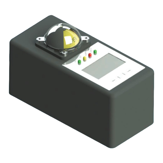
& automation c. Product Code The product code of the smart switch box is designated as SSB100. d . Exploded Picture Status Indicator Lexan Top Cover Electronic Screen Control Board Switch Cam Pressure Transmitters Proximity Switches Power Board Namur Valve... -
Page 5: Technical Details
• Mechanical switch is used as standard for output. Proximity switch can also be used on request. f. Switch Details In order to get position in the smart switch box, proximity sensors are used and mechanical switches are used for output. The switch brand, model and features used are as follows;... -
Page 6: Ssb's Working
After the entry, all devices belonging to the company will be displayed on the map and in the list. This screen also contains warning information for all devices. The switch box of the valve to be controlled from the list is selected by double-clicking. SMS-TORK Endüstriyel Otomasyon Ürünleri San. Tic. Ltd. Şti. - Page 7 valve & automation Figure 3: Device List Screen All information and warnings of the device and special settings for the device are displayed on the control screen. By clicking on the buttons, opening, closing and status monitoring is done. The following information is displayed on the control screen. Figure 4: Device ID number and valve position and command display screen www.smstork.com...
- Page 8 Figure 8: Valve opening and closing time display Figure 9: Warning screen All warnings and faults that occur in the actuator are included in the warnings area. Faults continue to remain as long as they continue. SMS-TORK Endüstriyel Otomasyon Ürünleri San. Tic. Ltd. Şti.
-
Page 9: Manual Control With Buttons
Manual Control with Buttons It is controlled manually with 4 buttons on the Smart Switch Box and necessary settings can be made. Also, status information is given with LEDs on the top of the screen visually. The control method is described in detail in Chapter 3.. -
Page 10: Ssb's Menu And Functions
Press MENU, UP, DOWN and OK arrow keys to switch between menus. a. Opening The TORK logo is opened when the SSB is energized. For the first used language selection is queried. Switches directly to the monitoring screen if it is not first use. -
Page 11: Monitoring Screen
valve & automation Figure 15: LANGUAGE tab Figure 16: Language selection screen c. Monitoring Screen The monitor screen is continuously active. If no button is pressed for 5 seconds in any menu, the screen is switched to this. From this screen, you can switch to the main menu screen and operate on other menus. -
Page 12: Settings
The opening and closing time measurements are made to determine whether the actuator is squeezed or strained. In case of passing all tests, the test successful letter will remain on the screen for 3 sec and switched to the monitoring screen. SMS-TORK Endüstriyel Otomasyon Ürünleri San. Tic. Ltd. Şti. -
Page 13: Counter Reset
valve & automation Figure 21: PST test result screen If the test fails at any step, the Test Fail message and the remaining test remain on the screen for 3 seconds and switched to monitoring screen. In addition, fault information will be on the Alerts screen and the ALARM led displays a red warning. Figure 22: PST test result screen f. -
Page 14: Manual Control
The purpose of this is to prevent the danger by any external intervention during maintenance. Manual control tab must be selected from the Settings screen to switch to manual control. Figure 28: Manual control setting screen SMS-TORK Endüstriyel Otomasyon Ürünleri San. Tic. Ltd. Şti. -
Page 15: Temperature Settings
valve & automation In order to switch to manual control, it is necessary to enter with the operator password for safety reasons. When the correct password is entered, manual control is started and on/off would be possible. Figure 29: Manual control password entrance screen After entering the correct password, the control screen will open. -
Page 16: Factory Settings
Factory Settings When return to factory settings, all settings other than Counter 1 are assigned the initial value. Password must be entered correctly to return to factory settings. Figure 33: Factory settings screen SMS-TORK Endüstriyel Otomasyon Ürünleri San. Tic. Ltd. Şti. -
Page 17: Ssb Installation
valve & automation 4. SSB INSTALLATION a. Mounting of SSB to Actuator Check the position of the actuator shaft and the position indicator before installing the switch box on the actuator. Mount the switch box to actuator with its bracket and screws. Figure 34: Mounting of SSB to actuator www.smstork.com... -
Page 18: Electrical Connection
Figure 35: SSB electrical connection schema 7. SSB SPARE PARTS SSB’s spare parts; • Electronic Control Cards • Position Indicators • Antenna • Air gland SMS-TORK Endüstriyel Otomasyon Ürünleri San. Tic. Ltd. Şti. -
Page 19: Product Transportation
8. PRODUCT TRANSPORTATION During transportation, ensure that the smart switch box does not fall to the ground and is not exposed to strong impacts. Do not put much weight on the smart switch boxes. Smart switch boxes must be carried in original carton boxes. - Page 20 SECTOR LEADER WITH 30 YEARS EXPERIENCE SMS-TORK Endüstriyel Otomasyon Ürünleri San. Tic. Ltd. Şti.
- Page 21 www.smstork.com...
- Page 22 F +90 216 364 37 57 HEAD OFFICE İMES O.S.B.S Cad. No:5 Çerkesl - D lovası KOCAELİ - TURKEY P +90 262 290 20 20 F +90 262 290 20 21 FACTORY SMS-TORK Endüstriyel Otomasyon Ürünleri San. Tic. Ltd. Şti /SMSTORK /sms-tork www.smstork.com...
Need help?
Do you have a question about the Smart Switch Box and is the answer not in the manual?
Questions and answers