Table of Contents

Related Manuals for Wahlberg 320.704


Summary of Contents for Wahlberg 320.704
-
Page 1: Safety Information
Remote Controlled Platform Series Item No. 320.704 (Off-Road), No. 320.703 (Standard) and No. 320.702 (Low Height) User Manual WWW.WAHLBERG.DK JENS JUULS VEJ 1 TELEPHONE: +45 86 18 14 20 8260 VIBY EMAIL: sales@wahlberg.dk DENMARK... - Page 2 If you have questions about how to operate the product safely, please contact you Wahlberg Motion Design supplier or Wahlberg Motion Design. Use only genuine Wahlberg Motion Design parts or parts approved by Wahlberg Motion Design.
-
Page 3: Table Of Contents
SAFETY INFORMATION INDEX TECHNICAL SPECIFICATIONS DRAWING INTRODUCTION ............................6 ACKAGE CONTENT ............................... 6 ESCRIPTION ............................... 7 REA OF USE ..........................7 SING FOR THE FIRST TIME ..............................7 RANSPORT PHYSICAL INSTALLATION ..........8 ASTENING THE MOTOR BRACKET BATTERY PACK AND CASTOR WHEEL TO AN OBJECT AC POWER .............................. -
Page 4: Technical Specifications
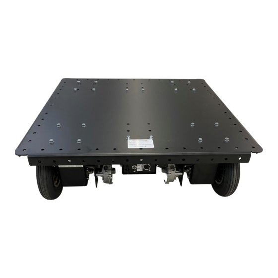
Charger for remote: 100-240 V AC 50-60 Hz Flash 8 only Charging time: 24 hours, optional rapid charger 1.5 hour Off-Road platform (320.704) Height: 240mm (9.5 in) Moving speed (No load): 2.0 m/s or 7.2 km/t (6.5 ft/s or 4.4 mph) Maximum Load: 200 kg (440.9 lb) -
Page 5: Drawing
Remote Controlled Platform Series (320) Item No. 320.704 (Off-Road) Item No. 320.703 (Standard) Item No. 320.702 (Low Height) 320.805.004 Date: 2022-02-09... -
Page 6: Introduction
Thank you for selecting the remote-controlled platform, a wireless controlled motor system from Wahlberg Motion Design. Before using the Wahlberg Motion Design product for the first time, please read this manual carefully. Failure in handling can cause injury of persons and/or damage the motors. -
Page 7: Area Of Use
Any other use of the product may result in a risk of injury of persons or equipment damage. Exceeding the load rating may cause failure of the equipment. Do not modify the product. For any modification of your product, contact Wahlberg Motion Design. -
Page 8: Physical Installation
WARNING! Make sure each motor bracket, battery pack and castor wheel are secured with minimum four bolts or screws to a stable platform. WARNING! Make sure both drive wheels and castor wheels can move freely in any direction. Fastening the motor bracket, battery pack and castor wheel to an object The standard product comes with each component securely mounted on a rectangular platform, but in some situations, you may desire to fasten each part from the existing platform directly to an object. - Page 9 The standard motor cabling is approx. 80cm (31 in) the following connections will apply. Wire Device Blue wire (- on forward) to upper tap (4.8mm) Left motor (turning right on forward) 404.386 (off-road and standard motor) Orange wire (+ on forward) to lower tap (6.3mm) Green wire (+ on forward) to lower tap (6.3mm) Right motor (turning left on forward) Brown wire (- on forward) to upper tap (4.8mm)
-
Page 10: Ac Power
WARNING 2 before connecting AC mains power to the charger. Voltage WARNING! Check that the voltage range specified on the charger matches the local AC mains power voltage before applying power to the charger. Power plug The charger unit comes with four changeable power plugs and contact your local electrician for another converter if needed. -
Page 11: Setup
2 before installing, powering, operating, or servicing the product. WARNING! Only experienced users should operate the product. Contact Wahlberg Motion Design for further information and education on motion equipment. WARNING! Make sure the object is secured on the platform and that the weight is within the limit, centered and does not make the platform unstable during acceleration and deacceleration. -
Page 12: Using The Remote
Using the remote WARNING! Make sure the Right Gimbal J1/J2 is in the centre position before turning ON the platform. For using the remote RadioLink AT9S Pro see page 16. The remote and the platform has been paired together at the manufacturing facility and the product is ready for use. -
Page 13: Speed, Ramp And System Settings (Factory Defaults)
Speed, ramp and system settings (Factory defaults) The following settings has been programmed into the remote by Wahlberg Motion Design, so this guideline is for customized setup and reprogramming in case settings are lost or critical parts are replaced. -
Page 14: Adjusting The Trims
Enter the [System.List] by press and hold the [Back] button while pushing the [Jog Dial] button. Sub menu Parameter Setting Note Management BACKLIGHT Always Off For maximum battery life set the backlight off and turn it on in low light situations. UI FEEDBACK To avoid the beep sound, like in theatres or similar locations. -
Page 15: Connecting The Platform
Connecting the platform Enter the [System.List] by press and hold the [Back] button while pushing the [Jog Dial] button. Sub menu Parameter Setting Note Spectra RECEIVER Opti&Mini System setting. When the above setting is selected, scroll down to the [BINDING] and press enter using the [Jog Dial] and the display will show. - Page 16 Using the remote AT9S Pro The AT9S Pro is a different remote control. It is not compatible with the Optima receivers and therefore the original remote control type should be used. Although the remote looks advance the platform will run out of the box simply my moving the right joystick. All other controls are for adjustment purposes.
-
Page 17: Fail-Safe Setting
Fail-safe setting WARNING: The Fail-safe must be activated and set correctly for safe operation! When the trim has been adjusted so there is no movement when the right gimbal is in the centre position, the fail-safe can be set by pressing the Link button [A] for about 6 seconds until the red LED[C] goes off, see Figure 5. -
Page 18: Service And Maintenance
ATTENTION! Signs of malfunction or poor operation should always lead to an inspection of the product. Spare parts Only parts ordered at or approved by Wahlberg Motion Design should be used in the product to ensure correct function and stability. Contact Wahlberg Motion Design to inquire about spare parts. -
Page 19: Platform Batteries
Platform batteries Internal Lead-acid batteries on the platform are maintenance free, and the product can be stored in any orientation, contact Wahlberg Motion Design for suitable replacement batteries and for further information on when and how to replace the batteries. -
Page 20: Appendix 3 - Block Diagram
Input/output 2.4GHz Band Power out Power in Power in 100-240V~ Charging Charging XLR 4 Pole Multiplug XLR 4 Pole Battery 2x12VDC Battery Remote controller Receiver 12AH charger Fused 12VDC 2xT16A (External) Power switch Motor controller +24V Left Right Drive wheel Drive wheel Gear Gear...
Need help?
Do you have a question about the 320.704 and is the answer not in the manual?
Questions and answers