APsystems ECU-C Installation And User Manual
Energy communication unit
Hide thumbs
Also See for ECU-C:
- Installation & user manual (39 pages) ,
- Quick installation manual (35 pages) ,
- Quick start manual (8 pages)

Related Manuals for APsystems ECU-C


Summary of Contents for APsystems ECU-C
- Page 1 Installation / User Manual APsystems ECU-C Energy communication unit with advanced functions Please scan this QR code © All Rights Reserved to download our APPs or click the link below: http://q-r.to/1OrC...
-
Page 2: Table Of Contents
5.15 ECU AP Settings ........................29 5.16 Do-It-Yourself(DIY) Registration ..................30 5.17 Settings ............................31 6.Local Network Interface ........................32 6.1 Connecting to the ECU-C via the Local Wireless ............. 32 6.2 Home Screen ..........................32 6.3 Real-time Data Screen ......................34 6.4 Administration Screen ......................34 6.5 Advanced Screen ........................ -
Page 3: Important Safety Instructions
The inverter and endues system may only be commissioned and operated by qualified personnel. This equipment is not suitable for use in locations where children are likely to be present. ECU-C Installation/User Manual... -
Page 4: Introduction
Internet database in real time. Through the APsystems Energy Monitoring and Analysis software, the ECU-C gives you precise analysis of each microinverter and module in your solar installation from any web-connected device. The ECU-C’s integrated http web server offers the simplest and most flexible network integration of any data logger on the market. -
Page 5: Interface Explanation
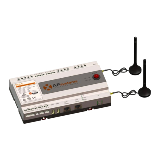
2.Interface Explanation Interface Layout The ECU-C interface includes, (figure 2)from left to right, are Reset、Relay Feedback Input、Relay Output、Grid CT、Production CT、AC Input. (figure 3)from left to right, are Port、DC、RS232、RS485、USB1、USB2、 RJ45、Internet、RJ45 Signal、AP. (figure 4)from left to right, are antenna(Zigbee)、antenna(Wifi). Reset Relay Feedback Input Relay Output Grid CT Production CT AC Input... -
Page 6: Ac Input Port
The DC Input port connects power through the 16V DC power line. 2.3 RJ45 Ethernet Network Port The ECU-C allows the user to communicate with the EMA, or log in to the ECU-C's local page in the absence of the wired LAN and WLAN, to set up the system and view the system data via Ethernet network port. -
Page 7: Power
(Zigbee signal), the other antenna is used for the Wi-Fi connection between ECU-C and router. 2.9 LED The OK light will blink when ECU-C starts up, and it will keep on after registering. The Comm light will be on when the ECU-C connects to EMA. -
Page 8: Hardware Installation
Choose a location that is electrically as close to the array as possible. The ECU-C is NOT rated for outdoor use, so if installing outdoors near a junction box or breaker panel, make sure you enclose it in an appropriate weatherproof NEMA electrical box. - Page 9 If the roof is metal, please use this long cable antenna, and place it outside or on roof. 2) Using a Wall Mount When mounting the ECU-C to a wall, make sure to select a cool, dry indoor location. ...
-
Page 10: Cable Connections
3.4 RJ45 Signal connection Plug the RJ45 connector in the package to RJ45 Signal port. 3.5 Internet Connection There are three different approaches to connecting the ECU-C to the Internet: Option 1: Direct LAN cable connection. Make sure the LAN cable is connected to the network port on the bottom of the ECU-C. - Page 11 4G SIM Figure 11 Option 2: Wireless Connection. Use ECU-C internal WLAN (see Managing the WLAN Connection, pg. 23). Option 3: Using a PLC bridge: Make sure the LAN cable is connected to the network port on the bottom of the ECU-C.
- Page 12 3.Hardware Installation The network cable in the package can be used to connect the ECU-C with PC directly. One side is connected with the ECU-C and the other side is connected with the PC. Then change the IP address and the network mask to 192.168.131.1 and 255.255.255.0, respectively.
-
Page 13: Current Transformer Interface
3. The wiring of the CTs: White wires connect to “+” Production CT ports on ECU-C and black wires connect to “-” Grid CT ports on ECU-C. 4. CTs are as optional accessories provided, to ensure the CTs could match... -
Page 14: Contactor Connection
3.Hardware Installation Please ensure that the ECU-C is in a power off state when installing the transformer.APsystems can provide the current transformers, please contact us or our distributors. 3.7 Contactor connection ECU-C provides two contact driver signal interface, two-way contact signal interface. -
Page 15: Basic Operation
The following diagram shows the connetions on the bottom of APsystems the ECU-C. RESET Figure 15 To restore the ECU-C’s factory settings, simply press the “Reset” button for three seconds or longer. The unit will automatically return to its default settings. ECU-C Installation/User Manual... -
Page 16: Ema Manager
Professional installers: all features available DIY (Do It Yourself) installers: only ECU_APP features available EMA APP: for end-users only 5.1 Connecting to the ECU-C via the Local Wireless Open Wi-Fi setting in your smartphone, default no password. Open theEMA Manager. -
Page 17: Add Uid
5.EMA Manager 5.2 Add UID Enter microinverters UID (serial numbers) into the ECU-C Click “Workspace”, select “ID Management”, input microinverters UID (serial number: 12 digits starting with a 4, a 5, a 7 or a 8) manually or scan the UID with your smartphone or tablet scanner. -
Page 18: Delete Uid
Note: when deleting, please press also “Sync”. Otherwise the microinverter will not be removed from the ECU-C. Once the microinverters UID have been successfully entered into the ECU-C, you need to select grid profile and define the adequate time zone of your ECU. 5.5 Grid Profile ... -
Page 19: Time Management
5.7 Meter Settings After the metering functions activated and CTs (current transformers) in place, the meter data will be displayed, and different control functions can be selected. ECU-C Installation/User Manual... - Page 20 Conversely, if the Power Limit is set to 0 and the site is using 3kW and the array can produce 8kW the inverters will curtail power production to meet the demand. In addition, the ECU-C is designed to dynamically adjust to the changing demand of the site automatically in real-time to realize the full potential of the array.
- Page 21 Select the ‘Redundant Energy Control’ under ‘Parameter settings’ This function is to control the opening of the external AC contactor by closing the ECU-C relay when the power of the uploaded power grid reaches a certain power value, to supply power to external electrical equipment e.g., water heater, pool pump, air conditioner, etc.
-
Page 22: Modbus Settings
5.EMA Manager 5.7.3 Three-phase Balance When using APsystems single-phase micro-inverse to form a three-phase system, the three-phase balance function can be turned on to ensure that the three-phase current difference does not exceed 16A. The three-phase balance function can be connected to the detection current through an external CT, and the response speed is faster;... - Page 23 The host’s RS485 port must be configured to the same baud rate, 8 data bits, 1 stop bit, none parity bit. Not compatible with split-phase (2 phases) systems as commonly used in the Americas. 5.EMA Manager ECU-C Installation/User Manual...
-
Page 24: Ecu Network Settings
The first bullet (with ECU UID) is green when the smartphone/tablet is properly connected to the ECU hotspot. The 2nd bullet shall be green if the internet connection to the router has been successfully established. ECU-C Installation/User Manual... - Page 25 ECU’s wired network setting has 2 options: automatically obtain an IP address: the router will give an IP address to the ECU-C automatically (preferred method) . use a fixed IP address. In that case, you need to enter enter IP address, subnet mask, default gateway, Preferred DNS server and Alternate DNS server.
-
Page 26: Checking The Commissioning Of The Ecu-C
The 2nd bullet shall be green if the internet connection to the router has been successfully established. 5.10 Checking the commissioning of the ECU-C Once the ECU-C has been commissioned, installer can check status on the home page of the ECU APP: Several infos are displayed... -
Page 27: Module
On the module page, installer can visualize the performance of microinverters registered into the ECU. Click “Panel”: the detailed information of the microinverter is displayed, including inverter UID, PV module DC power, grid voltage, frequency and temperature. ECU-C Installation/User Manual... -
Page 28: Data
In this page, you can view the detailed data on ECU level: -Per day -Per month If with metering functions activated and CTs (current transformers) in place, you can also visualize PV production, house-hold consumption and grid import/export data on meter level. ECU-C Installation/User Manual... -
Page 29: Inverter Connection Progress
ECU, 100% means the connection is over. The microinverters with "OK" are properly connected to the ECU ECU-C User Interface 5.14 Automatic System Check Once the ECU has been commissioned, the menu “Automatic System Check” can help you to check proper communication and production of each microinveter. -
Page 30: Ecu Ap Settings
5.15 ECU AP Settings This menu can be used if you would like to change the default password of the ECU-C hotspot. Please connect to the ECU hostpot first, open the menu “ECU APP settings” and change the password at your convenience. -
Page 31: Do-It-Yourself(Diy) Registration
EMA APP. Once the ECU has been properly commissioned, make sure to connect your smartphone or tablet to local internet. Enter “Do it Yourself Registration Menu” and follow instructions to create your own EMA account. ECU-C Installation/User Manual... -
Page 32: Settings
5.EMA Manager 5.17 Settings This basic menu allows you to change the Language: English, French, Spanish, Portuguese, Polish, Simplified Chinese and traditional Chinese. We're adapting to more languages. ECU-C Installation/User Manual... -
Page 33: Local Network Interface
Turn on the Wi-Fi function on PC or phone. Scan the ECU ’s SSID which named “ECU-WIFI_XXXX” (the “xxxx” refers to the last 4 numbers of the ECU-C ID), connect to the ECU-C’s SSID. The first connection has no password. - Page 34 Amount of power that has been generated during the most current day. Last connection to Website: The last time the ECU-C checked into the central APsystems EMA database. Number of Inverters: Number of inverters that have programmed into the ECU-C.
-
Page 35: Real-Time Data Screen
Figure 19 a) Real Time Data To view the real-time system operation data statistics for your solar array, click “Real Time Data” from the ECU-C home screen to navigate to the real-time data screen. b) Trend of system power To view the system power of any period, click "Power" at the real-time data page. - Page 36 6.Local Network Interface a) Managing Inverter IDs The inverter IDs must be programmed into the ECU-C for the ECU-C to recognize the inverters. The ECU-C will NOT auto-sense the inverters. Initial Programming of the ECU-C with the Inverter IDs. The “Enter Inverter ID” window field will be blank if you have not yet entered any of the inverter IDs.
- Page 37 The ECU-C can both work in two modes: WLAN and Local Wireless Access. In WLAN mode, the ECU-C can connect to a router by Wi-Fi. In Local Wireless Access mode, user’s phone or PC can connect to ECU-C to access local web.
-
Page 38: Advanced Screen
2) On the page, you can modify SSID, Channel, Safe Type and Password. If you don’t select the Safe Type, the Password is hidden. g) Firmware Update Select the ECU-C upgrade package, and click OK to upgrade ECU-C firmware. The upgrade package can be downloaded at www.APsystems.com. - Page 39 After turning on the Zero Export function, if the power limit value is not filled, the default is 0, that is, when the ECU-C detects that the power generated by the photovoltaic system is uploaded to the grid (reverse...
-
Page 40: Remote Ecu-C Management (Ema)
APsystems Energy Monitoring & Analysis (EMA) website, using your installer login credentials. Changes made remotely through the EMA do not take effect until the ECU-C’s next reporting cycle. The ECU-C must first be installed with Internet connectivity. -
Page 41: Ecu-C Configuration/Ecu-C Status Page
Set Time Zones The ECU-C time zone can be set or adjusted remotely through the ECU-C setting tab. If the time zone is not properly set, the solar production data will not post properly on the EMA site. Load Inverter IDs ... -
Page 42: Setting The Ecu-C Time Zone
7.Remote ECU-C Management (EMA) 7.2 Setting the ECU-C Time Zone 1) Click the remote control menu to enter the remote settings page 2) Select the “ECU-C SETTING” tab. The ECU-C Configuration page is displayed. Time Zone Pull Down Field Figure 25 Using the “Time Zone”... - Page 43 7.Remote ECU-C Management (EMA) Operation Selection (Add or Delete) Inverter ID Field Figure 27 Adding Complete List of Inverter IDs for a Newly Installed System There are two different approaches to add the inverter IDs: Option 1: Webpage - 1. Select Add inverter based on registration list 1) Select “Add”...
- Page 44 The correct disposal of your old appliance will help prevent potential negative consequences for the environment and human health. For more detailed information about disposal of your old appliance, please contact your city office, waste disposal service or the shop where you purchased the product. ECU-C Installation/User Manual...
- Page 45 Tel: 61 (0)2-8034-6587 Mail: info.apac@APsystems.com APsystems Europe Karspeldreef 8, 1101 CJ, Amsterdam, The Netherlands Tel: +31 (0)85 3018499 Mail: info.emea@APsystems.com APsystems EMEA C/Bulnea 244c rue du Point du Jour 01000 Saint Denis lès Bourg Tel: +33-481-65-60-40 Mail: info.emea@APsystems.com ECU-C Installation/User Manual...
Need help?
Do you have a question about the ECU-C and is the answer not in the manual?
Questions and answers