Advertisement
SURGE PROTECTION
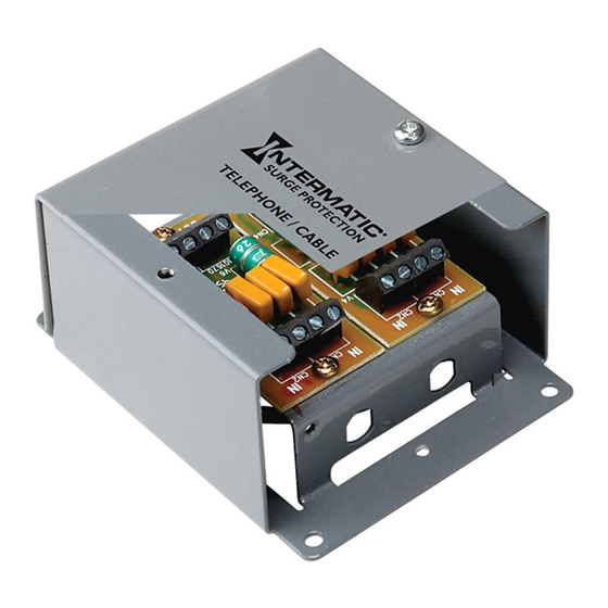
Coaxial Cable Indoor Stand Alone Protection
Models
Model Numbers:
IG1CM
Optional Modules
IG1C
Parts List
Description
Mounting Frame
Cover / Back Plate
IG1C (second module optional)
Screws-self threading (3/8" Torx T20 / slot head)
Ground Wire
3/4" x 6 Pan Head Screws (
3/4" anchors (
not shown
Additional Parts
Flush Mount Kit
Description
Flush Mount Cover Plate
Mounting Bracket
Screws-self threading (3/8" Torx T20 / slot head)
Screws-self threading (5/8" Torx T20 / slot head)
3/4" x 6 Pan Head Screws
Tools Required
Flat head screw driver, Torx head
screw driver, Awl or hole punch, drill,
1/8" and 3/16" bits.
Notes:
1. Coaxial protection is compatible with
Local antenna, Cable/Satellite and
Cable Internet lines.
2. Telephone protection is compatible
with Voice and Fax lines, Modem lines
and DSL (Digital Subscriber Lines.)
Before Installing
1.
Check the parts in both packages against the Parts Lists shown above. Contact Intermatic if parts are missing.
2.
It is suggested that you read these instructions completely before installing the Stand Alone Protection (SAP) unit.
Flush Installation
Description:
1-line coaxial cable protector with indoor enclosure (NEMA 1)
coaxial cable protection module
Quantity Reference
)
not shown
)
Quantity
J
I
NSTALLATION
1
A
1
B
1
C
2
D
1
E
4
4
B
D
Reference
1
F
1
G
4
H (Fig.4)
2
J
4
(
)
not shown
A
F
I
NSTRUCTIONS
C
C
Figure 1
G
E
Figure 2
E
A
E
D
B
Advertisement
Table of Contents

Subscribe to Our Youtube Channel
Related Manuals for Intermatic IG1CM


Summary of Contents for Intermatic IG1CM
- Page 1 DSL (Digital Subscriber Lines.) Before Installing Check the parts in both packages against the Parts Lists shown above. Contact Intermatic if parts are missing. It is suggested that you read these instructions completely before installing the Stand Alone Protection (SAP) unit.
- Page 2 availability should be a consideration when selecting an installation location. Do not install Protection Devices during Electrical Storms. COAXIAL LINE PROTECTION Remove the Cover (B) from the Stand Alone Protector (SAP) unit by removing the two Tory Head screws (D) and separating the Cover (B) from the Mounting Frame (A). Remove the IG1C coax module from the Mounting Frame by removing the outer hex nut from each of the F-thread connectors.
- Page 3 In the case of a Coax Protector failure, the signal to the equipment may be interrupted or degraded. The protector should be bypassed until a replacement unit is obtained and installed. For troubleshooting assistance, call Intermatic at (815) 675-7000 or (800) 391-4555 NOTE: The IG1C module is bi-directional.
- Page 4 INSTALLATION NOTES: This plate may be installed in the Vertical or Horizontal position. Position this template over the surface and mark the cut-out area through the template. Carefully cut out the marked area. NTERMATIC NCORPORATED Spring Grove, Illinois 60081 http://www.intermatic.com 158IG12079...
Need help?
Do you have a question about the IG1CM and is the answer not in the manual?
Questions and answers