Sign In
Upload
Download
Table of Contents
Contents
Add to my manuals
Delete from my manuals
Share
URL of this page:
HTML Link:
Bookmark this page
Add
Manual will be automatically added to "My Manuals"
Print this page
×
Bookmark added
×
Added to my manuals
Manuals
Brands
SHIMGE Manuals
Water Pump
SHF
Service manual
SHIMGE SHF Service Manual
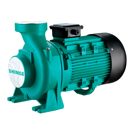
Mini-type clean-water centrifugal electric pump
Hide thumbs
1
Table Of Contents
2
3
4
5
6
7
8
9
10
11
12
13
14
15
16
17
18
19
20
page
of
20
Go
/
20
Contents
Table of Contents
Troubleshooting
Bookmarks
Advertisement
Table of Contents
1
Table of Contents
2
Safety Precautions
3
Product Introduction
4
Operating Conditions
5
Structure Diagram
6
Pump Wiring Diagram
7
Installation Diagram
8
Instructions for Installation
9
Maintenance
10
Troubleshooting
Download this manual
SERVICE MANUAL
Vortex Type Micro Clean Water Pump
Mini-type Clean-water Centrifugal Electric Pump
Models: SHF(m)、CP(m)、PRm、SGA(m)、PX(m)、PUM、
2SGP(m)、SGT、KSW、PC、CPH、ZDK
Table of
Contents
Previous
Page
Next
Page
1
2
3
4
5
Advertisement
Table of Contents
Need help?
Do you have a question about the SHF and is the answer not in the manual?
Ask a question
Questions and answers
Related Manuals for SHIMGE SHF
Water Pump SHIMGE SQm User Manual
(4 pages)
Water Pump SHIMGE SQm Service Manual
Vortex type micro clean water pump (23 pages)
Water Pump SHIMGE SGJW Series Service Manual
Mini-type clean-water electric jet pump (16 pages)
Water Pump SHIMGE SG(m) Series Service Manual
Mini-type clean-water centrifugal electric pump (17 pages)
Water Pump SHIMGE CPm Service Manual
Mini-type clean-water centrifugal electric pump (20 pages)
Water Pump SHIMGE PX Service Manual
Mini-type clean-water centrifugal electric pump (20 pages)
Water Pump SHIMGE WQ(D) Series Service Manual
Submersible electric sewage pumps (24 pages)
Water Pump SHIMGE JET Series Service Manual
Mini-type clean-water electric jet pump (16 pages)
Water Pump SHIMGE QX Series User Manual
Submersible pump (6 pages)
Water Pump SHIMGE QGYD Service Manual
Oil-filled submersible screw pump (12 pages)
Water Pump SHIMGE PW Service Manual
Vortex type micro clean water pump (23 pages)
Water Pump SHIMGE WQK Series Service Manual
Submersible electric sewage pumps (24 pages)
Water Pump SHIMGE WVSD Series Service Manual
Submersible electric sewage pumps (24 pages)
This manual is also suitable for:
Shfm
Cp
Cpm
Sga
Sgam
Px
...
Show all
Pxm
Pum
2sgp
2sgpm
Sgt
Ksw
Pc
Cph
Zdk
Table of Contents
Save PDF
Print
Rename the bookmark
Delete bookmark?
Delete from my manuals?
Login
Sign In
OR
Sign in with Facebook
Sign in with Google
Upload manual
Upload from disk
Upload from URL


Need help?
Do you have a question about the SHF and is the answer not in the manual?
Questions and answers