
Related Manuals for SHIMGE SG(m) Series


Summary of Contents for SHIMGE SG(m) Series
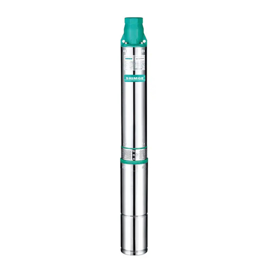
- Page 1 SERVICE MANUAL Mini-type Clean-water Centrifugal Electric Pump SG(m)、SE(m)、SS(m)、QJD Models:...
-
Page 2: Table Of Contents
Contents I. Product Introduction II. Operating Conditions III. Structure Diagram IV. Instructions for Installation and Use V. Maintenance VI. Troubleshooting... -
Page 3: Product Introduction
Thank you very much for choosing our products, and please read over the Operating Manual and keep it properly before the installation and use. • The Electric Pump must be grounded reliably before use, and shall be equipped with an electrical leakage protection device; •... -
Page 4: Structure Diagram
III. Structure diagram 38 Retaining ring 37 Valve cover 19 Middle bearing block 36 Discharge chamber 18 Middle rubber bearing 35 Adjusting washer 17 Ceramic shaft sleeve 34 Discharge chamber back ring 16 Guide vane 33 Oring 32 Screw 15 Wear washer 31 Spring washer 14 Fluid director 30 Locating pin... - Page 5 27 Sand prevention sleeve Thermal protector: all single phase, three phase of 0.75~3kW. 26 Hex nut Three phase of 4~7.5kW required external protection control box 25 Sand prevention cushion 24 Sand prevention seat 11 Stator core with winding 23 Full-thread bolt 22 Oring 21 Cable press plate 20 Cable plug...
- Page 6 27 Dust cover 15 Small press plate 14 Pump sleeve 26 Discharge chamber 13 Press plate for the flat cable 25 Adjusting shim 12 Cross recess oval head 24 Oring screw 11 Small press plate 23 Valve cover 10 Pump shaft 9 Wear washer 22 Upper block 8 Guide vane...
- Page 7 30 Outer plug 10 Deep groove ball 29 Spring washer bearing 28 Hexagon socket set screws with flat point 9 Stator core with 27 Cover plate winding 26 Sand prevention sleeve 25 Sand prevention cushion 24 Sand prevention seat 8 Insulation paper 23 Air Faucet 22 Oring 7 Bearing block...
- Page 8 38 Dust cover 18 Guide vane 37 Retaining ring 17 Guide vane collar 36 Valve cover 35 Screw 16 Impeller 34 Spring washer 15 Cover plate for the 33 Discharge chamber guide vane 14 Lower supporting block 32 Locating pin 13 Lower supporting block collar 31 Pump shaft gasket...
- Page 9 31 Outer-hexagonal flat screw 11 Stator core with winding 30 Plug 29 Sand throwing sleeve 28 Cross-recessed lentil- headed screw 27 Gland for the wear ring 26 Air faucet 10 Lower retaining sleeve 25 Wear ring 24 Framework oil seal 23 Spring washer 22 Screws set 21 Terminal...
- Page 10 1 Dust cover 2 Discharge chamber 3 Oring 11 Middle bearing block 4 Small press plate 12 Middle rubber bearing 13 Ceramic shaft sleeve 14 Guide vane 5 Cable press plate 6 Pump sleeve 15 Wear washer 7 O-shaped seal ring 8 Valve deck 9 Upper seat 16 Fluid director...
- Page 11 21 Deep groove ball bearing 1 Pump spindle shaft 22 Stator core with winding 2 Cross recessed countersunk head screw 3 1-type hex nut 4 Spring washer 5 Hexagon socket set screws with flat point 6 Threaded gland for the cable 23 Motor Bracket 7 Cable packing washer 8 Round-hole rubber jacket...
-
Page 12: Instructions For Installation And Use
IV. Instructions for Installation and Use Pressure gage Check valve Valve Drainage hole Well lid Slpint Cable Rope Lifting rope Water pipe Electric Pump Sandy soil at the well bottom Installation Diagram 1.Before installation and use, please fully check whether the Electric Pump is damaged during transportation or storage, for example, whether any cable or terminal box is in a perfect condition. - Page 13 ③ ② ① ≥60mm At least 10 times as the diameter of the conductor. 1.Remove the insulating layer 1.Divide each connector into 1.Clench each strand. First get one strand without damaging the several strands evenly (no less from the middle and make it wind to one conductor.
- Page 14 5.Before putting the Electric Pump into water, please carry out a test running for no more than 10 seconds and simultaneously check whether the rotational director of the pump shaft is the same as that indicated by the indicating arrow in the nameplate. 6.Connect a delivery pipe (whose specifications are selected based on Table 1) matching with the discharge chamber.
-
Page 15: Maintenance
11.Oil-filled electric pump filled with No. 10 white food machinery oil so as to ensure that the mechanical seal is effectively lubricated and cooled, which might leak in case of any damage or fault of the Electric Pump. The leaked white oil might damage the botany planted or the animal bred or pollute the drinking water or food involved in any application relating to planting, breeding, or delivery or processing of drinking water or food. -
Page 16: Troubleshooting
c) When the replacement of No. 10 white food machinery oil for an oil-filled motor, the motor must be fully filled. 3.If the Electric Pump is not used for a long time, it should not be submerged in water. Place it in clean water for energized operation for minutes, clear away the condensate inside and outside the Pump, dry it, and then carry out rust-proof treatment, and finally put it at a well- ventilated dry place. - Page 17 Fault Cause Remedy 1. The mechanical seal is damaged and Do troubleshooting, disassemble the water leakage happens, resulting winding and re-insert the winding as Stator interturn or interphase short circuit. per the concerned technical winding 2. The impeller is blocked. requirements as well as immerse and burnt 3.
Need help?
Do you have a question about the SG(m) Series and is the answer not in the manual?
Questions and answers