Advertisement
Quick Links
INSTRUCTION MANUAL
INSTALLATION BASE
BEFORE USE ....
Thank you for choosing M-System. Before use, please check
contents of the package you received as outlined below.
If you have any problems or questions with the product,
please contact M-System's Sales Office or representatives.
■ PACKAGE INCLUDES:
Base ............................................................................... (1)
■ MODEL NO.
Confirm Model No. marking on the product to be exactly
what you ordered.
■ INSTRUCTION MANUAL
This manual describes necessary points of caution when
you use this product, including installation, connection and
basic maintenance procedures.
POINTS OF CAUTION
■ CONFORMITY WITH EU DIRECTIVES
• The equipment must be mounted inside the instrument
panel of a metal enclosure.
• The actual installation environments such as panel con-
figurations, connected devices and connected wires may
affect the protection level of this unit when it is integrated
in a panel system. The user may have to review the CE
requirements in regard to the whole system and employ
additional protective measures to ensure CE conformity.
■ GENERAL PRECAUTIONS
• Before you remove the base or mount it, turn off the power
supply for safety.
■ ENVIRONMENT
• Indoor use
• When heavy dust or metal particles are present in the air,
install the unit inside proper housing with sufficient ven-
tilation.
• Do not install the unit where it is subjected to continuous
vibration. Do not subject the unit to physical impact.
• Environmental temperature must be within -10 to +55°C
(14 to 131°F) with relative humidity within 30 to 90% RH
in order to ensure adequate life span and operation.
■ WIRING
• Do not install cables close to noise sources (relay drive
cable, high frequency line, etc.).
• Do not bind these cables together with those in which
noises are present. Do not install them in the same duct.
(free I/O address)
5-2-55, Minamitsumori, Nishinari-ku, Osaka 557-0063 JAPAN
Phone: +81(6)6659-8201 Fax: +81(6)6659-8510 E-mail: info@m-system.co.jp
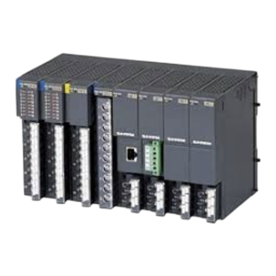
MODEL
FRONT VIEW
I/O 1
I/O 2
SW1
SW2
I/O MODULE ADDRESS
Free I/O module address can be assigned to each module po-
sition using the rotary switch, within 1 to 16. Every module
can be mounted on any position.
Switch positions and addresses correspond to each other as
shown below:
I/O module address
Rotary switch position
1
2
:
n
:
16
DO NOT assign one address to more than one I/O module to
ensure adequate operations and to prevent failures.
In case of power supply module, interface module, they op-
erate normally even address is conflicted.
For a power supply module, be sure to install in the right
end slot or left end slot for heat dissipation. In the case of
redundant power supply, consecutively install them in the
right end slot or left end slot.
Example for R3-BSW04
Power
Interface
Supply
Module
Module
I/O module address
4
Rotary switch position
3
R3-BSW
R3-BSW
I/O n
SWn–1
SWn
0
1
:
n – 1
:
F
I/O
I/O
Module
Module
3
1
2
2
0
1
EM-8357 Rev.7
P. 1 / 3
Advertisement

Related Manuals for M-system R3-BSW


Summary of Contents for M-system R3-BSW
- Page 1 R3-BSW MODEL (free I/O address) BEFORE USE ..FRONT VIEW Thank you for choosing M-System. Before use, please check I/O 1 I/O 2 I/O n contents of the package you received as outlined below. If you have any problems or questions with the product, please contact M-System’s Sales Office or representatives.
- Page 2 Panel bottom or wiring conduit (height ≤50 mm or 2 in.) ■ WALL MOUNTING unit: mm (inch) (1.18) (1.02) (1.18) n–M4* n = Number of slots × 2 EM-8357 Rev.7 P. 2 / 3 5-2-55, Minamitsumori, Nishinari-ku, Osaka 557-0063 JAPAN Phone: +81(6)6659-8201 Fax: +81(6)6659-8510 E-mail: info@m-system.co.jp...
- Page 3 MODEL R3-BSW04 112 (4.40) R3-BSW06 168 (6.61) R3-BSW08 224 (8.82) R3-BSW10 280 (11.02) R3-BSW12 336 (13.23) R3-BSW14 392 (15.43) R3-BSW16 448 (17.64) EM-8357 Rev.7 P. 3 / 3 5-2-55, Minamitsumori, Nishinari-ku, Osaka 557-0063 JAPAN Phone: +81(6)6659-8201 Fax: +81(6)6659-8510 E-mail: info@m-system.co.jp...
Need help?
Do you have a question about the R3-BSW and is the answer not in the manual?
Questions and answers