Advertisement
Quick Links
GUIDE TO INSTALLATION
AND MAINTENANCE
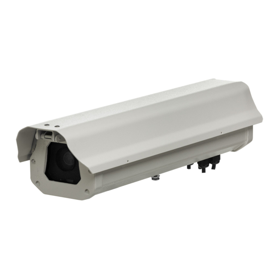
POSITIONING ITSCAM FF 600 AT VIA
1. Select an existing pole or gantry that allows positioning the ITSCAM FF
600 preferably centered on the track, with the objective of capturing images
of one or two lanes of the track, considering the linear distance between the
equipment and the image center:
Image Center
d
d
d
ITSCAM FF 600
D minimum
10 meters
D maximum
17 meters
When using an Illuminator in conjunction with ITSCAM
FF 600, check in the product specifications which
minimum and maximum distance must be observed in
relation to the position of the object to be illuminated.
CONNECTING TO ITSCAM FF 600
2. Pass the connection cables through the PG9 cable glands, considering
the preferred usage of each:
Illuminator 2
Power Cable
Illuminator 1
Ethernet Cable
3. Tighten the cable gland until the cable is completely fixed.
4. Go to the available interfaces on the Connections Board or on the back
panel of the ITSCAM 600 device to connect the cables:
Connections
Side positioning
Board
to the track
5. Use the connectors available on the back panel of the ITSCAM
600 device:
SD Card
4G/3G/2G Antenna
Wi-fi Antenna
The SD card must always be plugged in for the correct
functioning of ITSCAMPRO Móvel plugin .
6. Make the RS-485 and RS-232 data connections with the Connections
Board considering the connectors interfaces and their colors:
ITSCAM 600
back panel
USB 2.0
Ethernet 2GB
SIM Card
MOV Antenna
GPS Antenna
485_GND
485_B
P9
485_A
232_GND
P11
232_TX
232_RX
26/04/2022
Revision 1.0
1/4
Advertisement

Related Manuals for PUMATRONIX ITSCAM FF600


Summary of Contents for PUMATRONIX ITSCAM FF600
- Page 1 POSITIONING ITSCAM FF 600 AT VIA 4. Go to the available interfaces on the Connections Board or on the back panel of the ITSCAM 600 device to connect the cables: 1. Select an existing pole or gantry that allows positioning the ITSCAM FF ITSCAM 600 600 preferably centered on the track, with the objective of capturing images back panel...
- Page 2 7. Perform power connections to the Connections Board, considering the 10. Go to the menu Equipment > Network on the Ethernet tab. WI- FI NETWORK CONFIGURATION (IoT P4 connector interfaces and their respective colors: DEVICES) 11. Enter a network ID in the Hostname field. The Wi-Fi, 4G and 3G network interfaces are disabled in the equipment's factory default settings.
- Page 3 3G OR 4G MOBILE NETWORK SETUP 36. Avoid blocking out parts of the image by objects such as trees or 41. Check at the home screen the available zoom and focus controls in the vehicles from other tracks. Live feed window (of adjustable size), in the scroll bars on the left. If it is not enabled, select from the window's settings: The Wi-Fi, 4G and 3G network interfaces are disabled in the equipment's factory default settings.
- Page 4 Power cable The replacement of defective parts and the execution of services resulting from this warranty will only be carried out at the Pumatronix 47. Connect the wires of the 2 ITSLUX cables following the colors and Authorized Technical Assistance or a third party expressly indicated by connectors indicated on the Connections Board: it, where the product must be delivered for repair.
Need help?
Do you have a question about the ITSCAM FF600 and is the answer not in the manual?
Questions and answers