Table of Contents
Advertisement
Quick Links
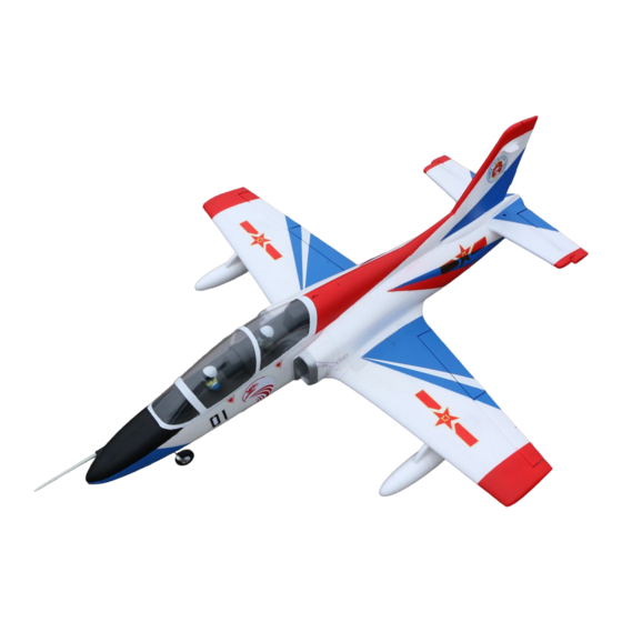
K-8 Karakorum Jet Trainer
64mm EDF RC JET
SPECIFICATIONS
Wingspan: 930mm
Length: 1026mm (without pitot tube)
Dry weight: 530g
Flying weight: 1150g (Full loading)
Wing loading: 72.6g/dm²
4S Version: 2200-2600mAh 4S Lipo; 6S Version: 2200-4200mAh 6S Lipo.
KIT
Shock Absorber
KIT
Landing Gear
9g Servo x 8 (Installed)
RECOMMENDED BATTERY
KIT TYPE
KIT + Servos
KIT
9g Servo x 8 (Installed)
40A ESC x 1 (Installed)
4S: 2840-3200KV 64mm EDF (Installed)
6S: 2840-2300KV 64mm EDF (Installed)
ELECTRONIC
Power System: 6S/4S 64mm EDF x 1
ESC: 40A ESC x 1
Servos: 9g servos x 8
Battery: 6S/4S Lipo
Radio: 6 Channel TX and RX
PNP
Advertisement
Table of Contents

Related Manuals for FLYFANS K-8 Karakorum Jet Trainer


Summary of Contents for FLYFANS K-8 Karakorum Jet Trainer
- Page 1 K-8 Karakorum Jet Trainer 64mm EDF RC JET SPECIFICATIONS ELECTRONIC Wingspan: 930mm Power System: 6S/4S 64mm EDF x 1 Length: 1026mm (without pitot tube) ESC: 40A ESC x 1 Dry weight: 530g Servos: 9g servos x 8 Flying weight: 1150g (Full loading) Battery: 6S/4S Lipo Wing loading: 72.6g/dm²...
- Page 2 CONTENTS OF KIT 9. Landing Gear L*1 16. Front Wheel Pushrods*1 1. Fuselage*1 10. Landing Gear R*1 17. Screws for wings*4 (Silver) 2. Left Wing*1 3. Right Wing*1 18. Screws for Horizontal 11. Drop Tank Pylon * 2 stabilizer*2 4. Horizontal (Installed for Kit+S/PNP) Stabilizer*1 19.
- Page 3 Model Assembly Horizontal stabilizer Servo Set 9g servo to neutral point and screw on Servo arm. Glue the servo into the slot on the Hori- zontal Stabilizer. Suggested cable length is 15cm. NOTE: Require 1 normal and 1 reverse 9g Servo. 2.
- Page 4 Same procedure with the other Wing. Rudder Servo Set 9g servo to neutral position and screw on Servo arm. Glue the servo into the slot on the Rudder. Ajust pushrods length then link the Servo arm and Control horn. We recommend use the 2 holes on Caution: Servo arm.
- Page 5 9. Install Horizontal Stabilizer onto fuselage. Tighten the screws with 2.5mm hexagon key. EDF & ESC 10. Install ESC into the ESC compartment and connect the 3 power leads to the EDF. Test the EDF to ensure the blades spin in the correct direction.
- Page 6 Landing gear Installation 13. Install the main landing gears, ensuring that the springs Scale 像真 are facing forward. • For a scale look, Position the main landing gears with the wheels inboard. • For a more stable taxiing, position the wheels outboard.
- Page 7 Main Wing installation 16. Insert the carbon spar into fuselage. Following the labels in the servo leads, connect the Aileron and Flap servos. 17. Install both wings and secure with screws. Accessories 18. Slide both Drop Tanks into the wing Pylon 19.
- Page 8 Flight Setup Check the C.G. The Center of Gravity (CG) location is 63mm from the leading edge of the main wing (as shown) with the battery pack installed. The center of gravity can be adjusted by moving the battery forward or aft. Model Setup Model Setup We recommend using dual rates for a better flying experience.
Need help?
Do you have a question about the K-8 Karakorum Jet Trainer and is the answer not in the manual?
Questions and answers