
Related Manuals for GreenValley LiAir 50N


Summary of Contents for GreenValley LiAir 50N
- Page 1 LiAir 50N User Guide • GreenValley International Inc. –––––– LiAir 50N UAV LIDAR System User Guide COPYRIGHT © 2017-2021 GreenValley International Inc. Page 1...
- Page 2 LiAir 50N User Guide • GreenValley International Inc. GreenValley International Inc. (GVI) reserves all right for final explanation, and at its sole discretion, to change, modify, and remove portions of this document. No Part of this document may be reproduced or transmitted in any form or by any means, electronic, mechanical, photocopying, recording, or otherwise, without prior written permission of GreenValley International Inc.
- Page 3 LiAir 50N User Guide • GreenValley International Inc. About This Guide This document is a general introduction and operation guide for GVI’s LiAir 50N lightweight UAV LIDAR mapping/survey systems. As we continue to update and improve the product, you may find some differences between the contents of this document and your LiAir 50N system.
-
Page 4: Table Of Contents
2.5.4 Integrated Camera (Optional) ............................13 3. Equipment Setup and Operation Procedure ..............13 3.1 Assemble and install LiAir 50N Payload Mounting Kit ............... 13 3.2 Set up GNSS Base Station ........................14 3.3 LiAir 50N Setup and Operation (DJI M300) ................... 16 4. -
Page 5: Read This First
50N at the time of purchase or in a productive case authorized for use by GVI. Clean the product thoroughly after each use. Do NOT use water. When not in use, store LiAir 50N system and accessories in a cool and dry environment. Page 5... -
Page 6: Liair 50N System
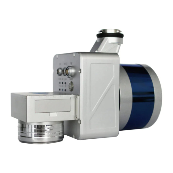
2. LiAir 50N System 2.1 About LiAir 50N UAV-LIDAR system is a light-weighted (1.4 kg incl. camera) and 3D surveying and mapping instrument designed to be mounted to multi-rotor aerial platforms (DJI M300 & DJI M600). LiAir 50N provides accuracy point cloud data for users in various industries including topographic surveying, forestry, vegetation management, power line inspection, and many more. -
Page 7: Technical Specification
Scanner are registered together to a common coordinate system and georeferenced using the POS data. ➢ LiAir 50N data are saved to the System Control and Storage Unit and can be downloaded from the device after data collection has been stopped. -
Page 8: Liair 50N System Components
2.5 LiAir 50N System Components 2.5.1 Laser Scanner The Velodyne’s Puck LiDAR sensor is the LIDAR sensor integrated into the LiAir 50N Ultralight system. The LiDAR sensor transmits an ultrashort pulse of NIR energy that strikes objects within the Laser Scanner’s field of view and reflects back to the Laser Scanners receiver as a light echo. -
Page 9: Position And Orientation System (Pos)
Global navigation satellite system, or (GNSS) on LiAir 50N supports, mainly includes GPS, GPS (the U.S.), Galileo satellite navigation system, (Europe), BeiDou Navigation Satellite System (China), and GLONASS (Russia). The GNSS of LiAir 50N includes the aviation GNSS antenna and the base station antenna. -
Page 10: Control And Storage Unit
Storing the data. The SD card inside is used to store the data of IMU, camera, and device log. b) LiAir 50N Ultralight power and data ports, ON/OFF button, GNSS antenna ports, as well as indicator LEDs are located on the front and sides of the LiAir 50N’s main body:... - Page 11 5 – CONFIG - Debugging port that is reserved for use by the system manufacturer. 6 – Network Port (marked as LAN): This port is used to connect the LiAir 50N Ultralight to a ground control computer where users can adjust system and data collection settings through a browser- based user interface.
- Page 12 Detailed Figures and Tables describing LiAir 50N Ultralight Indicator LED panel: Figure 3. Partial View of LiAir 50N Ultralight Control Panel Table 4. Detailed explanations of Indicator LED light statuses displayed on the LiAir 50N Ultralight Control Panel Explanation of Indicator LEDs...
-
Page 13: Integrated Camera (Optional)
This section of the LiAir 50N Ultralight User guide describes the recommended equipment setup and operation procedures. 3.1 Assemble and install LiAir 50N Payload Mounting Kit Assembly and installation of the LiAir 50N Ultralight mounting kit can be found in the Quick Guide of Assemble and Mount LiAir 50N Payload section. Page 13... -
Page 14: Set Up Gnss Base Station
LiAir 50N User Guide • GreenValley International Inc. 3.2 Set up GNSS Base Station (1) Select an open area for positioning Place the GNSS antenna at an open area in order to ensure the antenna can get access to the GNSS satellites as many as possible. - Page 15 LiAir 50N User Guide • GreenValley International Inc. Figure 5. Power and USB Interface (3) Calculate the antenna height Measure the oblique distance from antenna bottom edge to the ground for more than three-times, take the mean value as H1.
-
Page 16: Liair 50N Setup And Operation (Dji M300)
4. Connect a Ground Control computer to LiAir 50N system via Network Cable When connecting a Ground Control Computer to the LiAir 50N system for the first time follow this procedure to set up the Ethernet Connection: Page 16... - Page 17 LiAir 50N User Guide • GreenValley International Inc. a. Attach the LEMO connector of the Network Cable to the LAN port located on the front panel of the LiAir 50N main body and the opposite end of the Network Cable to the Ground Control Computer’s Ethernet port.
- Page 18 LiAir 50N User Guide • GreenValley International Inc. 6. Set up collection parameters Before start scanning: a) Skip this step if there’s no needs for resetting, and the previous parameters setting up have been already memorized as a reference. b) However, if there is a need for resetting, settings of LIDAR and camera could be considered as a priority.
- Page 19 Press ON/OFF button for 0-2 seconds. The DA LED light on the front panel of the LiAir 50N Main Body will turn on to indicate that a new Project has been created and IMU data collection has begun. Note that Laser Scanner data collection will start only after use specified Control Mode (Flight Speed or Flight Height) requirements are met.
-
Page 20: Data Download
Power off UAV 4. Data Download 4.1 Download LiAir 50N Data This section provides users with instructions on how to transfer Project data from the LiAir 50N system if integrated camera to another device. Each LiAir 50N will contain an IMU+GNSS file, a cam file ( data is available ), a log file, as well as the laser scan data. -
Page 21: Download Base Station Data
LiAir 50N User Guide • GreenValley International Inc. 9. Copy the Project folder(s) from the LiAir 50N’s internal storage to a target directory located on the connected computers internal or external data storage device. it is a good practice to make sure the LiAir 50N’s Prior to data collection SD card has sufficient memory space available. -
Page 22: Data Processing
LiGeoreference User Handbook section. 5.1 Project Folder Structure LiAir 50N will automatically create a project for the mission in SD card of laser scanner and associated subfolders to store incoming data on LiAir 50N’s internal storage device. The organization structure of the project file is shown in the figure below. - Page 23 LiAir 50N User Guide • GreenValley International Inc. Project folder is named with UTC Time, including: Base folder is used to store the ground GPS base station data. Calibrate folder is used to store calibrated files (*.cal). Please notice that: do not remove or delete this folder, otherwise, the performance of georeferencing will fail.
-
Page 24: Data Post-Processing
LiAir 50N User Guide • GreenValley International Inc. 5.2 Data Post-processing 5.2.1 Open Project LiGeoreference project file Click “File” icon on the toolbar to open (.live) through “Browse” icon, and users can also open the project file via “Recent Projects” icon which refers to history project opened before. -
Page 25: Select And Configure Parameters
LiAir 50N User Guide • GreenValley International Inc. Figure 14. Trajectory Display 5.2.2 Select and Configure Parameters Before undertaking post-processing procedure, users can use the "Settings" function to set the calculation parameters, including laser settings, camera settings, pos process and target coordinate system settings. - Page 26 Pos Processing Settings LiGeo software has pos calculation and point cloud calculation functions. Users could directly use LiGeo software to calculate LiAir 50N’s trajectory, or choose to use other third-party software to perform pos processing procedure. Using LiGeo to Perform Pos Processing Procedure Select the "Pos Processing"...
- Page 27 LiAir 50N User Guide • GreenValley International Inc. Figure 16. Pos Setting Interface (1) Select LiNav processing mode (2) Select the processing mode according to the length of the trajectory. It is recommended to use the general mode. When the length of the trajectory is more than 10 km, the long baseline mode can be selected.
- Page 28 LiAir 50N User Guide • GreenValley International Inc. Figure 17. “Rinex” Display Interface If the local base station format is Log format, select the Novatel option. Figure 18. “Novatel” Display Interface (5) Enter the Base Station Coordinates - When there is no precise base station coordinate, users could select "Average" mode. And the positioning principle is single point positioning, which leads to meter-level errors between the point cloud coordinates calculated by this method and the true coordinates.
- Page 29 LiAir 50N User Guide • GreenValley International Inc. Figure 19. “Select from Favorites” Display Interface - Analyze from the data header: some base station files and base station coordinates are stored in the header file. “From Header” option needs to be clicked when users want to use this function. For example, Cloud Trajectory base station is normally stored in this mode.
- Page 30 LiAir 50N User Guide • GreenValley International Inc. Laser Setting Normally, the user does not need to change the parameters of the laser setting interface. If users want to limit the output power range by reflectivity, distance and scanning angle, users could change the range via clicking “Filter”...
-
Page 31: Georeferencing Point Cloud Data
LiAir 50N User Guide • GreenValley International Inc. Figure 23. “Camera Setting” Display Interface 5.2.3 Georeferencing Point Cloud Data 5.2.3.1 Select Georeference Range Users could select the range to be georeferenced as needed. And there are two modes to be selected, including "trajectory selection"... - Page 32 LiAir 50N User Guide • GreenValley International Inc. Figure 24. “Select On Trajectory” Display Interface (2) If needed to select multiple trajectories, then repeat the above operation, and the selected trajectory segments will be displayed in the cutting table at the lower left corner.
- Page 33 LiAir 50N User Guide • GreenValley International Inc. Figure 25. “Select On Trajectory” Display Interface 5.2.3.2 Select Processing Module After opening the project, LiGeo will select “POS Process” and “Georeference” module by default. Users could check and rechoose the function modules as needed.
-
Page 34: Data Quality Assessment
LiAir 50N User Guide • GreenValley International Inc. Figure 27. “Start” Display Interface 5.2.4 Data Quality Assessment If the user needs to view the “Trajectory Report” and the “Image Overlap Report”, click the "Trajectory Plot" (or " Trajectory Report ") or “Image Overlap Report” (only suitable for devices with cameras) under the "Tools"... - Page 35 LiAir 50N User Guide • GreenValley International Inc. Figure 29. “Report" Display Interface • Satellites Number: Click to open the plot to show the relation between number of satellites, which can be reached, and the GPS time. This tool is used to show the number of satellites can be reached by the device each time during the data acquisition.
- Page 36 LiAir 50N User Guide • GreenValley International Inc. Figure 30-1 Trajectory Report - Satellite Numbers • Floating/Fixed ambiguity status: Click to show the plot of ambiguity resolution status. This is used to show the situation of cycle ambiguity resolution. If the status is shown as green on the plot, it means the cycle ambiguity resolution is fixed.
- Page 37 LiAir 50N User Guide • GreenValley International Inc. Figure 30-3 Trajectory Report - PDOP File Data Coverage: Click to show the plot of data coverage situation. This is used to show the data coverage relation among base station data, IMU data, and GNSS data of the moving device.
- Page 38 LiAir 50N User Guide • GreenValley International Inc. shows the changes in Pitch direction. While the blue line shows the changes in the heading direction. Figure 30-5 Trajectory Report - Estimated Attitude Accuracy Estimated Position Accuracy: Click to plot the position accuracy. The X-axis shows the GPS time.
- Page 39 LiAir 50N User Guide • GreenValley International Inc. Estimated Velocity Accuracy: Click to plot the velocity accuracy. The X-axis shows the GPS time. The Yaxis shows the velocity accuracy. Red line is for velocity accuracy in East direction. Green line shows the velocity accuracy in North direction. While the blue line shows the position velocity in height direction.
- Page 40 LiAir 50N User Guide • GreenValley International Inc. Attitude Separation: Click to show the plot of attitude separation. This plot is used to show the difference among the angles in Roll, Heading, and Pitch directions during the forward-backward processing. The smaller the value is, the better the matching degree of the forward-backward processing is.
- Page 41 LiAir 50N User Guide • GreenValley International Inc. Velocity Profile: This plot shows the changes in velocity during the data acquisition. Red line is for the changes in East direction. Green shows the changes in North direction. While the blue line shows the changes in up direction to the ground.
- Page 42 LiAir 50N User Guide • GreenValley International Inc. Figure 31. “Image Overlap Report" Display Interface Page 42...
-
Page 43: Special Notes
LiAir 50N User Guide • GreenValley International Inc. 6. Special Notes Here are some special Note to pay attention while operating LiAir 50N. GVI has compiled these Note based on experiences and feedback from customers. The following points out details that seem small or insignificant but can, however, lead to issues that may be difficult or impossible to rectify post mission if left unchecked. - Page 44 LiAir 50N User Guide • GreenValley International Inc. Tampering with the product is strictly prohibited and will void the Product Warranty. Any repair, modification, or upgrade must be performed by GVI technician or authorized service provider. This product is a high-precision mapping and surveying instrument that must be handled with care.
Need help?
Do you have a question about the LiAir 50N and is the answer not in the manual?
Questions and answers