Advertisement
Quick Links
Advertisement

Related Manuals for store away salcombe


Summary of Contents for store away salcombe
- Page 1 Assembly Instructions...
- Page 3 fold away Thank you for purchasing a F old Away Petite cabinet. If y ou have any questions regarding assembl y please contact us on 0800 048 8606. petite HINGE (H2) x 4 BRACKET CASTER (C2) x 14 (AB1) x 12 SCREW (30-15C) x 24 SCREW...
- Page 4 STEP 1 Attach six of the casters (C2) to the M-BOT as indicated using screws 35-17D. M-BOT 35-17D The casters attach to this side of the panel (the side showing the part label) STEP 2 Screw a cam bolt into each of the four holes indicated. These need to be screwed into the opposite side to the casters.
- Page 5 STEP 4 Attach the both of the M-B1 panels, M-B2 and both of the M-CD together as indicated. Once slotted together ensure you tighten the cam locks. STEP 5 Attach the section you have already assembled to the M-BOT as shown below and tighten the cam locks.
- Page 6 STEP 6 Screw a Cam Bolt (CB1) into each of the holes indicated below screw in to this point M-RHS M-LHS STEP 7 35-17D Attach the brackets (AB1) to the left and right hand sides using screws (35-17D) as shown below. M-LHS M-RHS...
- Page 7 STEP 8 Attach the M-LHS and the M-RHS to the assembled sections. Secure by tightening the cam locks in the both of the backs (M-B1) and the base (M-BOT). STEP 9 Fix the brackets that you have already attached to the sides to the base using screws (35-17D) as shown below.
- Page 8 STEP 10 Screw a Cam Bolt (CB1) into each of the holes indicated below M-TOP STEP 11 Attach the M-TOP to the assemble main section. Secure by tightening the cam locks in the both the M-CD’s and the M-LHS and the M-RHS. M-TOP...
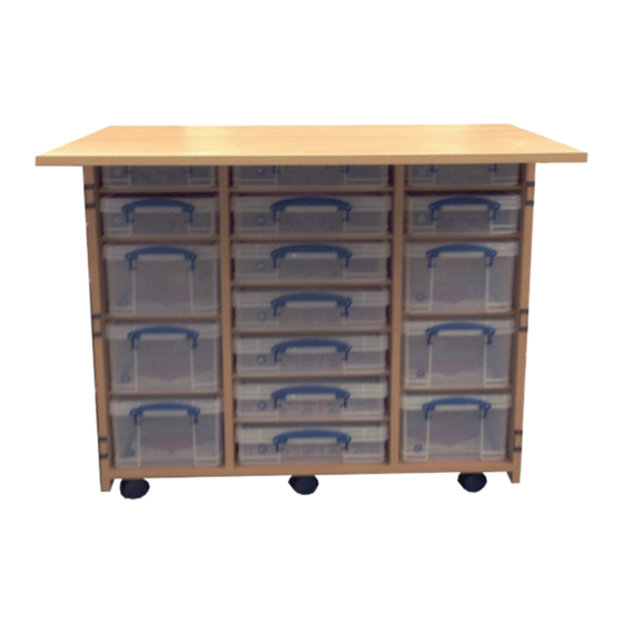
- Page 9 STEP 10 Insert shelf pegs and shelves to fit the storage boxes as shown below. Start from each section from the bottom and work upwards when fitting the shelves and boxes to ensure the correct shelf spacing. STEP 11 Attach the remaining eight casters (C2) to the D1-BOT and the D2-BOT using screws 35-17D as shown below.
- Page 10 STEP 13 Screw a cam bolt into each of the four holes indicated on the D1-CD Panel. Two need into one side of the panel and two into the opposite side. D1-CD D1-CD (SIDE 1) (SIDE 2) STEP 14 Screw a cam bolt into each of the two holes indicated on the D2-CD Panel.
- Page 11 STEP 16 Screw a Mini Cam Bolt (CB2) into each of the holes indicated below with a red circle. Screw a Cam Bolt (CB1) into each of the holes indicated below with a blue circle D1-TOP D2-TOP screw in to this point STEP 17 Screw a Cam Bolt (CB1) into each of the holes indicated below...
- Page 12 STEP 20 STEP 19 Attach the section that you have already assembled (D1-CD & 2 x D-B1 panels) to the D1-TOP and D1-BOT as shown below. Attach by tightening the locks that will have been pre-in- stalled into the panels. D1-TOP D1-BOT STEP 21...
- Page 13 STEP 22 Fix the brackets that you have already attached to the sides to the bases of both the door sections using screws (35-17D). For detailed instructions refer to step 9. STEP 23 Screw a Cam Bolt (CB1) into each of the holes indicated below. Attach the door knobs. Fit the front door panels to the assembled sections and tighten the cam locks to secure.
- Page 14 STEP 25 D2-TOP Slide the D2-CD into the door section and tighten the cam locks in the back and also the locks in the D2-CD to secure in place. D2-BOT D2-BOT STEP 26 D2-TOP Screw a Mini Cam Bolt (CB2) into the two holes on the outer surface of the D2-LHS as indicat- ed.
- Page 15 STEP 28 Insert shelf pegs and shelves to fit the storage boxes as shown below bottom and work upwards when fitting the shelves and boxes to ensure the correct shelf spacing. . Start each section from the Insert the acrylic into the slots in the Rack Shelves and D2-BOT panels and then use SP2 shelf pegs to secure the Rack Shelves into the unit.
- Page 16 Freephone: 0800 048 8606...
Need help?
Do you have a question about the salcombe and is the answer not in the manual?
Questions and answers