
Subscribe to Our Youtube Channel
Related Manuals for WAHLAP TECH PUSHING POINTS


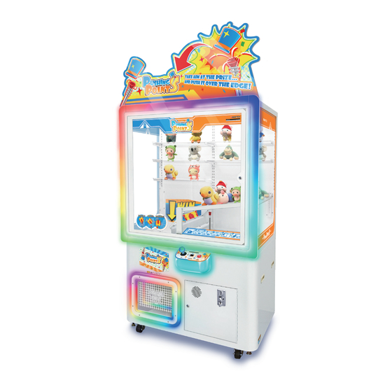
Summary of Contents for WAHLAP TECH PUSHING POINTS
- Page 1 Ver.1.00 For safety reasons, please read the manual first before plugging in machine. Please keep this manual properly for convenient reference as needed.
-
Page 3: Table Of Contents
Table of Contents About This Manual 1. Safety Precautions ..........1 1.1 Warning Stickers ............1.2 Placing Site ............. 1.3 Safety Precautions ............1.4 Precaution during Play ............ 1.5 Transporting and Moving ..........1.6 Installing and Placing ............. 1.7 Caution & Warning Stickers .......... - Page 4 4.1.1.7 Data Clear ..........4.1.1.8 Rom Version ..........4.2 Error Display ............4.3 Error List ............... 4.4 Sound List .............. 4.5 Main-board DIP SW setting ..........4.6 Displayed contents on the digital board at the time of coining ..... 5. Maintenance and Service ......... 39 5.1 Maintenance and service ..........
- Page 5 5.2.32 Replacement of prize baffle .......... 5.2.33 Specification for height-adjusting net ........5.2.34 Specification for the height of the ramp net ......5.2.35 Descriptions for damping-adjustable hinge ......5.2.36 Description for power socket ......... 5.2.37 Description for LCD position and operation steps ......
- Page 6 6.7.4 Horizontally-moving motor components(PP-0504000) ..... 6.7.5 Total jacking-rod components(PP-0505000) ......6.7.5.1 Jacking-rod fixing-wheel components(PP-0505000-A) ....6.7.5.2 Jacking-rod motor components(PP-0505000-B) ...... 6.7.5.3 Jacking-rod sensor components(PP-0505000-C) ....6.7.5.4 Jacking-rod components(PP-0505000-D) ......6.8 Ramp net components(PP-0700000) ........6.8.1 Net components(PP-0701000) ........6.8.2 Prize ramp-panel components(PP-0702000) ......
-
Page 7: Safety Precautions
1. Safety Precautions 1.1 Warning Stickers In order to avoid injury to related people and damage to property, please observe the followings: PLEASE READ FIRST The following marks can be used to indicate the magnitudes of risk and damage caused by ignorance or improper operation: Warning means “may result in serious injury or death”... -
Page 8: Safety Precautions
1.3 Safety Precautions The owner shall pay attention to the followings when placing, checking and repairing machine to insure player’s security and avoid damage: Warning please check the voltage is 110V or 220V before the machine connectes to the power supply,or it may cause a fire or electric shock. Make sure to plug the game into 110V or 220V main outlet to avoid fire and electric shock. -
Page 9: Precaution During Play
1.4 Precautions during Play Caution In order to avoid injury and accident during play, the following people shall not play the game: People who are injured or less mobile. Person with poor health condition, such as hypertension or heart disease. Person wearing high-heeled or slippery shoes. -
Page 10: Installing And Placing
1.6 Installing and Placing Pay attention to the following when placing the machine. Caution Place the machine on the flat and slip resistant area. Use the adjusters to fix the machine (See diagram 1) 1.Loosen the nuts for the adjusters (clockwise), tighten the bolts with a wrench (clockwise). 2.Tighten the nut firmly(counter clockwise) and fix it well. -
Page 11: Caution & Warning Stickers
1.7 Caution & Warning Stickers... -
Page 12: Product Description
2. Product Description 2.1 Product Specification Location Indoor Only Dimension 1220(W)×795(D)×2566(H) Rated Voltage 220V Frequency 50Hz Power Consumption 160 W Game-machine weight 210 kg Temperature Range 。 5~40 Max size of prize 265(W)×350(D)×300(H) Max weight of prize 1 kg Prize net size 560(W)×590(D) 1220mm Note:Adjustable height... -
Page 13: Overview
2.2 Overview Side View Rear View Top View Bottom View... -
Page 14: Parts Name
2.3 Parts Name POP components Large door-frame acrylic components Displaying-board components components Large transparent-door components Moving-part Prize-outlet mask components components Hardware frame Prize outlet-door Control-panel components Speaker Coin-acceptor Rear door plank AC-BOX Side-door... -
Page 15: Shipment List
2.4 Shipment List Modes of packing 条形 码 粘贴 处 Note:Fix to the top of the game-machine with bubble film & plastic wrap. Note:Fix to the front door with plastic wrap. Note:1. Wrap it with plastic wrap. 2. Fix to the screen with cable ties. ... -
Page 16: Packing List
2.5 Packing List Please check the following items after purchasing our product. If any part missing or damaged, please contact our sales person! Description Specification Quantity Remarks Power cord 3m(1.0mm ) 250V (two-end three-pin) Lock of same size B17 key,No.6687 B17 key Large top 5052-O... -
Page 17: Instructions For Installation
2.6 Instructions for installation Fix POP components to the top of the game-machine with 5 screws. Remove POP components and screw it onto the top of the game-machine. Note:X/Y axes of moving parts are provided with 2 cable ties respectively! Warning Before the game-machine is powered on, cut off the cable ties at this position (for fixing X/Y axes of moving parts during transportation). -
Page 18: Warranty
2.7 Warranty Scope Inquiry regarding product can be assisted for free. The warranty scope for consumables and durables may differ from product to product. Please contact our after-sales service center for detailed information. The right of final interpretation is reserved. Exclusive Damage caused by force majeure such as god will. -
Page 19: Game Description
3. Game Description 3.1 Appearance Design The color of "PUSHING POINTS" is mainly white and the game-machine is designed very simply and elegantly. After it is powered on, its lamp is bright and dazzling. The game-machine can display different styles by replacing 3 pieces of PVC. In the gaming area, there are 5 layers of prize-racks. -
Page 20: Modification About Game-Machine Top/Prize Slide-Way
5. When the prize is jacked by the jack- 6. The player can get the prize at the prize ing-rod, the player can get the prize outlet! successfully! 3.3.1 Modification about game-machine top/prize slide-way 3.3.1 Modification about game-machine top/prize slide-way Its top is provided with screws and nuts that can be modified into various operating methods. - Page 21 The prize slide-way is provided with screws and nuts that can be modified into various The prize slide-way is provided with screws and nuts that can be modified into various operating methods. operating methods. The prize slide-way is provided with 8 fixable positions. The prize slide-way is provided with 8 fixable positions.
-
Page 22: Test And Setting
4. Test and Setting 4.1 Test Mode 【Basic operation and service-panel】 1. The service-panel can be seen when the right access door is opened. 2. Turn on [TEST]. The various data will be displayed and the test-mode can be entered. 3. -
Page 23: Top Menu
4.1.1 TOP MENU 1. By pressing [↑] and [↓] , the arrow will move to select the corresponding item. 2. Press [SETTING] to confirm and the selected data or test mode will be entered. For main menu, refer to P1 ※The purpose of this feature is used to test the rationality of prize configuration before operation. -
Page 24: Meter
4.1.1.2 METER 1. The service-panel can be seen when the right access door is opened. 2. Turn on [TEST]. The various data will be displayed and the test-mode can be entered. 3. By pressing [↑] and [↓] , the arrow will point to "METER". Press [SETTING] to confirm. 4. -
Page 25: Game History
4.1.1.3 GAME HISTORY 1. The service-panel can be seen when the right access door is opened. 2. Turn on [TEST]. The various data will be displayed and the test-mode can be entered. 3. By pressing [↑] and [↓] , the arrow will point to “GAME HISTORY”. Press [SETTING] to confirm. -
Page 26: Error History
4.1.1.4 ERROR HISTORY 1. The service-panel can be seen when the right access door is opened. 2. Turn on [TEST]. The various data will be displayed and the test-mode can be entered. 3. By pressing [↑] and [↓] , the arrow will point to “ERROR HISTORY”. Press [SETTING] to confirm. -
Page 27: Setting
4.1.1.5 SETTING 1. The service-panel can be seen when the right access door is opened. 2. Turn on [TEST]. The various data will be displayed and the test-mode can be entered. 3. By pressing [↑] and [↓] , the arrow will point to “SETTING”. Press [SETTING] to confirm. 4. - Page 28 6. Select the item to be set by pressing [↑] and [↓]. 7. Change the setting-value of the selected item by pressing [←] or [→]. For set item, refer to P2 For set item, refer to P3 SEGA Initial Item Name Contents Set Range Recomended...
- Page 29 8. Select the item to be set by pressing [↑] and [↓]. 9. Change the setting-value of the selected item by pressing [←] or [→]. For set item, refer to P4 For set item, refer to P5 Initial Item Name Contents Set Range value...
-
Page 30: I/O Test
4.1.1.6 I/O TEST 1. The service-panel can be seen when the right access door is opened. 2. Turn on [TEST]. The various data will be displayed and the test-mode can be entered. 3. By pressing [↑] and [↓] , the arrow will point to “I/O TEST”. Press [SETTING] to confirm. 4. - Page 31 Test content and operation Contents >LEFT/RIGHT -- - Test of left/right movement of the jacking-rod Detect the sensor-status when moving to the left or Press [→] to move to the right right Press [←] to move to the left (O:blocked indicator、 Move to all the directions by using the joystick.
-
Page 32: Shutter Test
4.1.1.6.2 SHUTTER TEST 1. Repeat steps 1-2 in 4.1.1.6.1. By pressing [↑] and [↓] , the arrow will point to “SHUTTER TEST”. Press [SETTING] to confirm. 2. Press [→] or move the sealing-plate upward or to the right by using the joystick on the control panel to open the sealing-plate. -
Page 33: Switch&Sensor Test
4.1.1.6.4 SWITCH&SENSOR TEST 1. Repeat steps 1-2 in 4.1.1.6.1. By pressing [↑] and [↓] , the arrow will point to “SWITCH&SENSOR TEST”. Press [SETTING] to confirm. 2. When a button is pressed, it is displayed in shape of (O:ON、-:OFF). Button/sensor test interface Item Name Contents Status of service-panel button and prize count button... -
Page 34: 7Seg Test
LED SN Item name (part) ALL OFF 02~05 Button(Jacking-up) Front-frame LED (right) 、Prize outlet (red) 06~09 Front-frame LED (right) 、Prize outlet (green) Front-frame LED (right) 、Prize outlet (blue) Front-frame LED (right) 、Prize outlet (white) Front-frame LED (left) 、Control-panel LED 06~09 (red) Front-frame LED (left) 、Control-panel LED (green) -
Page 35: Aging Test
4.1.1.6.8 AGING TEST 1. Repeat steps 1-2 in 4.1.1.6.1. By pressing [↑] and [↓] , the arrow will point to “AGING TEST”. Press [SETTING] to confirm. 2. Start the aging-test by pressing [SETTING]. 3. During the aging-test, press [SETTING] to stop the aging-test. Aging-test Item Name Contents... -
Page 36: Data Clear
4.1.1.7 DATA CLEAR 1. Repeat steps 1-2 in 4.1.1.6.1. By pressing [↑] and [↓] , the arrow will point to “DATA CLEAR”. Press [SETTING] to confirm. 2. Select the items to be initialized by the arrow by pressing [↑] and [↓]. 3. -
Page 37: Error Display
4.2 Error Display When an error occurs, "E-" and corresponding error is displayed alternately on the digital board. Meanwhile, the error is displayed on LCD and ERROR HISTORY will be saved. Example: When error 1 occurs Digital board LCD error menu displayed alternately When there are 2 errors and the player can't tell which one is correct, the digital... - Page 38 Error Error Causes Way to remove Code Meaning Display When the coin-sensor of the Take out the coins stuck in the E01 COIN JAM coin-acceptor is ON for two seconds, COIN JAM ERROR coin-acceptor. it cannot be turned OFF. The solution is to change [TILT]setting.
- Page 39 Error Error Causes Way to remove Code Meaning Display The bank limit-sensor does not Jacking-rod Bank limit-sensor E31 BACK LIMIT sense within 8 seconds when the The bank limit-sensor malfunctions. error jacking-rod moves backward. When the jacking-rod moves The moving-forward/backward Jacking-rod forward, the moving-forward/ motor, the moving-forward/...
- Page 40 Error Error Causes Way to remove Code Meaning Display Sealing-plate When the sealing-plate is (motor side) opened, the opening The opening The opening limit-sensor malfunctions. E40 OPEN LIMIT limit-sensor does not limit-sensor gives sense within 5 seconds. an error Sealing-plate When the sealing-plate is (motor side) closed, the closing...
- Page 41 The closing limit-sensor E 41 The sealing-plate motor E 41 E 40 & The opening limit-sensor TILT E 40 E 02 ※ TILT adjust guide P.76 The opening-sensor E 42 The prize-block gives an error E 50 The closing limit-sensor E 43 E 97 E 99...
- Page 42 【Calibrating procedure of optical-eye box】 This game-machine is provided with 3 optical-eye boxes. They are A optical-eye box, B optical-eye box and C optical-eye box, as shown in the right figure. In the event that no prize is detected or E50 error is given, A, B and C optical-eye boxes can be calibrated separately.
-
Page 43: Sound List
4.4 Sound List Conditions Category Item Name Usage of usage Game BGM Play BGM while playing LOOP Played music for getting the prize JINGLE Played cheers for getting the prize successfully successfully JINGLE Jacking-up failure (collision) sound Regreted sound for not getting the prize Longitudinal-moving sound of sound of the jacking-rod moving jacking-rod (upper) -
Page 44: Main-Board Dip Sw Setting
4.5 Main-board DIP SW setting DIP SW Function Used in OFF Used in OFF Used in OFF Used in OFF Used in OFF Displayed contents on the digital board at the Displaying the existing coins Displaying the existing game time of coining Used in OFF Used in OFF All are OFF by default... -
Page 45: Maintenance And Service
5. Maintenance and Service 5.1 Maintenance and service Even though the machine works normally for a long time, the fault will occur. Therefore, please perform routine check and maintenance concerning the following to ensure a long-term use. External Inspection Stick “Warning” stickers correctly, keep it legible. Firmly tighten the bolt for each adjuster. -
Page 46: Part Replacement
5.2 Part Replacement 5.2.1 Change LED with casing 1. Open the acrylic door with the key, untie the cable ties and pull out the terminal corresponding to the damaged LED. 2. Remove shelled LEDs from 2 card-slots and reinstall in a reverse order after replacing. Top: DC12V white indicator 60 L=1100mm Both sides: DC12V white indicator 60 L=1000mm Right: DC12V white indicator 60 L=500mm... -
Page 47: Change Door-Frame Acrylic Soft-Lamp-Bar
5.2.3 Change door-frame acrylic soft-lamp-bar 1. Assess the damaged position of soft light-bars on the door-frame and there are 2 soft light-bars, which are on the left-side and right-side. 2. If the soft light-bar on the right side is damaged, use the key to open the acrylic door, remove 2 nuts that fix the iron-sheet and remove the iron-sheet. -
Page 48: Change Prize-Outlet Soft-Lamp-Bar
7. Remove the soft light-bar, reinstall in a reverse order after replacing. Soft-lamp-bar Both sides: DC12V RGB60 lamp L=2050mm 5.2.4 Change prize-outlet soft-lamp-bar 1. Remove 8 screws that fix the mould-weight at the prize outlet and remove the mould-weight and acryl at the prize outlet. 2. - Page 49 3. Use the slot-type screwdriver to fix the joystick. At the same time, rotate the joystick-ball counterclockwise and take out the black plastic sheeting. 4. Remove 4 screws to fix the acryl. 5. Turn the acryl on the other-side, pull out the corresponding terminal and remove the acryl. 6.
-
Page 50: Change Control-Panel Joystick
5.2.6 Change control-panel joystick 1. Turn off the game-machine. Open the acrylic door with the key, remove the screen and 2 screws that fix the service-hatch cover-plate and remove the service-hatch cover-plate. 2. Remove 4 screws that fix the control panel and remove the control panel. 3. -
Page 51: Change Control-Panel Button
7. Remove 4 screws to fix the joystick, cut off the cable tie, pull out the corresponding terminal and remove the joystick, reinstall in a reverse order after replacing. JS-EPCG-BU-45-CB 5.2.7 Change control-panel button 1. Remove 4 screws to fix the acryl. 2. -
Page 52: Replacement Of Left/Right Sensors
3. Remove 4 screws that fix the digital display board, cut off the cable tie, pull out the corresponding terminal and remove the digital display board, reinstall in a reverse order after replacing. WL_KC_7SEG_V1.0 5.2.9 Replacement of left/right sensors 1. Turn off the game-machine and remove the screen. There are 2 sensors on the horizontal guide-rail. -
Page 53: Replacement Of Front/Rear Sensors
5.2.11 Replacement of front/rear sensors 1. Turn off the game-machine. Open the acrylic door with the key, remove the screen,there are 2 sensors on the longitudinal rail. 2. Remove the screw to fix the sensor, pull out the corresponding terminal and remove the sensor, reinstall in a reverse order after replacing. -
Page 54: Replacement Of Colliding-Sensors
5.2.14 Replacement of colliding-sensors 1. Turn off the game-machine. Open the acrylic door with the key, remove the screen,there is 1 sensor on the jacking-rod, remove 2 screws to fix the lifting electric-eye fixing-iron and rermove the lifting electric-eye fixing-iron. 2. -
Page 55: Replacement Of Optical-Eye Box
5.2.17 Replacement of optical-eye box 1. Turn off the game-machine. Open the acrylic door with the key, remove the screen, remove 4 nuts to fix the eyelet fixing-iron. 2. Remove 4 nuts to fix the optical-eye box, pull out the corresponding terminal and remove the optical-eye box, reinstall in a reverse order after replacing. -
Page 56: Replacement Of Longitudinally-Moving Motor
3. Remove 4 screws that fix No. 2 motor iron on the prize door. 4. Remove 4 screws that fix No. 1 motor iron on the prize door 5. Remove the screws that fix the bevel gear and remove the sealing-plate motor, reinstall in a reverse order after replacing. -
Page 57: Replacement Of Horizontally-Moving Motor
3. Remove 4 screws to fix the longitudinally-moving motor. 4. Remove the screws to fix the bevel gear and the longitudinally-moving motor, reinstall in a reverse order after replacing. Longitudinally-moving motor Note: 1.Adjust the gear mesh-clearance(29mm) 2.Coating with screw glue. TG-301DA-SR-65-CHA,24V 5.2.20 Replacement of horizontally-moving motor 1. -
Page 58: Replacement Of Moving-Up/Down Motor Or Polyurethane Roller
5.2.21 Replacement of moving-up/down motor or polyurethane roller 1. Turn off the game-machine. Open the acrylic door with the key, remove the net,remove 2 screws to fix the jacking-up motor cover-plate. 2. Tighten the screw to fix the clamping-roller fixing-plate( this screw is used to adjust the spring-pressure. -
Page 59: Replacement Of Top
3. Remove the prize net, reinstall in a reverse order after replacing. 5.2.23 Replacement of top 1. Use the key to open the acrylic door, use the iron-bar to pass through the jacking-rod hole and remove the screw to fix the top. 2. -
Page 60: Replacement Of Coin Box
5.2.25 Replacement of coin-acceptor 1. Use the key to open the access-door on the lower right-side of the game-machine. 2. Remove 4 screws to fix the coin-acceptor, pull out the corresponding terminal and remove the coin-acceptor, reinstall in a reverse order after replacing. TW-130B 5.2.26 Change leakage switch 1. -
Page 61: Replacement Of Fuse
5.2.27 Replacement of fuse 1.Turn off the game-machine, screw off fuse holder counterclockwise with Philips driver. 2.Remove fuse from fuse holder,and install in reverse sequence after replacement. Fuse of AC220Vmachine: T3.15A/5×20mm 250V Fuse of AC110Vmachine: T4A/5×20mm 125V 5.2.28 Change power-box It must be operated by technicians 1. -
Page 62: Replacement Of Pvc
4. Remove 2 nuts to fix the large 12V+5V power-box (remove 2 screws to fix the small 24V power-box), pull out the terminal corresponding to the power-box and remove the power-box, reinstall in a reverse order after replacing. (according to the label, insert the terminal back and then insert the terminal back according to the size of the pin seat.) Large power-box:K10L-S300D12+5 Small power-box:K06L-U100S24... -
Page 63: Replacement Of Sealing-Door Spring
3. Remove 3 screws to fix the jacking-rod. 4. Remove the jacking-rod, reinstall in a reverse order after replacing. Jacking-rod Warning The jacking-rod should be cleaned regularly to avoid oil-slick. 5.2.31 Replacement of sealing-door spring 1. Remove 2 screws to fix the small-door on the left-side of the game-machine. 2. -
Page 64: Replacement Of Prize Baffle
5.2.32 Replacement of prize baffle There are 2 prize-baffles to prevent prize from falling off automatically. The long prize-baffle is used for the long prize and the short prize-baffle is used for the short prize. 1. Open the acrylic door with the key and unscrew 2 white plastic screws to fix the prize-baffle. 2. -
Page 65: Specification For The Height Of The Ramp Net
5.2.34 Specification for the height of the ramp net There are 2 kinds of adjusting-height for the ramp net, such as upward adjustment or backward adjustment. There are 2 kinds of adjusting-height Upward adjustment steps for the ramp net 1. Open the acrylic door with the key and remove 2 rubber-head cross-groove screws to fix both net side-plates. -
Page 66: Descriptions For Damping-Adjustable Hinge
5.2.35 Descriptions for damping-adjustable hinge 1. Open the acrylic door with the key and the player can see 3 damped adjustable-hinges located in the acrylic door. 2. Use the 6-point wrench to adjust the damping. When adjusting clockwise, the damping becomes greater. -
Page 67: Description For Lcd Position And Operation Steps
5.2.37 Description for LCD position and operation steps Position description: the display screen is fixed at the bottom of the left display-board, which can play the game-play animation. Usage steps: 1. Open the acrylic door with the key, put in the display screen and wire in the circle, as shown in Fig 1. -
Page 68: Descriptions For Hole-Cover Of Lower Cover-Plate
Installation steps of prize-rack tube 1. The prize-rack tube shall be directly inserted into the display-board supporting-iron. 2. Rotate the prize-rack tube with the right-angle facing up to lock the prize-rack tube. (complete this step to prevent jacking-up of prize-rack tube) Right-angles Arc upward upward... -
Page 69: Replacement Or Repairing Of Main-Board
5.3 Replacement or repairing of main-board 1. Turn off the rocker-type switch behind the game-machine. (near the fuse) 2. Use the key to open the access-door on the lower right-side of the game-machine. 3. Turn off and remove 2 screws that fix PCB fixing-iron. 4. - Page 70 Main-board (NTM-020R MAIN PCB) I/O control-line The control lines of (Including the control longitudinal/horizontally-moving lines of sealing-plate motor motor and moving-up/downr motor) Power line 24V、12V、5V Battery (CR2032 3V) Volume control Loudspeaker audio cable Motor driver-plate (WL_KC_MotorDrive_V1.0) Sealing-plate motor output 24V Power 24V Power Longitudinally-moving motor output...
-
Page 71: Assembly
6. Assembly 6.1 Assembly tree diagram... -
Page 72: Total Components(Pp-0000000)
6.2 Total components (PP-0000000) Note:After inspecting, the moving-parts of X/Y axes should be fastened on the right side of the game-machine with the cable ties. Note:The fixing screws used for each component are provided in the components. Horizontally-moving PP-0000A01 SPCC-1.2T drag-chain cover-plate PP-1000000 POP components... -
Page 73: Frame Sub-Components(Pp-0100000)
6.3 Frame sub-components (PP-0100000) R type clamp 10.4m 1.9.XJ010020 Sealing-door motor PP-0114000 components PP-0113000 Low-voltage power module Prize sealing-plate door PP-0112000 component PP-0111000 Bottom sealing-plate components PP-0110000 Inner supporting-iron components PP-0109000 Exhaust-sensor components PP-0107000 Side glass-door components PP-0106000 PCB-box rack components PP-0105000 Prize outlet-mask components PP-0104000... -
Page 74: Frame Primary-Components(Pp-0101000)
6.3.1 Frame primary-components (PP-0101000) Note:1. Apply the electrical adhesive-tape 2. Tighten with the cable ties Cross large flat head screw M3*12(chrome plated) 1.6.LS231022 Anti surge device KWM188Machine use 1.4.QT200010 1.6.GL105010 Isolating cylinder 5*7*5mm 1.6.LS140032 Hexagon socket flat-head screw M4*8(chrome plated) 1.6.LM404012 Cap nut M4(chrome plated)... -
Page 75: Power-Box Components(Pp-0102000)
6.3.2 Power-box components (PP-0102000 ) 1.6.LM203013 hexagon nut with flange M3(color-coating) YB24D3-6A-Q 1.4.LB100010 Pulse-group filter Hexagon socket flat-head screw M4*40(chrome plated) 1.6.LS144012 1.6.LS140032 Hexagon socket flat-head screw M4*8(chrome plated) hexagon nut with flange M4(color-coating) 1.6.LM204013 Cross flat-head screw 1.6.LS230032 M3*8(chrome plated) 1.4.SW802011 Leakage protection switch CHNT NL18-20... -
Page 76: Cashbox Components(Pp-0103000)
6.3.3 Cashbox components (PP-0103000) Hexagon nut with flange M4(color-coating) 1.6.LM204013 1.6.LS240012 Cross flat-head screw M4*6(chrome plated) 1.4.SJ500020 Straight locking-plate, short 4cm(No.003) Miscellaneous lock B17 miscellaneous 1.4.SJ220060 (including key) (height 17mm) KC-0103A03 Cashbox KC-0103A02 Coin-slide PP-0103A03 SPCC-1.0T Sealing-plate on cashbox PP-0103A02 SPCC-1.2T... -
Page 77: Prize-Lane Components(Pp-0104000)
6.3.4 Prize-lane components (PP-0104000) 1.6.LS140032 Hexagon flat-head screw M4*8(chrome plated) 1.6.LM204013 Hexagon nut with flange M4(color coating) 1.6.LS240022 Cross flat-head screw M4*8(chrome plated) 1.6.LS230032 Cross flat-head screw M3*8(chrome plated) 1.6.LS241012 Cross flat-head screw M4*10(chrome plated) PP-0104D01 PMMA-5.0T Prize outlet-door PP-0104A03 SPCC-1.2T Bottom left sealing-plate PP-0104A02... -
Page 78: Prize-Outlet Mask Components(Pp-0105000)
6.3.5 Prize-outlet mask components (PP-0105000) 1.6.LS141022 Hexagon flat-head screw M4*12(chrtome plated) 1.4.ZM9E0086 DC12V RGB60 lamp L=1350mm 5050 soft lamp-bar PP-0105A01 Prize outlet iron SPCC-2.0T PP-0105D01 Prize-outlet lamp acryl white gourd PMMA-15.0T Drawing No. Materials/specifications Name Note... -
Page 79: Pcb-Box Components(Pp-0106000)
6.3.6 PCB-box components (PP-0106000) 1.6.LS240012 Cross flat-head screw M4*6(chrome plated) 1.6.LM204013 Hexagon nut with flange M4(color coating) PP-0106A04 SPCC-1.2T No.2 PCB supporting-iron PP-0106A03 SPCC-1.2T No.1 PCB supporting-iron PP-0106000-A PCB components Drawing No. Materials/specifications Name Note... -
Page 80: Pcb Components(Pp-0106000-A)
6.3.6.1 PCB components (PP-0106000-A) 1.6.LM204013 Hexagon nut with flange M4(color coating) 1.6.LS240012 Cross flat-head screw M4*6(chrome plated) 1.6.LS230032 Cross flat-head screw M3*8(chrome plated) 1.6.LS830012 Cross round-head screw M3*6(chrome plated) 1.4.VR201310 Ф13mm Potentiometer knob VR-B10KΩ 1.4.VR160010 Volume VR components 1.4.SW604010 4P KCD7-2211N The ship type switch 1.4.AJ500012# Circular card-type button... -
Page 81: Glass Components On Both Sides(Pp-0107000)
6.3.7 Glass components on both sides (PP-0107000) Note: Padding with battens and foam:1.0*10MM 1.6.LM203013 Hexagon nut with flange M3(color-coating) 1.6.LS140012 Hexagonal flat-head screw M4*6(chrome plated) 1.6.LM204013 Hexagon nut with flange M4(color-coating) PP-0107D01 PVC-0.2T Two-sided sticker board PP-0107A03 SPCC-1.2T Glass layering 3 PP-0107A02 SPCC-1.0T Glass layering 2... -
Page 82: Tilt Components(Pp-0108000)
6.3.8 TILT components (PP-0108000) Note:TILT should be coated with the screw glue in case of falling during transportation! TILT adjust guide 1. Loosen the 2 screws at "A" and move the iron plate to adjust the distance of 0~6mm to adjust the accuracy of the TILT. -
Page 83: Eyelet Sensor Components(Pp-0109000)
6.3.9 Eyelet sensor components (PP-0109000) 1.6.LM204013 hexagon nut with flange M4(color coating) 1.6.LM203013 hexagon nut with flange M3(color coating) PP-0109A01-A Optical-eye box components PP-0109A01 SPCC-1.2T Eyelet fixing-iron Drawing No. Materials/specifications Name Note... -
Page 84: Optical-Eye Box(Pp-0109000-A)
6.3.9.1 Optical-eye box (PP-0109000-A) Cross flat-head self-tapping 1.6.LS330022 M3*8(chrome plated) screw WL_PP_EYE_V1.0 1.4.IC901142 Optical-eye plate PP-0109C02 Optical-eye cover-plate Black ABS PP-0109C01 Optical-eye box Black ABS Drawing No. Materials/specifications Name Note... -
Page 85: Inner Supporting-Iron Components(Pp-0110000)
6.3.10 Inner supporting-iron components (PP-0110000) 1.6.LS250012 Cross flat-head screw M5*8(chrone plated) No.2 supporting-iron in the PP-0110A02 SPCC-1.2T control panel No.1 supporting-iron in the PP-0110A01 SPCC-1.2T control panel Drawing No. Name Materials/specifications Note... -
Page 86: Bottom Sealing-Plate Components(Pp-0111000)
6.3.11 Bottom sealing-plate components (PP-0111000) 1.6.LS140032 Hexagon flat-head screw M4*8(chrone plated) Plastic-head screw M4*8(white) 1.6.LSU40800 PP-0111A02 Lower cover-plate with hole-cover SPCC-1.0T PP-0111A01 SPCC-1.0T Lower cover-plate Materials/specifications Drawing No. Name Note... -
Page 87: Prize Sealing-Plate Door Components(Pp-0112000)
6.3.12 Prize sealing-plate door components (PP-0112000) Note: Padding with EVA sponge:2*18mm Note: Padding with EVA sponge:2*18mm Note:Applying with screw glue Note:Applying Note:1. The screws shall be screwed with screw glue in as far as possible to prevent the scratching! 2. The screw head shall be parallel to the shaft! Hexagon nut with flange M4(color coating)... -
Page 88: Low-Voltage Power Module(Pp-0113000)
6.3.13 Low-voltage power module (PP-0113000) 1.6.LM204013 Hexagon nut with flange M4(color coating) 1.6.LS241022 Cross flat-head screw M4*12(chrome plated) Cross round-head screw M3*10(chrome plated) 1.6.LS831012 1.4.DY020100 Power box K10L-S300D12+5 1.4.DY020011 Power box K06L-U100S24 PP-0113D01 PVC-0.5T Cover for power box PP-0113B01 MDF-15.0T Fixing-board for power box Drawing No. -
Page 89: Door-Closing Motor Components(Pp-0114000)
6.3.14 Door-closing motor components (PP-0114000) Note:Applying with screw glue Note:Applying with screw glue Note:Applying with screw glue Note:1. The screws shall be screwed in as far as possible to prevent the scratching! 2. The screw head shall be parallel to the shaft! Note:1. -
Page 90: Control-Panel Components(Pp-0200000)
6.4 Control-panel components (PP-0200000) Note:The joystick ball shall be coated with screw glue. Note:The lamp-bar shall be tied with the cable ties. 1.6.LM204013 Hexagon nut with flange M4(color coating) 1.6.LS830012 Cross round-head screw M3*6(chrome plated) 1.6.LS140032 Hexagon flat-head screw M4*8(chrome plated) Hexagon flat-head screw M4*12(chrome plated)... -
Page 91: Coin-Door Components(Pp-0300000 )
6.5 Coin-door components (PP-0300000) 1.6.LS240012 Cross flat-head screw M4*6(chrome plated) 1.6.LSP41022 Carriage bolt M4*12(chrome plated) 1.6.LM204013 Hexagon nut with flange M4(color coating) 1.6.LM203013 Hexagon nut with flange M3(color coating) Electronic side-vertical TW-130B 1.4.TB100030 coin-acceptor 1.4.SJ500020 Straight locking-plate, short 4cm(No.003) 1.4.SJ120140 B17 No.6687(Height 17mm)... -
Page 92: Large Door-Frame Components(Pp-0400000)
6.6 Large door-frame components (PP-0400000) Hexagon nut with flange M4(color coating) 1.6.LM204013 PP-0400A01 Hinge shim-plate SPCC-3.0T PP-0402000 Acrylic door-components PP-0401000 Door-frame acrylic components Drawing No. Materials/specifications Name Note... -
Page 93: Door-Frame Acrylic Components(Pp-0401000 )
6.6.1 Door-frame acrylic components (PP-0401000) Schematic diagram for installation Effect after installation 1.6.LS142022 Hexagon flat-head screw M4*25(chrome plated) Hexagon nut with flange M4(color coating) 1.6.LM204013 Hexagon flat-head screw M4*20(chrome plated) 1.6.LS142012 PP-0401A03 No.4 outside-frame pressing-iron SPCC-1.5T PP-0401A02 No.3 outside-frame pressing-iron SPCC-1.5T ... -
Page 94: Large Acrylic-Door Components(Pp-0402000 )
6.6.2 Large acrylic-door components (PP-0402000) Note:The adjustable end shall face up for adjusting. 1.6.LM204013 Hexagon nut with flange M4(color coating) 1.6.LS840012 Cross round-head screw M4*6(chrome plated) Cross countersunk-head screw M3*6(chrome plated) 1.6.LSC30022 Same-type lock B17 No.6687(height 17mm) 1.4.SJ120140 HHPTFB8 1.4.HY010040 Adjustable-damp hinge PP-0402D02... -
Page 95: General Moving Part Components(Pp-0500000)
6.7 General moving part components (PP-0500000) Note:1. This drawing is only for installation 2. The relevant screws are provided in their respective components Cross flat-head screw M4*6(chrome plated) 1.6.LS240012 PP-0505000 Push-rod components Horizontally-moving PP-0504000 motor-components Longitudinally-moving PP-0503000 rail-components Horizontally-moving rear-rail PP-0502000 components Horizontally-moving front-rail... -
Page 96: Horizontally-Moving Front-Rail Components(Pp-0501000)
6.7.1 Horizontally-moving front-rail components (PP-0501000) Note:When sliding out of the guide-rail, the the joystick-ball will drop. Please be careful when installing! 1.6.LS230022 Cross flat-head screw M3*6(chrome plated) Cross round-head screw 1.6.LS840012 M4*6(chrome plated) Hexagon flat-head screw 1.6.LS140032 M4*8(chrome plated) Hexagon flat-head screw M5*8(chrome plated)... -
Page 97: Horizontally-Moving Rear Guide-Rail Components(Pp-0502000)
6.7.2 Horizontally-moving rear guide-rail components (PP-0502000) M3*6(chrome plated) Phillips countersunk screws 1.6.LSC30022 1.6.LS140012 Hexagon flat-head screw M4*6(chrome plated) 1.6.LSC31031 Cross countersunk-head screw M3*16(chrome plated) 1.6.LS230022 Cross flat-head screw M3*6(chrome plated) 1.6.LS231022 Cross flat-head screw M3*12(chrome plated) Hexagon flat-head screw 1.6.LS150012 M5*8(chrome plated)... -
Page 98: Horizontally-Moving Roller-Plate Components(Pp-0502000-A)
6.7.2.1 Horizontally-moving roller-plate components (PP-0502000-A) 1.6.LS231022 Cross flat-head screw M3*12(chrome plated) KI1300-AA07LF 5.4.WECHE0004 Sensor DR22C2 1.4.ZC030017 Resin bearing PP-0502A03 SPCC-1.2T Horizentally-moving backseat Drawing No. Name Materials/specifications Note... -
Page 99: Longitudinally-Moving Rail Components(Pp-0503000)
6.7.3 Longitudinally-moving rail components (PP-0503000) Note:When sliding out of the guide-rail, the the joystick-ball will drop. Please be careful when installing! Cross flat-head screw M3*8(chrome plated) 1.6.LS230032 Hexagon flat-head screw M4*6(chrome plated) 1.6.LS140012 Cross flat-head screw M3*12(chrome plated) 1.6.LS231022 Cross flat-head screw M3*6(chrome plated)... -
Page 100: Longitudinally-Moving Motor Components(Pp-0503000-A)
6.7.3.1 Longitudinally-moving motor components (PP-0503000-A) Note:Coating with screw glue 1.6.LS140012 Hexagon flat-head screw M4*6(chrome plated) 1.6.LST40011# Headless socket screw M4*6(black coating) Cross round-head combined 1.6.LS830012 M3*6(chrome plated) screw TG-301DA-SR-65-CHA,24V 1.4.MD100031 Motor PP-0503A13 Horizentally-moving motor-gear nylon Longitudinally-moving motor PP-0503A10 SPCC-0.8T cover-plate Longitudinally-moving motor PP-0503A08 SPCC-1.2T... -
Page 101: Longitudinally-Moving Frame Components(Pp-0503000-B)
6.7.3.2 Longitudinally-moving frame components (PP-0503000-B) 1.6.LM204013 Hexagon nut with flange M4(color coating) 1.6.LS230022 Cross flat-head screw M3*6(chrome plated) 1.6.LS231022 Cross flat-head screw M3*12(chrome plated) KI1300-AA07LF 5.4.WECHE0004 Sensor DR22C2 1.4.ZC030017 Resin bearing Left longitudinally-moving PP-0503A12 SPCC-0.8T optical-eye baffle Longitudinally-moving PP-0503A11 SPCC-0.8T optical-eye baffle PP-0503A07 Longitudinal drag-chain fixed-iron SPCC-1.2T... -
Page 102: Horizontally-Moving Motor Components(Pp-0504000)
6.7.4 Horizontally-moving motor components (PP-0504000) Note: 1. The gears should be adjusted properly so that they are fully engaged. 2. The headless screws shall be coated with screw glue. 605.4 Cross flat-head screw M3*6(chrome plated) 1.6.LS230022 Hexagon nut with flange M4(color coating)... -
Page 103: Total Jacking-Rod Components(Pp-0505000)
6.7.5 Total jacking-rod components (PP-0505000) 1.6.LM204013 Hexagon nut with flange M4(color coating) Cross flat-head screw M3*6(chrome plated) 1.6.LS230022 Hexagon flat-head screw M4*6(chrome plated) 1.6.LS140012 PP-0503D01 Acryl on push-rod mirror-surface Mirror-surface PMMA-2.0T PP-0505A22 SPCC-0.8T Jacking-motor cover-plate PP-0505A21 SPCC-1.2T Jacking-box cover-plate PP-0505000-D Push-rod components PP-0505000-C Push-rod sensor components... -
Page 104: Jacking-Rod Fixing-Wheel Components(Pp-0505000-A)
6.7.5.1 Jacking-rod fixing-wheel components (PP-0505000-A) 1.4.ZC030017 DR22C2 Resin bearing PP-0505A01 Roller-seat iron Materials/specifications Drawing No. Name Note... -
Page 105: Jacking-Rod Motor Components(Pp-0505000-B)
6.7.5.2 Jacking-rod motor components (PP-0505000-B) Note: 1. Adjust the roller position properly so that it can press on the jacking-rod center. 2. Coating with screw glue! 1.6.LS241032 Cross flat-head screw M4*16(chrome plated) 1.6.LS230032 Cross flat-head screw M3*8(chrome plated) Hexagon flat-head screw M4*6(chrome plated)... -
Page 106: Jacking-Rod Sensor Components(Pp-0505000-C)
6.7.5.3 Jacking-rod sensor components (PP-0505000-C) Note:It is necessary to adjust the position properly and remove the jacking-rod motor pinch-roller so that the jacking-rod can slide up and down smoothly! Cross flat-head screw M3*12(chrome plated) 1.6.LS231022 Hexagon nut with flange M3(color coating) 1.6.LM203013 1.4.GY100050 KI1249-AALF... -
Page 107: Jacking-Rod Components(Pp-0505000-D)
6.7.5.4 Jacking-rod components (PP-0505000-D) Note:Before assembling, the tube outside should be cleaned, without oil. Note: 1. Applying with screw glue 1.6.LM204013 Hexagon nut with flange M4(color coating) 1.6.DP206012 Spring washer M6 (chrome plated) 1.6.LS143012 Hexagon flat-head screw M4*30 (chrome plated) Cross round-head combined 1.6.LS830012 M3*6 (chrome plated) -
Page 108: Ramp Net Components(Pp-0700000)
6.8 Ramp net components (PP-0700000) Rubber-head cross-groove screw M4 * 12 (white) 1.6.LM204013 Hexagon nut with flange M4 (chrome plated) 1.6.LS140032 Hexagon flat-head screw M4*8 (chrome plated) PP-0704000 Net front-pillar components PP-0703000 Net movable-pin components PP-0702000 Prize ramp-board components PP-0701000 Net components Materials/specifications Drawing No. -
Page 109: Net Components(Pp-0701000)
6.8.1 Net components (PP-0701000) 1.6.LS140012 Hexagon flat-head screw M4*6(chrome plated) EVA sponge 1.9.HM020020 (single-side adhesive) 2*18mm 10M/roll 1.6.LSU40800 Plastic-head screw M4*8(white) 1.6.LM204013 Hexagon nut with flange M4(color coating) 1.6.LS240012 Cross flat-head screw M4*6(chrome plated) PP-0701D03 PVC-1.0T Front prize baffle PP-0701D01 PC-3.0T Prize baffle - long PP-0701A11... -
Page 110: Prize Ramp-Panel Components(Pp-0702000)
6.8.2 Prize ramp-panel components (PP-0702000) Hexagon flat-head screw M4*8(chrome plated) 1.6.LS140032 Hexagon nut with flange M4(color coating) 1.6.LM204013 PP-0702D01 PMMA-5.0T Inclined plate PP-0702A02 SPCC-1.5T Inclined plate fixed-iron PP-0702A01 SPCC-1.5T Inclined plate fixed-iron Drawing No. Materials/specifications Name Note... -
Page 111: Net Movable-Pin Components(Pp-0703000)
6.8.3 Net movable-pin components (PP-0703000) Note:If the hole can not be passed through, the hole can be suitably expanded 1.6.LM203013 Hexagon nut with flange M3(color coating) 1.4.TH020040 Spring cotter White cover-bolt PP-0703A01 SPCC-1.5T netscreen-pin fixed-iron Drawing No. Materials/specifications Name Note... -
Page 112: Net Front-Pillar Components(Pp-0704000)
6.8.4 Net front-pillar components (PP-0704000) 1.6.LS140032 Hexagon flat-head screw M4*8(chrome plated) PP-0704A03 net pin-seat PP-0704A02 SPCC-1.2T No.2 net pillar-iron PP-0704A01 SPCC-1.2T No.1 net pillar-iron Drawing No. Name Materials/specifications Note... -
Page 113: Prize-Lane Cover-Plate Components(Pp-0800000)
6.9 Prize-lane cover-plate components (PP-0800000) Note:One-sided sticky sponge-strip 20mm Wide X 15mm Thick X 2m Long Note:One-sided sticky sponge-strip 20mm Wide X 15mm Thick X 2m Long Schematic diagram for installing Effect after installation the components onto the game 1.6.LS140021 M4*8(black coating)... -
Page 114: Prize Display-Board Components(Pp-0900000)
6.10 Prize display-board components (PP-0900000) PP-0900A04 Prize-rack tube 6061 1.6.LS140032 Hexagon flat-head screw M4*6(chrome plated) 1.6.LS840012 Hexagon flat-head screw M4*8(chrome plated) PP-0900D01 Displaying-board PMMA-6.0T PP-0900A03 Displaying-board fastener SPCC-1.2T Right displaying-board PP-0900A02 SPCC-1.2T supporting-iron Left displaying-board PP-0900A01 SPCC-1.2T supporting-iron Drawing No. Materials/specifications Name Note... -
Page 115: Pop Components(Pp-1000000)
6.11 POP components (PP-1000000) 1.6.LS140032 Hexagon flat-head screw M4*8(chrome plated) Cross round-head combined 1.6.LS840012 M4*6(chrome plated) screw PP-1000D01 POP plate Andy board KC-1000A02 SPCC-1.2T POP pressure plate KC-1000A01 SPCC-1.5T POP fixed-iron Materials/specifications Drawing No. Name Note... -
Page 116: Printing Pattern
7. Printing List... -
Page 117: Wiring Diagram
8. Wiring Diagram... - Page 118 Rocking-bar Left 17 17 Left button Prize fall button grey YLP-02V Right Right YLP-06V JS-EPCG- black BU-45-CB Name black PUSHING POINTS NHP-05V PP-L0018 yellow yellow YLP-02V Power box 12V purple NTM-026R YLP-08V PP-L0067 MOSI white (J79) PP-L0026 Version Ver.1.00 7SEG PCB SCLK ...
- Page 119 YB24D3-10A-Q black olivine olivine olivine olivine olivine olivine 115/250V 10A Name K06L-U100S24 PUSHING POINTS purple PP-L0002 +24V PP-L0011 24V/4.2A VLR-03V VLR-03V AC220V AC Box FG PP-L0014 Filter 15GEEG3E 10A/250V Version Ver.1.00 ...
- Page 120 SPARES AND SERVICE CONTACT INFORMATION -SEGA TOTAL SOLUTIONS- 42 Barwell Business Park Leatherhead Road Chessington Surrey KT9 2NY United Kingdom Contact: +44 (0) 208 391 8060 Option 1 for Spares, Prize, and Sales Option 2 for Technical, Warranty, and Repairs -PLAY IT AMUSEMENTS- 870 Lively Blvd Wood Dale...
- Page 121 PPSG-P0012 Ver. 1.00...
Need help?
Do you have a question about the PUSHING POINTS and is the answer not in the manual?
Questions and answers