Table of Contents
Advertisement
Advertisement
Table of Contents

Related Manuals for 3MINDWAVE VR AGENT-TWIN


Summary of Contents for 3MINDWAVE VR AGENT-TWIN
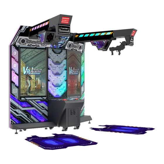
- Page 1 Version 1.02 VR AGENT TWIN-USER MANUAL VR AGENT-TWIN User Manual...
-
Page 2: About This Manual
For further information about the game and repair (including consumables), please contact our company. 3MINDWAVE LIMITED All Rights R eserved. Unauthorized reproduction of this document or any of its contents in any form is strictly forbidden. -
Page 3: Table Of Contents
Table of Contents About This Manual 1. Safety Precautions ........................6 1.1 Warning Stickers ..........................6 1.2 Placing Site ............................7 1.3 Safety Precautions .......................... 8 1.4 Precaution during Play........................9 1.5 Transporting and Moving ......................10 1.6 Installing and Placing ........................11 2. - Page 4 3.4 Operator MENU ..........................44 3.4.1 Game Settings ........................45 3.4.2 Bookkeeping Settings ......................46 3.4.3 Credit Settings ........................47 3.4.4 Input Settings ........................48 3.4.5 Output Settings ........................49 3.4.6 Clock Settings ........................50 3.4.7 Network Settings ......................... 51 3.4.8 Language Settings .......................
- Page 5 6.5 Light-Box Assembly ........................74 6.5.1 Light-Box Wooden Assembly ..................... 75 6.6 Console Assembly ......................... 76 6.6.1 Console Frame Assembly ....................77 6.6.2 Console Panel Assembly ..................... 78 6.6.3 Woofer Assembly ....................... 79 6.6.4 Fan Rear Assembly ......................80 6.6.5 Service Panel Assembly ...................... 81 6.7 L Side Frame Assembly .........................
-
Page 6: Safety Precautions
1. Safety Precautions 1.1 Warning Stickers In order to avoid injury to related people and damage to property, please observe the followings: ▪ The following marks can be used to indicate the magnitudes of risk and damage caused by ignorance or improper operation: Serious Injury: refers to the situations in which medical treatment from a trained medical professional should be sought immediately. -
Page 7: Placing Site
1.2 Placing Site Page 7... -
Page 8: Safety Precautions
1.3 Safety Precautions The owner shall pay attention to the followings when placing, checking and repairing machine to ensure player’s security and avoid damage: Page 8... -
Page 9: Precaution During Play
1.4 Precautions during Play Page 9... -
Page 10: Transporting And Moving
1.5 Transporting and Moving Page 10... -
Page 11: Installing And Placing
1.6 Installing and Placing Pay attention to the following when placing the machine. Page 11... -
Page 12: Product Description
2. Product Description 2.1 Product Specification ▪ Location Indoor Only ▪ Dimension 3500(W) x 2730(D) x 2355(H)mm ▪ Rated Voltage, Frequency AC220V 50Hz /60Hz AC110V 60Hz ▪ Power Consumption 1350W ▪ Weight 642kg ▪ Temperature Range 5~40 °C *110V voltage can be set through the transformer and fuse. Please contact the distributor for details. NOTE: The contents herein described are subject to change without notice. -
Page 13: Cabinet Overview
2.2 Cabinet Overview Page 13... -
Page 14: Parts Name
2.3 Parts Name 2.3.1 – Cabinet Component List Page 14... -
Page 15: Cabinet Led List
2.3.2 – Cabinet LED List Page 15... -
Page 16: Shipment List
2.4 Shipment List ▪ Packing Carton 1 (Main Cabinet Left): 1220 X 830 X 2040MM Page 16... - Page 17 ▪ Packing Carton 2 (Main Cabinet Right): 1220 X 830 X 2040MM Page 17...
- Page 18 ▪ Packing Carton 3 (Console): 630 X 770 X 520MM Page 18...
- Page 19 ▪ Packing Carton 4 (Light Box): 870 X 800 X 450MM Page 19...
- Page 20 ▪ Packing Carton 5 (Crossbeam): 2000 X 280 X 770MM Page 20...
-
Page 21: Packing List
2.5 Packing List Please check the following items after purchasing our product. If any part is missing or damaged, please contact our salesperson. Name Material/Specification Quantity Remarks 3m (1.0m ㎡) (Slanted foot) 1 AC Cable 2 Lexus key 3 Cross flat head screw M4*16 (Black) 4 Hex socket cap screws M4*12 (Chrome) -
Page 22: Install Direction
2.6 Install Direction 2.6.1 – Installation of Cabinet Step 1: Connect the left and right frames 1. Remove 4 Socket head cap screws(M4*35) for liquid crystal door at right frame and right machine door for later use. 2. Remove four 4 Socket head cap screws(M4*35) for liquid crystal door at left frame and left machine door for later use. - Page 23 Page 23...
- Page 24 Step 2: Connect the left and right frames to the main frame 1. Remove 16 Socket head cap screws(M4*12) on the right frame and remove two right frame covers for later use. 2. Remove 16 Socket head cap screws(M4*12) on the left frame and remove two left frame covers for later use.
- Page 25 Step 3: Connect the middle frame to the main frame 1. Connect wires at two places above the middle frame and at the main frame (two persons are required to work together). 2. Lock the middle frame to the main frame via using eight M4 flat head hex screws. Page 25...
- Page 26 Step 4: Connect the left and right pedals with console box and main frame 1. Remove 4 Socket head cap screws(M4*12) the right pedal and remove the cover of right pedal for later use. 2. Remove 4 Socket head cap screws(M4*12) on the left pedal and remove the cover of left pedal for later use.
- Page 27 Step 5: Connection of the fixing seat for gun beam and the main frame 1. Remove 4 Cross combination screws(M4*20) for supporting iron of the fixing seat and remove them for later use. 2. Remove 8 Socket head cap screws(M4*20) on two rear covers of lightbox and remove them for later use.
- Page 28 Page 28...
- Page 29 Step 6: Connect the theme lightbox, theme light board and main frame 1. Use four M4*16 (black-plated) cross large flat head screws to fix the theme lightbox on the fixing seat for gun beam and the main frame (this operation shall be caried outby two persons via cooperation, and two herringbone ladders are required), connect the wire, pay attention to the distinction between left and right.
- Page 30 Step 7: Connect the air cannon to the gun beam 1. Connect the wires between air cannon and the gun beam. 2. Use six M6*16 (black-plated) outer hexagon screws to fix the air cannon on the gun beam (do not clamp the wire). Page 30...
- Page 31 Step 8: Connection of gun beam assembly and the fixing seat for gun beam 1. Put the gun beam assembly slowly into the fixing seat for gun beam (note: clean up wires at the rear to prevent it from being clamped) and fix it on the fixing seat for gun beam with eight M8*40 hex screws (with spring washers and flat washers).
- Page 32 Step 9: Installation of decorative plate for speaker and supporting iron for the fixing seat 1. Use 4 Cross combination screws(M4*20) each to fix two supporting irons for fixing seat on the fixing seat for gun beam respectively 2. Connect the wires between decorative plate for speaker at one side and the fixing seat for gun beam, lock and fix it with six M4*12 (chrome-plated) hex large flat head screws.
- Page 33 Safety Range of Installation Page 33...
-
Page 34: Installation Of Transformer Wiring Switch
2.6.2 – Installation of Transformer Wiring Switch Page 34... -
Page 35: Warranty
2.7 Warranty Page 35... -
Page 36: Game Description And Ao Menu
3. Game Description and AO MENU 3.1 Game Description 3.1.1 GAME FEATURE • Immersive Missions with unique VR aiming Control with Haptic Rumble feedback • Up to 4 players linked play • 5 Exotic Stages with Final Stage to face the BOSS •... -
Page 37: Game Content
3.1.2 GAME CONTENT Scenes There are total of 5 scenes: • 1 - Nightclub • 2 - Tunnel • 3 - Factory • 4 - Warehouse • 5 - BOSS Stage Page 37... -
Page 38: Game Flow
Stages • There are total of 5 stages. Difficulties • There are 3 levels of difficulties: Easy, Normal and Hard Game Modes • 1 PLAYER SOLO • MULTIPLAYER (support link-play up to 4 players at a time) 3.2 Game Flow 3.2.1 Front-End MENU (1) Insert Coin Page Insert coin page will be appeared to ask player to insert coins and start the game. - Page 39 (2) Warning Message A warning screen will appear after game is started. (3) Select Game Mode 1 PLAYER SOLO and MULTIPLAYER (support link-play up to 4 players at a The game has two game modes: time) Page 39...
-
Page 40: In-Game Hud
(4) Loading Screen Learning Tips will be shown in loading screen. 3.2.2 In-Game HUD (5) In-Game HUD Game START Game starts at once right after the loading is finished. Page 40... - Page 41 UI Screen During the game, status of the player will be displayed around the screen. 1 - Game countdown time 5 - Enemy's health 2 - Player’s health 6 - Enemy’s weak point(s) 3 - Number of bullets 7 - Enemy position locator 4 - Countdown enemy attack time Page 41...
-
Page 42: Back-End Menu
3.2.3 Back-End MENU (6): Player Result The game ends when the player completes the stage or has no life remaining or time is up. After the game is over, the performance of all players in the stage will be displayed. Page 42... -
Page 43: Usb Drive Patching
3.3 USB Drive Patching USB Patching Steps: 1. Create a directory named [VRAgentUpdate] in the USB (for example, U:\VRAgentUpdate\), and copy the new game update software to this directory. 2. Turn off the host computer of the VR Agent machine. 3. -
Page 44: Operator Menu
3.4 Operator MENU Arcade Operator 1. Under the game Title Screen, press the [Menu] key of the coin control box to enter the [Arcade Operator], the main arcade operator menu is shown as below. 2. In the main menu screen, use the [LEFT] and [RIGHT] arrow buttons to select a menu item, press the [START] button to enter the sub-menu list. -
Page 45: Game Settings
3.4.1 Game Settings [Game Settings], you can set the following items: 1. Enter Setting Items Setting Content Player Life 1-99 Difficulty 1/2/3 (1 = the easiest) Dynamic Difficulty On/Off Reset Settings Reset Back Back 2. After setting or testing, select [back] in the main menu, settings will be saved automatically. Please press [Service] to exit the operation interface. -
Page 46: Bookkeeping Settings
3.4.2 Bookkeeping Settings [Bookkeeping Settings], you can check the following items: 1. Enter Setting Items Check Content Play Info Total Time On Total Coin In Total Credit In Total Credit Continues Total Service Credit Total Service Credit Continues Total Play Single Player Plays Multi Player Plays Single Player Continue... -
Page 47: Credit Settings
3.4.3 Credit Settings [Credit Settings], you can set the following items: 1. Enter Setting Items Setting Content Credit Count 0-24 Service Credits 0-24 Clear Credits Clear Credit to 0 Entry Type Coin/Card Swipe Credit Settings Free Play/ X Coins X Credit Continue Settings Same as Credit Settings/ X Coins X Credit Reset Settings... -
Page 48: Input Settings
3.4.4 Input Settings [Input Settings], you can set the following items: 1. Enter Setting Items Setting Content Trigger Button On/Off Reload Button On/Off Start Button On/Off Down On/Off Option Cycle / Select On/Off Test / Exit On/Off Back / Service On/Off IO Board Connected/Not Connected... -
Page 49: Output Settings
3.4.5 Output Settings [Output Settings], you can set the following items: 1. Enter Setting Items Setting Content Master Volume Idle/Attract Volume Sound Test Off/Left/Right/Sub Light Test Off/Gun Rack/Gun/ Monitor Side Left/ Monitor Side Right/ Logo Left/ Logo Right Air Cannon Test On/Off Motor Test On/Off... -
Page 50: Clock Settings
3.4.6 Clock Settings [Clock Settings], you can set the following items: 1. Enter Setting Items Setting Content Year Year Month Month Date Date Hour Hour Minute Minute Second Second Apply Apply Back Back PLEASE NOTE: Setting the time or date to the past will require the game to restart. -
Page 51: Network Settings
3.4.7 Network Settings [Network Settings], you can set the following items: 1. Enter Setting Items Setting Content Network Status Linked/Linked [X] Cabs / No Link Group ID 1/2/3/4 Cabinet ID 1/2/3/4 The operator will need to operate the AO button of the cabinet in order to connect to other cabinets (the available cabinet IP(s) will be displayed for connection) and set other group ID(s) and other cabinet ID(s) for the connected cabinets... -
Page 52: Language Settings
3.4.8 Language Settings [Language Settings], you can set the following items: 1. Enter Setting Items Setting Content Language English 简体中文(Simplified Chinese) 繁體中文 (Traditional Chinese) Reset Settings Reset Back Back 2. After setting or testing, select [back] in the main menu, settings will be saved automatically. Please press [Service] to exit the operation interface. -
Page 53: Reset All Settings
3.4.9 Reset All Settings On the "Reset All Settings" page, you can reset all settings to the factory settings. 1. Select [Reset All Settings] and press the [START] button to restore all the settings in the arcade to the default values. -
Page 54: Warnings And Errors
4. Warnings and Errors 4.1 VR Aim Controller Warning • Do not pull the VR Aim Controller. 4.2 PCB Error • I/O Connection Error Page 54... - Page 55 • Cabinet ID Error • VR HMD Connection Error • Gun Connection Error Page 55...
-
Page 56: Maintenance And Service
5. Maintenance and Service Maintenance and Service Even though the machine works normally for a long time, the fault will occur. Therefore, please perform routine check and maintenance concerning the following to ensure a long- term use. Page 56... -
Page 57: Assembly
6. Assembly 6.1 Assembly Tree Diagram Page 57... -
Page 58: General Assembly Diagram
6.2 General Assembly Diagram 6.2.1 Cabinet Assembly Page 58... -
Page 59: L Monitor Frame Assembly
6.3 L Monitor Frame Assembly 6.3 L Monitor Frame Assembly Page 59... -
Page 60: L Wooden Frame Assembly
6.3.1 L Wooden Frame Assembly Page 60... -
Page 61: Monitor Glass Assembly
6.3.2 Monitor Glass Assembly Page 61... -
Page 62: Monitor Assembly
6.3.3 Monitor Assembly Page 62... -
Page 63: Pc Assembly
6.3.4 PC Assembly Page 63... -
Page 64: Pc Door Assembly
6.3.5 PC Door Assembly Page 64... -
Page 65: Monitor Door Assembly
6.3.6 Monitor Door Assembly Page 65... -
Page 66: Transformer Assembly
6.3.7 Transformer Assembly Page 66... -
Page 67: Ac Power Box Assembly
6.3.8 AC Power Box Assembly Page 67... -
Page 68: Beam Assembly
6.4 Beam Assembly 6.4 Beam Assembly Page 68... -
Page 69: Motor Assembly
6.4.1 Motor Assembly Page 69... -
Page 70: Slide Assembly
6.4.2 Slide Assembly Page 70... -
Page 71: Guide Wheel Assembly
6.4.3 Guide Wheel Assembly Page 71... -
Page 72: Disinfection Assembly
6.4.4 Disinfection Assembly Page 72... -
Page 73: Synchronous Pulley Assembly
6.4.5 Synchronous Pulley Assembly Page 73... -
Page 74: Light-Box Assembly
6.5 Light-box Assembly 6.5 Light-box Assembly Page 74... -
Page 75: Light-Box Wooden Assembly
6.5.1 Light-box Wooden Assembly Page 75... -
Page 76: Console Assembly
6.6 Console Assembly 6.6 Console Assembly Page 76... -
Page 77: Console Frame Assembly
6.6.1 Console Frame Assembly Page 77... -
Page 78: Console Panel Assembly
6.6.2 Console Panel Assembly Page 78... -
Page 79: Woofer Assembly
6.6.3 Woofer Assembly Page 79... -
Page 80: Fan Rear Assembly
6.6.4 Fan Rear Assembly Page 80... -
Page 81: Service Panel Assembly
6.6.5 Service Panel Assembly Page 81... -
Page 82: L Side Frame Assembly
6.7 L Side Frame Assembly 6.7 L Side Frame Assembly Page 82... -
Page 83: Middle Frame Assembly
6.8 Middle Frame Assembly 6.8 Middle Frame Assembly Page 83... -
Page 84: R Monitor Frame Assembly
6.9 R Monitor Frame Assembly 6.9 R Monitor Frame Assembly Page 84... -
Page 85: R Wooden Frame Assembly
6.9.1 R Wooden Frame Assembly Page 85... -
Page 86: R Side Frame Assembly
6.10 R Side Frame Assembly 6.10 R Side Frame Assembly Page 86... -
Page 87: Logo Assembly
6.11 LOGO Assembly 6.11 LOGO Assembly Page 87... -
Page 88: L Upper Frame Assembly
6.12 L Upper Frame Assembly 6.12 L Upper Frame Assembly Page 88... -
Page 89: R Upper Frame Assembly
6.13 R Upper Frame Assembly 6.13 R Upper Frame Assembly Page 89... -
Page 90: Gun Assembly
6.14 Gun Assembly 6.14.1 Gun Parts Diagram Page 90... -
Page 91: Gun Parts Diagram
6.14.1 Gun Parts Diagram Gun Parts Table: Page 91... -
Page 92: Gun Wires And Cables
6.14.2 Gun Wires and Cables Page 92... -
Page 93: Printing Pattern
7. Printing Pattern 7.1 Printing Pattern of Cabinet Page 93... -
Page 94: Caution/Warning Labels
7.2 Caution/Warning Labels 7.2.1 Definition of Private Labels (PL) PL – Private Label. A private label product is manufactured by a contract or third-party manufacturer and sold under a retailer’s brand name. Private label brands are exclusive to a retailer, which can help target a specific audience. -
Page 95: Location Of Caution/Warning Labels
7.2.2 Location of Caution/Warning Labels Page 95... -
Page 96: Wiring Diagram
8. Wiring Diagram Wiring Diagram 1-4 Page 96... - Page 97 Page 97...
- Page 98 Page 98...
- Page 99 Page 99...
- Page 100 Page 100...
-
Page 101: After-Sales Service
SPARES AND SERVICE CONTACT INFORMATION -SEGA TOTAL SOLUTIONS- 42 Barwell Business Park Leatherhead Road Chessington Surrey KT9 2NY United Kingdom Contact: +44 (0) 208 391 8060 Option 1 for Spares, Prize, and Sales Option 2 for Technical, Warranty, and Repairs -PLAY IT AMUSEMENTS- 870 Lively Blvd Wood Dale... - Page 102 VR AGENT TWIN User Manual Page 102...
Need help?
Do you have a question about the VR AGENT-TWIN and is the answer not in the manual?
Questions and answers