Table of Contents
Advertisement
Advertisement
Table of Contents

Related Manuals for Rainbow Robotics RB Series


Summary of Contents for Rainbow Robotics RB Series
- Page 1 Ver: v3.2.1...
- Page 2 : 2021 / 02 PDATE...
-
Page 3: Table Of Contents
NDEX Preface ..............................6 Chapter 1. Introduction ........................7 1.1 Rainbow Robotics’ Collaborative Robots ................... 7 1.2 System Configuration ......................... 8 1.3 Robot Arm ............................11 1.4 Control Box ..........................17 1.5 Teaching Pendant Tablet PC (Optional) ................20 1.6 Joint Limit ............................22 1.7 Workspace ............................ - Page 4 3.10 General Purpose Analog I/O Configuration ................... 53 Chapter 4. Get Started ........................55 4.1 Control Box On/Off .......................... 55 4.2 Table Pendant/PC On/Off ........................ 57 Chapter 5. Software Overview ..................... 58 5.1 UI Structure ..........................58 5.2 Startup Screen Display ........................59 5.3 Main Screen Display ........................
- Page 5 8.6 Set-up(Serial) ........................... 279 8.7 Set-up(I/O 1) ..........................280 8.8 Set-up(I/O 2) ..........................287 8.9 Set-up(Inbox) ........................... 289 8.10 Set-up(Interface 1) ....................... 290 8.11 Set-up(Coordinate) ....................... 291 8.12 Set-up(Devices) ........................292 8.13 Set-up(Tool List) ........................293 Chapter 9. Maintenance ....................... 294 9.1 Check List and Period ........................
-
Page 6: Preface
User is solely responsible for any misuse or alteration of the patent rights of this equipment. The information contained in this manual is reliable. The information provided in this manual is the property of Rainbow Robotics Inc. and may not be reproduced in whole or in part without of Rainbow Robotics Inc.’s consent. The information contained in this manual is subject to change without notice. -
Page 7: Chapter 1. Introduction
The RB product line from Rainbow Robotics is a series of collaborative robots. The RB series is designed to be easily accessible and usable to anyone. The RB series is specialized to perform regular, continuous, and repetitive tasks in small and dense human environments across various fields without any additional safety devices. -
Page 8: System Configuration
1.2 S YSTEM ONFIGURATION The system configuration of an RB is illustrated in the figure below. < Stand-type control box system configuration > < Rack-type control box system configuration > Robot Arm: The Robot Arm is an industrial collaborative robot that can be used for the repetition of simple tasks, carrying small objects, or assembling parts. - Page 9 The RB contains system components and accessories as described below. Stand-type control box components <Robot Arm> <Control Box> <Interface / Cables> <User Manual> <Tablet PC> 1 EA Robot Robot Arm 1 EA Control Box Estop/Jog Interface 1 EA System Components Power cable 1 EA Cable between Robot Arm-Control Box...
- Page 10 Rack-type control box components <Robot Arm> <Control Box> <Cable> <User Manual> <Tablet PC> 1 EA Robot Robot Arm 1 EA Control Box 1 EA Emergency switch & cable 1 EA 48V switch & cable System Components 1 EA Power cable 1 EA Cable between Robot Arm-Control Box 1 EA...
-
Page 11: Robot Arm
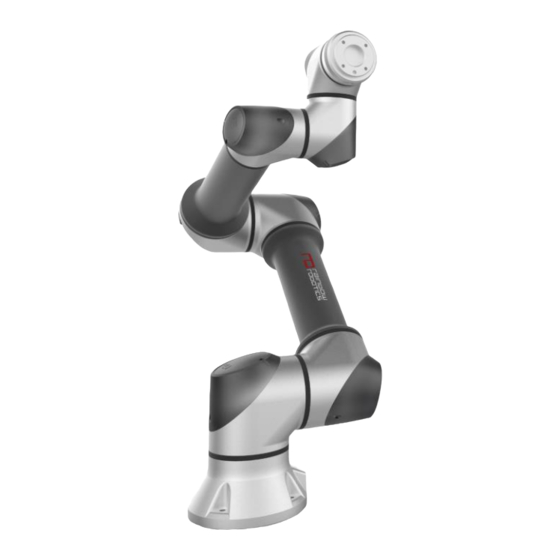
1.3 R OBOT RB Series Joint Description Name ① Base ② Base Joint ③ Shoulder Joint ④ Elbow Joint ⑤ Wrist 1 Joint ⑥ Wrist 2 Joint ⑦ Wrist 3 Joint ⑧ Tool Flange... - Page 12 RB Series Component Description Name Description ① Teaching Button Button for direct-teaching ② Tool Flange Part for mounting tool or gripper ③ Tool I/O I/O ports to control tool or gripper ④ Base Part for mounting the robot arm ⑤...
- Page 13 Dimensions [RB5-850] [RB5-850A1/A2/A3] [RB3-1200] [RB3-1200A1/A2/A3]...
- Page 14 [RB10-1300] [RB10-1300A1/A2/A3]...
- Page 15 Configuration of the embedded Pneumatic-tubing/Electric-line in RB5- 850A#, RB10-1300A#, and RB3-1200A#.
- Page 16 ※ RB5-850A#, RB10-1300A#, RB3-1200A# model's pneumatic lines and wire lines are provided as shown in the following table, please refer to the picture above for use. Model Name Pneumatic Lines Wire Lines RB3-1200A1 4ea(4∅ Pneumatic Tube) None RB3-1200A2 5ea(4∅ Pneumatic Tube) 12 Pin(AWG28, Teflon) RB3-1200A3 None...
-
Page 17: Control Box
1.4 C ONTROL The front and lower/inner sections of the control box are illustrated in the figure shown below. Stand-type control box <Bottom section> <Top section> <Main connector/socket>... - Page 18 Name ① AC Power Socket (AC POWER) ② AC Power Switch (AC SWITCH) ③ Connector for Robot Arm cable (ROBOT) Connector for TEACH PENDANT ④ (EMO/TEACH PENDANT) ⑤ ⑥ Main Switch ⑦ USB/LAN connectors ⑧ I/O ports...
- Page 19 Rack-type control box <Front section> <Back section> Name ① Power switch ② Reset switch ③ 48V switch ④ USB ports ⑤ ⑥ LAN (RJ45) port ⑦ AC Power socket ⑧ Connector for Robot Arm cable ⑨ Connector for Emergency Stop cable ⑩...
-
Page 20: Teaching Pendant Tablet Pc (Optional)
1.5 T PC (O EACHING ENDANT ABLET PTIONAL The teaching pendant/tablet PC is an optional accessory. It MUST be purchased separately. For rack-type control box The teaching pendant/tablet PC is an optional accessory. It MUST be purchased separately. It consists of an Android tablet PC, a protective case, and a neck strap. The section below illustrates the tablet PC as well as further descriptions Name Description... - Page 21 For stand-type control box ※ Purchasing the tablet PC is not required. The App to operate the RB series can be downloaded from Rainbow Robotics’ website. ※ Tablet setup is required for use with RB products. See the Appendix.
-
Page 22: Joint Limit
1.6 J OINT IMIT An RB robot consists of six joints. The axes of rotation and joint limits are illustrated in the following section. Joint Range ° ± 360 ° ± 360 ° ± 165 ° ± 360 ° ± 360 °... -
Page 23: Workspace
1.7 W ORKSPACE The maximum radius is an 850mm workspace for the RB5-850 Series. The maximum radius is 1300mm For the RB10-1300 Series and is 1200mm for the RB3-1200 Series. The area A in the figure below represents the kinematic singular area. This means that any motion programmed in the inertial coordinate system (e.g. -
Page 24: Maximum Load Capacity
1.8 M AXIMUM APACITY The maximum payload of the robot arm depends on the distance between the tool flange and the center of mass of the payload. The maximum payload according to this distance is as follows. -
Page 25: Chapter 2. Safety & Precautions
2. S & P HAPTER AFETY RECAUTIONS 2.1 S AFETY NDICATIONS The following safety notices are used in this manual. Danger Failure to follow instructions marked with this symbol may result in severe harm, which could result in serious injury or death. Warning Failure to follow the instructions with this symbol may result in an accident, which could result in serious injury to the user. -
Page 26: General Safety Warning & Precautions
4) Never operate a broken or a faulty robot. 5) If a fatal error occurs in the software, immediately hit the emergency switch to stop the robot, then contact your supplier or Rainbow Robotics. 6) Check that the robot installation angle, tool setting, safety setting, etc. are entered correctly. - Page 27 10) Please do not modify the robot without the support of Rainbow Robotics. Rainbow Robotics (hereinafter "the manufacturer") assumes no responsibility for any problems caused by user's modification or modification of the product. 11) Both the robot arm and the control box generate heat when used for a long time.
- Page 28 Caution Caution: 1) When using with a machine or another robot that can damage the robot arm, it is recommended to test all functions separately before use. The manufacturer is not responsible for any programming errors, damage to the RB, or damage to other machines due to robot malfunctions. 2) Do not expose the robot to strong magnetic fields as the robot may be damaged.
-
Page 29: Usage & Functionality
2.3 U & F SAGE UNCTIONALITY The robot arm is intended to be used for transferring and assembling objects by utilizing tools and should only be operated in the environment specified in the description. It is possible to work without a physical protective barrier. However, a safety mechanism should be used after performing the risk evaluation for the whole system. -
Page 30: Potential Safety Issues
2.4 P OTENTIAL AFETY SSUES Additional protective measures must be taken if the final system is deemed unsafe or unable to adequately reduce risk. Users should consider the following potential risks: Injury (stenosis), which may occur when a finger is caught between the gears, etc., ... -
Page 31: Liability Limitations
2.5 L IABILITY IMITATIONS This manual does not cover all peripherals that affect safety. The system installer must comply with safety requirements in accordance with national safety regulations and the laws of the country where the robot arm is installed. The robotic arm consists of an end-coupled system of peripherals. -
Page 32: Shipping & Transportation
2.6 S & T HIPPING RANSPORTATION At least two people are required for transportation. Any damages to the robot incurred during shipment or transportation are excluded from the warranty. Warning Warning: 1) Be careful not to damage the product during transportation. Damages incurred during transportation will void the warranty. -
Page 33: Emergency Stop
2.7 E MERGENCY The emergency stop button can be used to forcefully stop the robot arm if there is an emergency. By pressing the emergency stop button, the user will stop commands sent from the robot control box and terminate any motion. The section below describes how the emergency stop button for stand-type control box works. - Page 34 And the section below describes how the emergency stop button for rack-type control box works. Emergency Stop Users can stop the robot arm immediately by pressing the EMERGENCY STOP button on the EMERGENCY STOP switch. Re-Activating from Emergency Stop Turning the button clockwise on the emergency stop switch releases the emergency stop button.
-
Page 35: User Safety
2.8 U AFETY For the user’s safety, please note the following: Powerless robot operation In case of an emergency, or in any situation without power, the user can move the robot arm by forcing the joints into a different configuration (forced back driving). To perform forced back driving, the user must push or pull the robot arm firmly. -
Page 36: Safety Controller
2.9 S AFETY ONTROLLER The Safety Control System of Rainbow Robotics’ RB5-850 Series, RB10-1300 Series, RB3-1200 Series follows ISO 13849-1 Cat4. PLe (OMRON G9SE-201) and the design specification is ISO 13849-1 Cat3. PLd. -
Page 37: Risk Assessment
2.10 R SSESSMENT A risk assessment is important when creating a system that uses robots, including the RB. The safety factors to be considered when operating the robot depend on the configuration and integration of the robot arm into the whole system. As such, the robot alone cannot be used for risk assessment. -
Page 38: Chapter 3. Installation
3. I HAPTER NSTALLATION 3.1 I NSTALLATION RECAUTION Robot installers must install and operate the robots in accordance with the guidelines of ISO 12100 and ISO 10218-2, and installers must comply with the relevant requirements of international standards such as ISO / TS 15066 and national laws. The manufacturer is not responsible for any accidents caused by risks that do not comply with the relevant requirements provided by international standards, risks that do not comply with the relevant requirements provided by national laws and... -
Page 39: Installation Location
3.2 I NSTALLATION OCATION The manufacturer recommends the following conditions are met for the installation location. Building with seismic design No leakage No flammable or explosive material Constant temperature and humidity Limited dust inflow Caution Caution: 1) If the system is not installed in a location that matches the recommendations, the performance and lifespan of the robot may be reduced. -
Page 40: Examples Of Installation
3.3 E XAMPLES OF NSTALLATION The robot arm can be installed on a horizontal surface (e.g. a table), a wall, the ceiling, or any other angle. However, the user must set the angle of installation in the system-setup when installing on a surface that is not a horizontal surface. <Installation on the horizontal surface>... -
Page 41: Mounting The Robot
3.4 M OUNTING THE OBOT It is recommended to use four M8 30mm bolts for robot arm installation. Warning Warning: 1) When attaching the robot, fix it firmly so that the bolts do not come loose. 2) Install the robot on a sturdy surface that can withstand the combined weight of the robot and the load generated by the robot. -
Page 42: Tool Connection
3.5 T ONNECTION Use four M6 bolts to secure the tool to the tool flange. Tools and M6 bolts are not included in the product. The connection methods may be different between tools. Please contact the tool manufacturer for further details. ... - Page 43 The tool I/O has a 12-pin connector. The port specifications in the tool flange are as follows. Port Layout Pin num Signal Digital Output A Digital Output B 0/12/24 VCC Ground Digital Input A Digital Input B Tool I/O Analog Input A Analog Input B RS485+...
- Page 44 The tool connector uses NPN (‘sinking’) for the digital output. When the digital output is enabled, the corresponding port is connected to GND (ground). When the output is deactivated, the corresponding port becomes ‘open’ (open-collector / open-drain). The electrical specifications are as follows.
- Page 45 The tool analog input measures the voltage in a non-differential manner. The measurement categories are as follows. Nominal Unit Input Voltage Resolution The figure below shows how to connect an analog sensor with non- differential voltage output characteristics to the tool flange. ...
-
Page 46: Cable Connection
3.6 C ABLE ONNECTION The cable connection for stand-type control box describes as follows. Connecting the robot arm to the robot control box using the robot arm cable. Please connect the female connector to the robot arm and the male connector to the control box. - Page 47 The cable connection for stand-type control box describes as follows. Connecting the robot arm to the robot control box using the robot arm cable. Please connect the female connector to the robot arm and the male connector to the control box. Please check whether pins in the connector are bent or not.
-
Page 48: Robot Control Box I/O Overview
3.7 R I/O O OBOT ONTROL VERVIEW To connect other external devices to the robot control box, please connect the I/O from the control box to the corresponding device. The I/O of the control box is very flexible, so it can be used to connect with various equipment such as relays, PLCs, and emergency stop buttons. -
Page 49: Safety Input Configuration
3.8 S AFETY NPUT ONFIGURATION For the safety of users, all safety-related I/O must be configured with multiple backups. Safety devices and equipment must be installed in accordance with the instructions in Chapter 2 Safety and Chapter 3 Installation. Danger Danger: 1) Never connect a safety signal to a PLC other than a safety PLC. - Page 50 Safety protection stop and automatic restart An example of a safety protection device would be a door switch that stops the robot when the door is opened. The figure shows how to configure these features: Enabling Device Input (Option) Connect the active device input interface using the 3-position switch.
-
Page 51: General Purpose Digital I/O Configuration
3.9 G I/O C ENERAL URPOSE IGITAL ONFIGURATION All Digital I/O can be used as general purpose digital I/O. To use other external equipment with the robot, connect the I/O from the robot control box with the corresponding equipment. The universal digital I/O can be used to configure devices such as relays or PLC systems. - Page 52 Communication with other system or PLC If another other system provides PNP and uses a common ground, the digital I/O can be configured to communicate with the other system. Its connection is shown in the figure below. Warning Warning: For the details in the technical specification and wire connection, please refer to Appendix D.
-
Page 53: General Purpose Analog I/O Configuration
3.10 G I/O C ENERAL URPOSE NALOG ONFIGURATION The following methods are recommended for high reliability. Use analog GND closest to I/O. Equipment and control box use the same GND. Analog I/O is not isolated from the robot control box. ... - Page 54 Analog input The figure shown below illustrates a simple connection to an analog sensor. The output value of the analog sensor can be used by the control box as analog input. LCD Status Display 1. Display Box (1): Displays information about system status : Please Wait (the main PC in the control box is booting up) : Normal Operation (the main PC in the control box is ready) 2.
-
Page 55: Chapter 4. Get Started
4. G HAPTER TARTED 4.1 C ONTROL Procedure for turning control box On/Off is as follows Stand-type control box On/Off Press the AC power switch at the bottom of the control box to apply AC power. Press the main power switch at the top of the control box to turn on the main power. "Please Wait"... - Page 56 Rack-type control box On/Off Turn the power switch at the bottom of the control box to connect the power to the control box. "Please Wait" is displayed in the LCD screen of the control box. This indicates that the control box is being booted. When the control box is changed to the enabled state, the LCD message is displayed as "Normal Operation".
- Page 57 4.2 T /PC O ABLE ENDANT If the user uses the teaching pendant provided by Rainbow Robotics, the teaching pendant and cover are provided. To turn on the teaching pendant, press the power button on the top left corner. ...
-
Page 58: Chapter 5. Software Overview
5. S HAPTER OFTWARE VERVIEW 5.1 UI S TRUCTURE The UI (User Interface) program is divided into three screens as follows. Each section allows the user to enter necessary steps. -
Page 59: Startup Screen Display
5.2 S TARTUP CREEN ISPLAY Intro The below image shows the start screen. The start screen will occur while the application is loading its processes. Login (Factory-Default login password: 0000) To set up the password or to enable automatic login, please go to the "Setup-System-Password"... -
Page 60: Main Screen Display
5.3 M CREEN ISPLAY The UI has three main menus. Make : for programming robot motion and tasks. Play : for running motion and tasks pre-programmed in the Make menu. Setup : for setting up parameters. In the main screen, users can create programs for the robot (Make), move the robot (Play), or set settings (Setup) through each relevant menu. -
Page 61: Make
5.4 M Make The Make screen is the interactive menu to program the robot. Programming the collaborative robot will also be referred to as “teaching.” Teaching the robot requires the use of the icons at the top of the screen. Moving the robot requires the use of icons at the right. -
Page 62: Play
5.5 P Play The Play screen allows the user to load and run a teaching program. The Play screen only allows for physical movement of the robot (unlike Make, which allows for simulation). A program loaded into the Play screen will repeat the number of times specified in Setup-Interface. -
Page 63: Setup
5.6 S ETUP Setup The Setup screen allows the user to see/change the robot’s default values, such as sensitivity for collision detection, orientation of the robot installation, range of workspace, tool settings, system log, I/O, coordinate system, etc. ※ Please refer to Chapter 8 for more details about Setup. -
Page 64: Chapter 6. Programming Guide
6. P HAPTER ROGRAMMING UIDE 6.1 I CONS AND CTION CREEN Description of components in Make screen display Description ① Show the program list in tree form. Shows the angle of each joint of the robot arm and the Cartesian coordinate position ②... - Page 65 ※ Teaching: programming RB’s motion by means of moving the robot by hand ※ TCP (Tool Center Point): The point defined for the tool center point within the robot’s base coordinate system. It may also be the origin of the end-effector. <Basic View Mode>...
- Page 66 <Program-only Mode>...
- Page 67 Description of icons used in teaching (Upper part in Make page) ※ A detailed description of each function is explained in later chapter Icon Description This icon is used to set motion property of the robot. The core algorithms for seven types of motion properties are pre-programmed.
- Page 68 This icon is used to create another type of conditional statement. For the Switch statement, a user defines each case. This icon is used to repeat a specific section in the motion program. A user can set a specific number of times to repeat. A user can also repeat indefinitely until a condition becomes false, or repeat indefinitely until a condition becomes true.
- Page 69 This icon is used to run a specific command or program only for one time at the beginning of a program. This icon allows a user to run a command or program in parallel to main program. Note that motion commands cannot be used in the thread. This icon generates a message pop-up during operation.
- Page 70 This icon is used to send data to the port located in the Tool flange or Control Box via RS485/RS232. Please refer to Setup-serial for protocols. This icon is used for socket communication. A maximum of five connections are allowed. This is for ModBus Client function.
- Page 71 PWM (Pulse Width Modulation) output function. Input the frequency and duty ratio of the PWM pulse to send PWM signal through digital output port. This function allows a user to define repetitive behavior. By defining information about the space in which to perform the repetitive actions, as well as defining the repetitive actions to be performed at each location, the robot will perform the same action...
- Page 72 The TCP settings feature is the ability to temporarily change TCP values by recalling pre- saved TCP values during program execution. User can save TCP values in advance from the Tool List on the Setup page. Manual direct teaching is a feature that allows user to pause and use direct - teaching while the program is running.
- Page 73 Icon description for editing (Left side in Make screen) Icon Description It recalls the currently open file. ※If you press Reload button without pressing Save button, you will be able to blow up the last saved file, so be careful. It reverses your last action.
- Page 74 It can paste the copied or cut command into the selected location. It can cut the selected command. This command can be pasted to a different location. It can delete the selected command. It can change edit mode to zoom mode.
- Page 75 Jog and other utilities (Right side of Make screen) 아이콘 설명 It can move TCP’s position relative to a global coordinate system fixed to the base. It can move the position of TCP based on the local coordinate system (tool coordinate system) fixed to TCP.
- Page 76 System function button This icon is used to move to home screen & another page. It is located in the top left. This icon is used to power off the UI. When the tablet PC is connected to the robot, the robot will also be turned off.
-
Page 77: Create Teaching Environment
6.2 C REATE EACHING NVIRONMENT Robot teaching (programming) is available only in the Make screen. Please open the Make screen from the Play or Setup screen via the button located at the top of the UI. It is also possible to move to the Make screen from the Home screen. ... - Page 78 The figure below shows a display when the tablet PC and control box are being connected. ‘Network Connecting’ lights yellow when the tablet PC is trying to connect to the control box. ‘Network Connected’ becomes blue when the table PC and control box are connected properly.
- Page 79 After ‘Network Connected’, press the ‘Control’ button to activate the robot control system. ‘Control’ button: Will initialize the robot arm for operation. ● During initialization, the mechanical joint brake is released. Unlocking the joints will generate a clicking sound. All lights become blue when the robot is ready. ※...
- Page 80 Create New Project Press the ‘New’ button at the bottom of the screen to create a new project and can give the file a name. The default name of a new project is ‘default’. Please type a name for the new project and press the ‘Save’...
-
Page 81: Teaching (Programming)
6.3 T EACHING ROGRAMMING Ways to Move the Robot Direct-Teaching: When a user manually rotates each joint to change the pose of the robot. Jogging: When a user uses the jog buttons in the UI to move the robot. ... - Page 82 Jogging There are four modes of jogging. Mode 1: TCP Movement in the Cartesian coordinate system with respect to the base (global) frame. Mode 2: TCP Movement in the Cartesian coordinate system with respect to the tool (local) frame. ...
- Page 83 There two ways to control jogging: Smooth: Use for continuous motion of the robot. When the ‘+’ or the ‘-‘ button is pressed and held, the robot moves continuously until the button is released. Tick: Use for discontinuous motion of the robot. The robot will move a specific amount as defined by the user each button click.
- Page 84 <Jog Mode 1: TCP jog w/ Global coordinate> < Jog Mode 2: TCP jog w/ Local coordinate>...
- Page 85 < Jog Mode 3: TCP jog w/ User coordinate> < Jog Mode 4: Joint jog w/ joint coordinates>...
- Page 86 Real Robot and Simulation Modes Two Modes are available for testing the robot’s movement. Simulation Mode: ● Allows the user to virtually move the robot arm on the UI screen without moving the actual robot. It is recommended to run simulation mode first for safety reasons before teaching a new motion.
- Page 87 Teaching Robot Movement The basic robot teaching functions are Move and Point. Both icons are on the top bar when using the Make screen. Move: Defines motion property. Generates a movement command for the robot arm. Requires points to be defined. ...
- Page 88 Move Function Move sets the robot arm's motion properties. The two primary types of movements are Joint and Linear. These types are further broken down into commands, as shown in the figure above. ■ Joint Movement Commands The Joint Movement Commands generate movement by setting the angular value of each individual joint (in degrees).
- Page 89 ■ Linear Movement Commands The Linear Movement Commands generate movement by setting the position of the TCP in the Cartesian coordinate system. These commands use Cartesian coordinates (x,y,z coordinate values and rotations) as the target values for the movement. ▷ MoveL (Move Linear) : Moves the TCP linearly (using x, y, and z) from the current position to the position contained within the target Point (in mm).
- Page 90 ▷ MoveJL (Move J with Linear Input) : Like MoveL, the Cartesian value of the target point is used as input. However, instead of going straight to the point, it uses MoveJ's method. When the Cartesian coordinate system input is received, it is converted into the target joint angle through inverse kinematics and inputted again to MoveJ.
- Page 91 Difference between MoveJ and MoveL MoveJ does not consider the movement trajectory of the terminal (TCP). It is an operation that only uses the joint angle information of the starting point and the joint angle of the target point. The driving speed of other joints are adjusted to the joints that require the most driving time.
- Page 92 Difference between MoveL, MoveLB/PB, and MoveITPL MoveL moves in a straight, linear path between the start and destination points. The arm will arrive at each sequential arrival Point, stop, and then continue to the next Point. MoveLB/PB starts at the initial Point, uses each intermediate Point as a waypoint, then stops at the final Point.
- Page 93 Warning Warning: 1) The five linear motion commands (MoveL, MoveLB, MovePB, MoveJL, MoveITPL) move the robot using inverse kinematics calculations. Therefore, movement may be limited in singularity positions where inverse kinematics calculations are not possible. 2) Certain joints may move faster or be restricted in motion while in the dead zone of the robot.
- Page 94 Changing Move Function Commands When the Move Function is used for the first time in a program, the program tree will be created as shown below. By default, the Move function is set to MoveJ. Click MoveJ in order to change the Move command type. A popup will appear as shown below.
- Page 95 An example of a teaching program is shown below. MoveJ , MoveJB The arm moves to the joint angle configuration contained within each Point. Each angle value is relative to the base position. ※ Since the robot arm consists of six joints, the MoveJ and MoveJB functions will move all six joints based on the configuration contained within each Point.
- Page 96 Point Function Motion property 1 Destination 2 Destination As explained earlier, the Point function is a sub-function of the Move function. Move specifies the properties of the motion, whereas Point is responsible for setting the target position. Note: In the Point function, the target value will vary depending on the command type of the Move function.
- Page 97 When a user taps on a Point in the program tree, the Point function popup window will appear. The window contains the following fields: Each area is described in the table below.
- Page 98 Section Description Sets the name of the point (not required). ① After setting the name, the location information of the point can be used as a variable later. Allows a user to select the setting type of the point function. The Joint Move has three setting options.
- Page 99 ※ An example using the Get function (Section 4) is shown below. 1. Use the jog / direct teach function to move to the desired posture / position 2. Get current posture / location information by pressing Get button...
- Page 100 3. Save after confirming reflection...
- Page 101 ※ An example using the Finish at/Stopping time option (Section 6) is shown below. ■ When not using the Finish at function (If left blank) End of motion after arrival to original set target point, execute next command ■ When using the Finish at function (When entering a specific conditional expression) Even if the target point is not reached, the operation is terminated when the Finish at condition occurs and the next command is executed.
- Page 102 The following setting options exist for each type of move function. Joint Move Type’s sub Point >Sets the Points for MoveJ by using fixed, user defined joint angles Absolute >Requires the user to set the desired posture/joint angle configuration through the Get function. >Sets the Points for MoveJ by using one of several methods.
- Page 103 Linear Move Type’s sub Point >Sets the Points for MoveL by using fixed, user defined Cartesian coordinate values >After moving the robot's TCP, Cartesian coordinate Absolute values through the Get function can be set >Note: The default Cartesian coordinate system for the Absolute Point Type is the base coordinate system of the robot arm (manufacturer's default coordinate system).
- Page 104 The figure below shows each different type of Point as it displays in the UI. ▶ Joint Type - Absolute point ① Absolute Option point ② The robot's posture/angle value is saved through Get button.
- Page 105 ▶ Joint Type – Variable point ① Variable Option point. ② Allows the user to enter the joint angle for the target posture or enter the parameterized information as an equation.
- Page 106 ▶ Joint Type – Relative point ① Relative Option point ② Allows the user to enter how much each joint should move relative to the previous joint angle. All angles are in degrees. In addition, it allows the user to enter parameterized information or formulas.
- Page 107 ▶ Linear Type - Absolute point ① Absolute Option point ② Allows the user to save a posture/position by using the Get/Save button. The reference coordinate system of the Cartesian coordinate system value is the robot base coordinate system.
- Page 108 ▶ Linear Type – Variable point ① Variable Option point ② Allows the user to enter the target Cartesian coordinate values. The user can also enter parameterized information as formulas. The reference coordinate system of the set Cartesian coordinate values is the base coordinate system of the robot arm.
- Page 109 ▶ Linear Type – Relative point ① Relative Option point ② Requires the user to enter the distance/angle offset relative to the reference point. Also allows users to enter variable information. ③ Allows a user to select a user defined point from which to move. The default value is PT_LAST_TCP, which indicates the last arrival point.
- Page 110 ▶ Linear Type – User Coordinate point ① User Coordinate Option point. ② The User Coordinate Option is similar to Variable, but it allows the user to set the target point based on a previously defined user coordinate system. Users can also enter variable information.
- Page 111 Warning Warning: 1) A user coordinate system can be set through the Coordinate menu in the Setup screen or by using the Setting function in the Make screen. 2) Up to 3 user coordinate systems can be set and used. 3) The factory default user coordinate system is the same coordinate system as the robot base coordinate system.
- Page 112 Changing Movement Properties The following conditions apply when changing the action properties (type of move) of a configured action. Switching in the same series can be done without any restrictions. Switching to another types (Move Joint types-> Move Linear types / Move Linear types->...
- Page 113 Example of Basic Program Creation The following is an example of creating and running a simple program based on the above Move and Point functions. [Step 1] Create a new project. In this case, the name of the project is ‘test’. [Step 2] Click the Move function to add a Move command to the program tree.
- Page 114 [Step 3] Using the Jog button, move the robot to its intended position. In this example, the robot was moved to the following joint angle: [Base:0’, Shoulder:0’, Elbow:90’, Wrist1:-90’, Wrist2:90’, Wrist3:0’]. Click on a Point in the program tree to display the Point setting popup window as shown below.
- Page 115 [Step 5] After saving the point, the UI will look as follows. [Step 6] Repeat steps 1 - 4 several times to teach the robot the desired motion. Our completed example program will look like the following.
- Page 116 [Step 7] After the program is finished, run it on the work screen by pressing the play (▷) button. To run the movements using the simulation arm, use the Simulation mode. To run the movements using the real robot arm, use Real Robot mode.
- Page 117 [Step 8] After receiving the popup in Step 7, the program is ready to run. Click the play button at the bottom again to run the program. The image below shows the program running. Warning Warning: 1) The Point that the robot is current moving towards will be displayed as yellow in the program tree.
- Page 118 Initial Movement Position The initial position can be modified in the Begin section of the program. Before running a program that contains movement, the robot must return to the initial position. The initial position can be changed by the following way. 1.
- Page 119 Collision detection during operation The RB Series has two built-in collision detection functions: - External Collision Detection (Environment-Collision Detection) - Internal Collision Detection (Self-Collision Detection) < External Collision > < Internal Collision > ● External Collision (Environment Collision Detection)
- Page 120 To continue, choose one of the two options: Resume: Checks the status and continues robot operation ● Halt: Exits the program ● Alternatively, tap (hit) on the robot arm twice to continue the operation. This will perform the same function as the Resume button.
- Page 121 ● Internal Collision Detection - Occurs when the robot predicts that it will collide with itself. - If the robot extends beyond the preset Workspace limits, it will stop by itself. The setup for the surrounding environment area is done in the Setup screen.
- Page 122 The image below shows a situation where the robot is about to leave the user-defined Workspace. Just before leaving the Workspace, the robot will stop, prompting the UI to display a warning in red. The image below shows a situation where the virtual collision box set up by the user detects / predicts a collision.
-
Page 123: Teaching Icons And Description
6.4 T EACHING CONS AND ESCRIPTION In the previous section 6.3, only the basic teaching functions (Move and Point functions) are described. This section is dedicated to the other teaching functions. ■ Circle Function : The Circle Function provides a movement method for circular motion. There are two Circle methods: Three Point and Axis/Center. - Page 124 Constant: Maintains the initial TCP orientation (Rx, Ry, and Rz) of the TCP through the movements. Intended: The TCP rotation set by the user is followed. Radial: Rotates the TCP orientation with respect to the center point of rotation. Smooth: The turn changes immediately from the start point to the destination point.
- Page 125 Three Point Circle Type The Three Point Circle method draws an arc connecting three points: the starting point, the intermediate waypoint, and the arrival point. ① Circular Motion type selection (3-point setting type) ② Point type (Absolute / Variable / Relative / UserCoord.) ③...
- Page 126 Axis/Center Circle Type Set the center point for the circular motion, the axis of rotation, and the angle to rotate. ① Circular motion selection (axis / center setting type) ② Point type (Absolute / Variable / Relative / UserCoord.) ③ Orientation option (Constant / Radial / Intended / Smooth) ④...
- Page 127 ■ Wait Function : Waits for either a specified condition or a specific amount of time. There are three modes: 1) Wait for a specified amount of time 2) Wait while a condition is true. 3) Wait until the condition evaluates to true. 1) Time Condition Ex) waits for specified amount of time (i.e.
- Page 128 2) Holding Condition Ex) if the condition is true, the function waits indefinitely...
- Page 129 3) Exit Condition Ex) If the condition is true, the process exits the wait function and then executes the next task.
- Page 130 ■ If Function : The If Function allows the users to insert a conditional ‘if’ statement. Depending on the conditions, branches can be set up so that the robot can perform different commands. Users can set the If / else if / else statement. After adding the If function to the program tree and clicking the added If function, the following popup window appears.
- Page 131 ■ Switch Function : Switch statement. Depending on the conditions, branches can be set up so that the robot can perform different commands. Switch / case statements are available. The following popup window appears by clicking the added switch function in the program tree.
- Page 132 ■ Repeat Function : Repeats the nested program by the specified condition. There are three modes – these modes look similar to those within the Wait function: 1) repeat a specified number of times. Note: if a user sets this value to 0, it will repeat indefinitely 2) repeat while the specified condition is true 3) repeat while the specified condition is not true.
- Page 133 2) Holding Condition Ex) While ANALOG_IN_0 and DIGITAL_IN_1 both evaluate to 1, the subprogram will repeat. The subprogram will continue to repeat until at least one of the two values changes.
- Page 134 3) Exit Condition Ex) The subprogram will repeat until both ANALOG_IN_0 and DIGITAL_IN_1 evaluate to 1. The subprogram will continue to repeat until both values become 1.
- Page 135 ■ Break Function : Forcibly terminates a Repeat function. Even if the Repeat condition determines that the subprogram should continue, the Break function can be used to escape the loop. It can only be used as a subitem of the Repeat function – it cannot affect any other part of the program.
- Page 136 ■ Halt Function : Terminates the program. In the example below, the program will check the If function and call the Halt function if the condition is true. If the condition is true, the program will terminate and will not execute the next commands. Warning Warning: 1) When the Halt function is executed, the main program will terminate –...
- Page 137 ■ Assign Function : Declare and designate the value of a variable. Variables can be changed through the program to allow for greater flexibility with conditionals. A variable can be one of the 4 following types: Variable Type: Saves a single numerical (float) variable. ●...
- Page 138 If multiple declarations are made, the program tree will show how many variables of each type were declared. An example popup window of the Assign function is shown below. Note, the below window shows 4 declarations. Each part of the popup encircled in green dotted lines are explained below: 1) Declares the type of variable (Variable, Array, Point, String).
- Page 139 ■ Script Function : Allows the user to write custom scripts. These scripts allow for custom operations / calculations. The Script Function also allows for functions such as variable substitution and assignment. Add the script function to the program tree and click the added script function. The following popup window will appear.
- Page 140 The following example is a program that uses the Repeat function to repeat once every second. After each second, the Script function increases the variable called counter by 1. This will repeat indefinitely, as the loop is set to continue an infinite number of times.
- Page 141 Warning Warning: 1) The script function is an area where the user can freely write and execute a script. 2) If the users write a script that doesn't match the syntax, the program may malfunction or stop. Be mindful and use the proper syntax when using this feature.
- Page 142 ■ Text Function : The Text Function allows users to make notes/comments in the program list tree. The text function is displayed as green text in the program tree and does not affect the functionality of the program. Click the Text icon to add it to the Program Tree.
- Page 143 ■ Folder Function : The Folder function helps to organize commands and manage them as modules. Each Folder can contain commands as sub-items, helping with the flow of the program. Each folder can then be renamed to help provide details to the flow of the program.
- Page 144 Like the Text function, it does not affect the function of the program. This function only helps to manage the flow of the program by allowing for module creation.
- Page 145 ■ Sub.P(Sub Program) Function : Allows users to insert other program files into the current project. These other program files are made in advance and accessed through the file explorer window. Clicking the Sub.P icon opens the file explorer window as shown below. Through the file explorer window, a user can view other projects created on the tablet PC.
- Page 146 In the above example, a subprogram named igtest has been inserted into this project. To see the contents of the subprogram, expand the program tree viewer (shown below in the green dotted lines) and click on the loaded subprogram. The current project is displayed on the left side, and the loaded project contents are displayed on the right side.
- Page 147 A subprogram is executed sequentially along with other programs. If other commands are placed after a subprogram, they will be executed after the subprogram finishes. Warning Warning: 1) The contents of a subprogram called by the Sub.P function can be seen by the user, but they cannot be modified.
- Page 148 ■ Pre.P(Pre Program) Function : The Pre-Program function is a dedicated Folder placed at the beginning of the The Pre-Program folder will execute its contents only once. program. ● Pre-Program will not have an effect on a program in Make mode, since the program will exit when it finishes executing.
- Page 149 The figure below shows the program instruction execution flow when the Pre.P function is used. <Run in Make> <Run in Play> In the Make screen, commands between Begin and End are executed in sequence, regardless of the use of the Pre.P Function. In the Play screen, the program repeats between Begin and End, but the commands contained within the Pre-Program Folder is executed only once.
- Page 150 The figure below shows the Pre.P (Pre-Program) Function used in an actual project. The Pre.P function must be directly after the Begin line, as it runs before the rest of the program. Users cannot copy the Pre.P Folder and paste it elsewhere.
- Page 151 ■ Thread Function : Will create a separate program tree called “Thread.” This program will run in parallel (at the same time) with the main program. However, the thread program tree is limited to using functions that do NOT control robot operation. In other words, the user cannot put a Move, Point, or Circle function in the thread program tree.
- Page 152 The figure below is an example of how the Thread function can be inserted into an actual project. In the example below, two threads are inserted. Warning Warning: 1) For the stability of the program, the use of threads is not recommended within any program called by Sub.P.
- Page 153 ■ Alarm Function : Places a popup message within the flow of the program. The message will disrupt the execution of the program, prompting user confirmation to continue or stop the program. After clicking the Alarm icon, an Alarm will be placed within the program tree. Click the new Alarm to display the setting window as shown below.
- Page 154 To better control the flow of the program, the user can either Resume or Halt the program’s execution from the pop-up. Resume: Continue to the next command ● Halt: Terminate the program ● Pressing the Resume button in the pop-up window will resume the program, whereas pressing the Halt button will stop program at this point.
- Page 155 ■ Debug Function : Function for debugging internal values. Users can make a pop-up display the value of a variable or internal parameter, similar to an Alarm. Debugging is for observing internal variables. It is mainly used to check the value of variables used in the program during program teaching / development.
- Page 156 Add a Debug Function below it. Set the variables in the Debug window to observe the two previously declared variables as shown below.
- Page 157 Once the setting is complete, run the program (the tablet PC and the control box must be connected before execution), and the following pop-up window will appear when the Debug command is executed. The pop-up will allow the user to observe the specified variable values.
- Page 158 ■ Set Function : The Set function allows users to temporarily change parameter settings, regardless of the default values contained within the Setup menu. While the settings in the Setup menu are applied as defaults to all projects, the Set function allows users to temporarily override these parameters.
- Page 159 Disable Box D.out XYZ Projection Orientation Align User Coordinate Config XYZ Shift XYZ Shift2 Vibration sensor Digital Input Simulation Program Flow Control High acceleration Mode Motion Time Constraints High Sensitivity Coll.Detect ...
- Page 160 Set Function: Time Starts the timer and sets the initial value. Starting with the value entered, the value of the timer increases. Set Function: Collision Threshold Change Temporarily sets the collision detection sensitivity. The lower the value, the more sensitive the robot is to collision. This has the same functionality as the Collision Threshold option within the Setup Menu.
- Page 161 Set Function: Tool Payload Temporarily set the tool's weight and center of gravity. This has the same functionality as the Payload option within the Setup Menu. Set Function: Linear Move Offset Gives a slight offset relative to the base coordinate system. This function allows users to temporarily set an offset of up to 20 mm.
- Page 162 Allows the user to enable the Inbox Checking feature. The Inbox Checking feature checks whether a certain part of the robot is in a predefined area (either in the Setup screen or the using the Set function). The parts of the robot that can be checked are as follows.
- Page 163 Is the center of the tool flange inside the specified area? ● Is the TCP inside the specified area? ● Is any part of the gripper (tool box) in the specified area? ● All the above ● The size and position of the box can be set in the Inbox screen using Setup mode (or through the Set function).
- Page 164 Set Function: TCP Position Temporarily set a relative offset of the tool's TCP position. Note: This will change the X, Y, and Z used for Global TCP calculations. It has the same functionality as the End Effector menu in Setup-Tool. Set Function: Tool Collision Box Temporarily set the size and position of a virtual box surrounding the gripper for self-collision prevention.
- Page 165 Set Function: Global Workspace Temporarily set the limits of the workspace for collision prevention. It has the same functionality as the Workspace Limits menu in Setup-Cobot. Set Function: Inbox Size Temporarily set the position and size of the Inbox. It has the same functionality as the Inbox settings in Setup-Inbox.
- Page 166 Set Function: Collision Detection On/Off Temporarily sets the use of external collision detection mode. It has the same functionality as the Enable Collision box in Setup-Cobot. Set Function: Speed Override (speed multiplier) Allows the user to temporarily to change the base scaled speed used by the Move and Point functions.
- Page 167 In the example above, the base speed for Move J is overwritten to be 1.5 times the normal speed, whereas the base speed for Move L is overwritten to be 0.71 times the normal speed. Set Function: Acceleration Override (acceleration multiplier) Allows the user to temporarily to change the base scaled acceleration used by the Move and Point functions.
- Page 168 Set Function: Serial Communication Configuration The baud rate and stop bit / parity of the serial communication are temporarily set. It has the same meaning as set in Setup-Serial. Set Function: Fixed Velocity/Acceleration This function is used when you want to use a fixed value, ignoring the set speed / acceleration for each Move point.
- Page 169 The velocity (deg / s) and acceleration (deg / s ^ 2) set in the Joint Movement affect the movement speed and acceleration of the Joint movement types MoveJ and MoveJB. The velocity (mm / s) and acceleration (mm / s ^ 2) set in Linear Movement affect the movement speed and acceleration of the linear movement types MoveL, MoveLB, MovePB, MoveJL, MoveITPL and Circle.
- Page 170 Set Function: Spiral Circle Mode This function is used to change the circular motion into spiral motion. Draw a circle / arc when using the Circle function. If Set-Spiral mode is used over the Circle function, the existing circle / arc will be changed to spiral motion. Therefore, to implement spiral motion, this function should be inserted above the Circle function.
- Page 171 Set Function: Speed Bar Control The speed control bar (bottom right) of the UI can be adjusted with the program. You can change the UI speed control bar by using this function in the desired section. Set Function: Collision Stop Mode Select the robot's motion type when after detecting an external collision.
- Page 172 Evasion Stop: After the collision is detected, the robot moves a small amount away from the external force, then pauses the trajectory movement. It has the same meaning as Setup-Cobot's "Action after Collision". Set Function: User Coordinate Shift This function is to move the origin of user coordinate system temporarily. You can set the user coordinate system number and shift distance you want to shift and choose which coordinate system to shift the shift distance.
- Page 173 Set Function: After Collision Detection The program flow can be selected after external collision detection. Our default setting is to pause the program after detecting an external collision. After detecting a collision, a collision detection alert pops up and the program and threads are paused.
- Page 174 Set Function: Disable Box D.out This function temporarily disables the digital output of the control box. Even if the digital output command inserted in the program is not erased, this set command can be used to ignore the digital output command in a specific section. It can be used for development testing, etc., and by selecting an option, the output can be deactivated/activated according to the program section.
- Page 175 Set Function: XYZ Projection This is a function to fix the target position coordinate value of L series movement (eg MoveL. MovePB, Circle etc). If you select the value to be fixed and the reference coordinate system, the position coordinate value of the target point or set point is fixed to the value of the selected axis of the selected coordinate system.
- Page 176 Set Function: Orientation Align This function is to fix the target rotation coordinate value of L series movement (eg MoveL. MovePB, Circle etc). Fix the rotation of L series motions with the rotation value of the selected Point. As a sub-function of the Set function, this function can be turned on or off depending on the program section.
- Page 177 Set Function: User Coordinate Config This function allows you to temporarily change the user coordinate system settings. By selecting three points in the middle of the program flow, the user coordinate system setting can be arbitrarily changed in the middle of the program. Because it is a sub-function of Set, the user coordinate system setting returns to the default value when the program ends.
- Page 178 Set Function: XYZ Shift This function allows you to temporarily shift the target point. User can select a base/tool/user coordinate Config and enter shift values from the target point. At this time, select whether to apply this shift only to L type or to both L type and J type.
- Page 179 Set Function: XYZ Shift2 This function allows you to temporarily shift the target point. User can select a base/tool/user coordinate Config and enter shift values from the target point. At this point, this shift is only applicable to L series operation, and both the XYZ position value and the rotation value can be entered.
- Page 180 Set Function: Vibration sensor This function allows you to temporarily exclude collision detection by vibration during collision detection.
- Page 181 Set Function: Digital Input Simulation This function allows you to simulate Digital input signal. Create the desired input by setting the state of the port to which you want to input.
- Page 182 Set Function: Program Flow Control This function allows you to pause and restart without using alarms and I/O when a program is running.
- Page 183 Set Function: High acceleration Mode High acceleration mode reduces the time the robot's operating speed reaches the desired operating speed through changes in the reduction/acceleration profile. This function allows you to pause and restart without using alarms and I/O when a program is running.
- Page 184 Set Function: Motion Time Constraints Motion Time Constraint is a function that constrains the time taken to move a point to point by the time entered. At this time, it is possible to increase time but not to reduce it. This function allows you to pause and restart without using alarms and I/O when a program is running.
- Page 185 Set Function: High Sensitivity Coll. Detect High sensitivity Coll.Detect allows the detection of collision to be 30% more sensitive than the existing sensitivity. In Setup, the sensitivity that made collision detection the most sensitive is also 30% more sensitive than 0%. This function allows you to pause and restart without using alarms and I/O when a program is running.
- Page 186 Set Function: Micro offset value User can give a slight offset based on the desired coordinate system. This function enables temporary offset settings of up to 20 mm. This function allows you to pause and restart without using alarms and I/O when a program is running.
- Page 187 ■ D.Out (Digital out) Function : Allows the user to set the digital output of the control box. The user can set the digital output signal of whichever port (0 ~ 15) they would like. Each port has three possible settings: high signal, low signal, and bypass. After adding the D.Out function to the program, click on D.Out in the program tree to have the following pop-up window appear.
- Page 188 Digital Out : General output With the control box connected to the teaching pendant, set the Target Signal menu as shown above (to the right). Then, press the Preview button. As shown above, the Current Signal menu will change to match the settings that the user has put in the Target Signal menu.
- Page 189 Digital Out : Bit Combination User can export the Digital output as a bit combination by selecting the start port and end port to use and entering the desired value in Target Value. With the control box connected to the teaching pendant, set the Target Signal menu as shown above (to the right).
- Page 190 Digital Out : Signal Toggle To output by toggling a signal. With the control box connected to the teaching pendant, set the Target Signal(the toggle signal represent blue) menu as shown above (to the right). Then, press the Preview button. As shown above, the Current Signal menu will change to match the settings that the user has put in the Target Signal menu.
- Page 191 Digital Out : Whole port control Control in all port signal at one time With the control box connected to the teaching pendant, set the Target Signal menu as shown above (to the right). Then, press the Preview button. As shown above, the Current Signal menu will change to match the settings that the user has put in the Target Signal menu.
- Page 192 Digital Out : Unit Pulse shot Select the port you want to use and enter the time between 0 and 2 seconds for T1 and T3 to output a unit pulse signal for the time you entered. With the control box connected to the teaching pendant, set the Target Signal menu as shown above (to the right).
- Page 193 In addition to using the D.out function, users can create a command to export digital output using the Script function as shown below. ※ Function: manual_digital_out (port number, output level) Warning Warning: 1) If a special function is assigned to a specific digital output port in Setup-I/O, that port is not available through the D.out function.
- Page 194 ■ An.out(Analog out) Function : The Analog Out Function controls the analog output of the control box. Outputs the selected voltage through the target (0 ~ 3) analog ports. Each port can output a voltage range of 0 ~ 10V. After adding An.Out to the program, click on An.out in the program tree to open the following popup window.
- Page 195 With the control box connected to the teaching pendant, set the Target Signal menu as shown above (to the right). Then, press the Preview button. As shown above, the Current Signal menu will change to match the settings that the user has put in the Target Signal menu.
- Page 196 In addition to using the An.out function, users can create a command to export analog output using the Script function as shown below. ※ Script Function: manual_analog_out (port number, output voltage) Warning Warning: 1) If you want to leave a comment about the A.out function you set, you can use the memo function at the top right of the popup window.
- Page 197 ■ Tool Out Function : This function is a dedicated function for the cooperative robot only grippers. You can conveniently test, use, and insert cooperative robot grippers from various companies, including Robotiq's gripper. It is not just an I/O method, but a function that helps users conveniently use graffers that are cumbersome for programming and writing, such as using serial communications such as RS485 or CRC.
- Page 198 ② Sets desired voltage and digital output. ● The output voltage can be selected between 0V, 12V, and 24V. There is also an option to Bypass. ● The digital output can be toggled between Bypass, Low, and High. ③ Allows the user to preview the settings selected within the target signal menu.
- Page 199 As shown above, the Current Signal menu will change to match the settings that the user has put in the Target Signal menu. Warning Warning: 1) The user can add a comment about the Tool.out function by using the memo function at the top right of the popup window.
- Page 200 ■ Gripper Function : This is a dedicated function for the gripper dedicated to cooperative robots. It is possible to conveniently test and insert into the program and use of cooperative robot grippers from various companies such as Robotiq's grippers. It is not a simple I/O method, but it is a function that helps users to use a gripper that is cumbersome to write by using serial communication such as RS485 or using CRC.
- Page 201 ■ RS485 Function : This function allows the user to set the RS485/232 output for the tool flange or the control Box. Users can output in ASCII mode, or in HEX mode. The UI Tablet (Teaching pendant) only supports UI485 Tx. The configuration can be previewed through the Preview button on the right side of the popup window.
- Page 202 HEX mode Baud rate and other protocols (Parity bit, Stop bit) for use in Serial- Communication can be set in Setup-serial menu. Alternatively, the user can use the Set-Serial_Configuration option at the top of the project. To use serial communication on the box side, plug a commercially available USB- Serial (RS232 / 422/485) device into the USB port.
- Page 203 ■ Socket Function : The Socket Function allows for socket communication. It provides the user the ability to open sockets to connect, send request messages, and retrieve data to/from specific server. Socket communication can be connected to at most 5 separate servers.
- Page 204 Read ASCII Array: Reads an array sent from the server and puts it into an array type. Read String: Reads a string from the server and puts it into a string type. Send String: Send the specified string to the server. Socket Function: Close This option closes the selected socket (0 ~ 4).
- Page 205 Socket Function: Open Opens the selected socket (0 ~ 4) and connects to the partner server. This option requires the user to set the IP address and port number of the server they would like to connect to.
- Page 206 Socket Function: Read ASCII Variable Allows the user to select one predefined variable (from the Assign Function) and overwrite the value of that variable with a value received from the server. (Note: specific rules apply. These rules can be found at the end of the Socket Function section.)
- Page 207 Socket Function: Read ASCII Array Allows the user to select one predefined array (from the Assign Function) and overwrite the values contained within that array with the values of an array sent by the server. (Note: specific rules apply. These rules can be found at the end of the Socket Function section.)
- Page 208 Socket Function: Read String Allows the user to select one predefined string variable (from the Assign Function) and overwrite the string literals with a new string received from the server. (Note: specific rules apply. These rules can be found at the end of the Socket Function section.)
- Page 209 Socket Function: Send String Allows the user to send a specific string to the server. Users can enter a string directly in the field or send a predefined string type variable. Warning Warning: The syntax that needs to be followed: In order to use the Read ASCII Variable, ASCII Array, and String options provided by the robot manufacturer, the data format received from the server MUST follow the following format.
- Page 210 (e.g. “this_is_string_from_server”) Internal variables to help socket communication: The RB Series comes with built in variables for users to check information regarding the status of the sockets, as well as the data coming through those sockets. The internal variables are shown below. They can be accessed using the Script Function, or some similar function (i.e.
- Page 211 The figure below shows an example of the Socket Function.
- Page 212 ■ Modbus TCP(Client) Function : Provides the ability to request and receive data from a specific IP / address. Data request frequency and format can be specified. The port number for Modbus TCP is fixed at 502 (Modbus standard). The protocols and formats associated with Modbus TCP servers are listed in the Appendix.
- Page 213 ④ Select the frequency of read / write requests per minute (Hz). ⑤ If using a Read method, contains the variable name to save the read value. If using a Write method, set to the variable name to output. ⑥ Initial value of the variable set in step 5. ⑦...
- Page 214 ■ Conveyor Function : Allows the user to use the robot as a conveyor by generating movement at a consistent speed in a specified direction. The user can also place their own desired movement into the conveyor flow by using the MoveL, MoveLB, or Circle functions.
- Page 215 An example program tree using the Conveyor Function will look as follows:...
- Page 216 ■ Post.P(Post Program) Function : The Post.P Function allows the user to insert a command that will be executed after the program has completed. The instructions declared within the Post.P Function are executed sequentially after the program ends. Example 1) At the beginning of the program the D.out function sends a High signal to port 1.
- Page 217 Example 2) In the below example, the PostP. Function is used to test whether the program ends normally. If the program ends normally, the warning lamp (connected to D.out No. 0) will not be turned on. If the program ends abnormally, the warning lamp will be turned on.
- Page 218 ■ Template Function : This function inserts another pre-made program file (teaching file) into the current document in a modifiable form. The Template function is similar to the Sub.P function. However, any file that is loaded by the Template function can be modified in the current program. Assume that a project named “sample_prog”...
- Page 219 example 2) sample_prog is called by Template If the file is loaded into Sub.P as shown in Ex.1), the project will execute, but it is impossible to modify the file in the current program. In addition, when the loaded subproject is changed, the operation of the parent program is also changed. If the file is imported by the Template function as shown in Ex2), it is loaded in a form that can be modified in the current program.
- Page 220 ■ Monitor Function : This function is used to select variables (single variables, arrays, point variables, etc.) that the user wants to observe in real time while the program is running. Variables declared in the Monitor function can be viewed by clicking the monitor icon on the right side of the Make / Play page.
- Page 221 If the user wants to observe the value of the monitored variable, they can click the Monitor icon on the right side of the screen. After that, if the user presses the play (▷) button, they can observe the value of ‘my_count’...
- Page 222 ■ PWM Function : The user can use the PWM (Pulse Width Modulation) Function to set the frequency and duty ratio of a PWM pulse, then send that signal through digital output port. Example 1)
- Page 223 Example 2)
- Page 224 ■ Pattern Function : This function allows the user to define repetitive behavior. By defining information about the operation space, and by defining which actions to be performed at each location, the user can set the robot to perform the same action at every point in space.
- Page 225 The following is an example of Pattern function. Step 1) Set the Pattern Property as shown below.
- Page 226 With the above settings, the following repeat points are formed in space. Step 2) Using the Pattern Anchor and the Pattern Action, define the relative movement as below Step 3) Finally, the relative movement set in Step-2 is reflected at all the pattern points set in Step-1.
- Page 227 ■ Pinpoint 기능 : This is a special function for storing posture information only. This is a function to save information of a specific posture/position as a Point variable. If you create a PinPoint while teaching a specific posture and give it a PinPoint name, the posture information is converted into a Point variable.
- Page 228 ■ Jump 기능 : This function allows you to discontinuously control the program flow. You can change the program flow through several sub-options. Option) Jump to Begin Move the program flow to the first line. Option) Jump to Line Move program flow to a specific line number. Option) Jump To / Here Move program flow to a specific address value.
- Page 230 ■ Replay 기능 : This function is to play the recorded teaching motion. Motion recording is performed in the settings of the Make page. If you select the name and motion speed/property of the recorded motion, the recorded motion is played again.
- Page 231 ■ Weaving 기능 : It is a special function for welding weaving. TCP trajectories are automatically changed to set the weaving actions included under the weaving function. Simply select and enter the desired weaving shape and weaving options. The left side of the figure below is for normal operation only. If this motion is put as a sub-item of weaving, TCP trajectory reflecting the weaving trajectory is drawn (in the example on the right, in the case of triangle wave weaving).
- Page 232 ■ Force 기능 : This is a function for force control. The movements below the force control function automatically change the trajectory to give the set force. Select and input the desired force control mode, the sensor to be used for force control, and the force control target value.
- Page 233 ■ Arcweld Function : This is a special function for arc welding. A special macro function designed to quickly enable implementable functions, such as Wait / D.out. To use this function, the Device field on the Setup page must precede setting the parameters and connection information for the welder.
- Page 234 ■ TCP Set Function : The ability to change the TCP value during program execution with the TCP value pre-saved in Setup' Tool List. It does not change again until the TCP value is replaced or the program is shut down.
- Page 235 ■ Manual Direct Teaching Function : A feature that enables direct teaching during program execution. When mode On, the program pauses when the manual direct teaching command is executed and a pop-up window as shown below appears on the screen.
- Page 236 You can select four features in the pop-up window. ① Use the direct teaching feature while the program is paused.. ② If you used the direct teaching feature in ①, turn off the direct contact function and resume the program. ③...
- Page 237 ■ G Code Function : This function allows the robot to move to the path stored in the G code. The G code file must stored folder specified path (\Tablet\Android\data\com.rainbow.cobot\files\work) in advance to be available. Enter the name of the G code file that user saved in File Name. The plane in which the robot moves can then specify the xy, yz, and zx planes of the user-specified coordinate system as the starting planes.
- Page 238 ■ Interface Function : A feature for using direct communication between the Human Machine Interface (HMI, Touch) and the RB system. It communicates with the Memory Link Protocol, which functions as a server and an RB system as a client.
- Page 239 HMI(MemLink)-Connection Configure A window that connects communications between the HMI and the RB system. User will enter the socket number, IP address, and port. User can also decide whether to turn on or ignore alarm pop-up in the event of a connection failure or communication error, and set a communication timeout time.
- Page 240 HMI(MemLink)-Write Single variable The ability to enter values for one address of HMI. Enter a number or variable name for the transfer value.
- Page 241 HMI(MemLink)-Read Single variable The ability to read values from one address in HMI. The read values are stored in the variable you specify (Variable).
- Page 242 HMI(MemLink)-Write Array The ability to enter numbers from the starting address of the HMI to the specified number of addresses. The pre-declared array must be written to Array Name and should not exceed the maximum length of the array, 20...
- Page 243 HMI(MemLink)-Read Array The ability to read data from the starting address of HMI to the specified number of addresses. The pre-declared array must be written to Array Name and should not exceed the maximum length of the array, 20.
- Page 244 ■ Extension Board Function : A feature that controls digital/analog output when purchasing and using an extended I/O module. The method of use is the same as the existing D.output and An.output.
- Page 245 ■ User Input Function : This feature is used when a user wants to randomly change the value of a specific variable while the program is running. Available for Variable/Array/Point/String/Global/ROM variables. When launched, a pop-up window will appear as follows:...
- Page 246 You can select three features in the pop-up window. ① Resume the program without replacing the corresponding variable. ② Enter the data you want to change in 'Applied Values', then press to reflect the data you entered in 'Applied Values', and then resume the program. ③...
- Page 247 ■ Touch Sensing Function: Touch sensing intended utilize welding applications. Detects the movement of the base material and reflects the direction of movement base material used welding. A detailed description of this feature is provided in a separate manual.
-
Page 248: Editing The Program
6.5 E DITING ROGRAM The bar on the left of the screen contains icons that allow a user to change the order or structure of the instructions entered in the program tree. Please refer to section 6.1 for the description of the edit icon. The example explains how to edit the program. - Page 249 Step3) Click the location to paste and click the Paste button. In the example, the MoveL command is pasted inside the Folder. ■ Copy/ Paste Step1) Select the item to copy. The selected command will be shown in blue. In the below example, the MoveJ line is selected.
- Page 250 ■ Delete Step1) Select the command to delete. The selected command will be shown in blue. In this example, the Wait command is selected. Step2) Click the Del button. The command has been removed as shown below. ■ Move Step1) Select the command to move. The selected command is shown in blue. In this example, MoveJ at the top is selected.
- Page 251 Step2) Click the Down button to move MoveJ down as shown below. ■ Pass Step1) Select a function to temporarily hold / block its execution. The selected command is shown in blue. In this example, the MoveL command is selected. Step2) Click the Pass icon.
-
Page 252: Program Management
6.6 P ROGRAM ANAGEMENT Allows the user to save, load, or create a project Save Project To save the current project, click the save icon on the bottom left side of the UI work screen. If there is no change from the existing saved contents, it is shown as below. - Page 253 To open a file, users can click the Load option. Clicking Other Program button will open the File Explorer, which allows the user to look through saved files. Save As To save a program with a different name, click the Save As option in the FILE list.
-
Page 254: Operation Utilities
6.7 O PERATION TILITIES On the right side of the Make screen, there are other utility functions to help a user operate the system. ■ Utility: A collection of additional functions, such as the posture saving function, the system input / output information view function, and the system output test function. - Page 255 ■ Utility sub-functions [Utility-Posture] Up to 20 frequently used postures can be saved and used on the UI tablet. Press the Get button to get the current position information and press the Set button to save it. Hold down the Move button to move to the saved position.
- Page 256 [Utility-Input Signal View] Input signal monitoring window for control box and tool flange. [Utility-Output Signal View] Output signal monitoring window for control box and tool flange.
- Page 257 [Utility-Status] This window allows the user to see the robot arm’s current and temperature. It also shows the user coordinate system settings. [Utility-Snap] Snap mode selection window to be applied when using direct teaching mode.
- Page 258 [Utility-Box Output Test] This window allows you to test the output of the control box. [Utility-Tool Output Test] This window allows you to test the output of the tool flange.
- Page 259 [Utility-I/O Extension Board] I/O expansion module's I/O signal monitoring window. Window for testing the output of the I/O expansion module.
- Page 260 ■ Setting sub functions [Setting-Tool List Select] There is a Tool List Select setup feature that sets up TCP to use in a pre-saved TCP list. [Setting-Joystick] The Joystick setting allows the user to control the robot using a joystick connection.
- Page 261 [Setting-User Coordinate] Allows the user to set their own coordinate system using the 3-point setting mode. For more explanation, see the Coordinate page on the Setup Screen. [Setting-User Coordinate Center] ▪ Offset (mm) - Change the X, Y, and Z of the user-defined coordinate system by providing an offset for the robot.
- Page 262 ▪ Orientation ( ̊ ) – Change the orientation of the user-defined coordinate system. Maintains the X, Y, and Z of the coordinate system. [Setting-Auto TCP] This function allows the user to find the position of the TCP automatically.
- Page 263 [Setting-External F/T] This window allows you to check and calibrate the external F/T sensor (e.g. Robotiq F/T sensor). [Setting-Auto COG / Mass] This function finds the weight and center of gravity attached to the tool using the internal / external F/T sensor.
- Page 264 [Setting-Motion Recording] It is a function that records the motion through the direct-teaching(gravity compensation) function. The recorded action is available in the program via the Replay function. [Setting-I/O Logging] This function sets one digital input/output, records the change in the value of that input/output, and shows it graphically.
- Page 265 ■ Monitor Function This function is used in conjunction with the Monitor command in Section 6. This window allows the user to observe the system and user variables in real time. By pressing the recording function on the upper right, the TCP trace of the robot tool is recorded in the 3D viewer in the 3D viewer.
- Page 266 ■ 3D View Function Allows users to change the perspective of the 3D viewer.
-
Page 267: Chapter 7. Robot Operation
7. R HAPTER OBOT PERATION 7.1 R OBOT PERATION The ‘Play’ screen allows the user to use program files to move the robot in a continuous loop. ‘Play’ screen is shown below. Before using, please check the connection between tablet PC and control box. - Page 268 Warning Warning: 1) The risk assessment of the robot must be done, and all safety requirements must be satisfied before the robot operation. 2) The initialization of the robot may fail when the robot is not properly installed, the payload is not set accurately, or an issue occurs in the initialization process.
-
Page 269: Robot Status Check
7.2 R OBOT TATUS HECK The robot’s current status is shown in the ‘Play’ screen during operation. Description ① Program flow tree ② 3D viewer ③ 3D view angle changer ④ System information, system variable monitor ⑤ Play / Pause / Stop / Velocity slide bar... -
Page 270: Troubleshooting While Operating
7.3 T ROUBLESHOOTING WHILE PERATING Various problems can occur while the robot is in operation. Below are some of those problems and ways to troubleshoot. 1. External Collision The robot will stop immediately when a collision is detected. In order to resolve, please remove the object that collided with the robot. Press ‘Resume’... - Page 271 2. Self Collision The robot automatically stops when it approaches a configuration where it will run into itself. To recover from this situation, press the ‘Teaching Button’ at the tool flange and manually change the current pose of the robot. Then, please edit the command in the current program that caused the self-collision.
- Page 272 4. Teaching Pendant (Tablet) Disconnection This message will occur when the Tablet PC is physically disconnected from the control box. To recover, please plug the Tablet PC’s USB cable to the control box. If the Tablet PC’s USB cable is plugged into both the Tablet PC and the control box, it may be damaged.
- Page 273 6. Joint Controller Errors The robot will stop automatically when one of its joint controllers experiences one of the following errors: The difference between the reference input and encoder value exceeds the Big Error factory-specified threshold. The encoder value does not change, but a current is supplied that is over the Jam Error factory-specified threshold.
-
Page 274: Chapter 8. Setup
8. S HAPTER ETUP 8.1 S OBOT Sets the default settings for the robot arm. Collision sensitivity. When it is enabled, the collision sensitivity can be ① adjusted. The robot stops with a smaller impact if the collision sensitivity is lower. Workspace boundary. -
Page 275: Set-Up(Tool)
8.2 S Sets the installed tools. To prevent self-collision while moving, a virtual box-type boundary at the ① tool flange can be created. Define a size of the box and location of the center in respect to the tool’s coordinate system. Payload setup. -
Page 276: Set-Up(System)
8.3 S YSTEM Set the display unit, date and time, UI password, system update, and more. ① Date and time format ② Log-in password setup. Network address setup. This address is used to communicate to other ③ devices. ④ Language setup Auto initialization setup. -
Page 277: Set-Up(Log)
8.4 S Check the system log status of the robot arm. Copy a log file from the control box to the Tablet PC. Depending on the ① size of file, it may take few seconds. ② Opens the log file copied. Displays an internal log based on the following characters: I : Information W : Warning... -
Page 278: Set-Up(Utility)
8.5 S TILITY Provides functionality for packaging and emergency recovery of robots. A button pre-defined for packing pose. When a user presses and holds this ① button, the robot moves to the packing pose. This is the pose that the robot is originally shipped in. - Page 279 8.6 S ERIAL Sets serial communication between the robot tool and the control box. ① Settings for Serial (RS485) communication(Baud Rate, Stop bit, Parity bit). ② Save current settings...
- Page 280 8.7 S (I/O 1) Sets the function of the GPIO port on the control box. ① Select an input port to be changed. ② Specify the type of the input port. ③ Save changes.
- Page 281 ④ Select an output port to be changed. ⑤ Specify the type of the output port. ⑥ Save changes.
- Page 282 Select the input port to be named. ⑦ Type the name you want to use.. ⑧ Save as selected name. ⑨...
- Page 283 ■ Description of all types available for the input port. The input ports from Din0 to Din 15 in the control box can be set up as one of the following types. (R = Rising Edge, F = Falling Edge, H = High State). 0.
- Page 284 Warning Warning: 1) Before using digital input, please fully understand electrical characteristics and all related manuals about digital input port.
- Page 285 ■ Description of all types available for the output port. The output ports from Dout 0 to Dout 15 in the control box can be set up as one of the following types. (R = Rising Edge, F = Falling Edge, H = High State). All ports specified as one of types except for ‘Default (0)’...
- Page 286 24. H = Force Control mode 25. PC Alive Pulse 26. H = Speed Bar 100% 27. H = Last Program Load Success Warning Warning: 1) Before using digital output, please fully understand electrical characteristics and all related manuals about digital output port.
- Page 287 8.8 S (I/O 2) Set I / O value to always perform before / after program operation. Set I / O transmission to be executed before program start. ① Ports set here will send output to the corresponding settings as soon as the program starts.
- Page 288 Set I / O sending to be executed after program end. ③ Ports set here send output to the set value at the end of the program. ④ Save current settings After the control box boots for the first time, select the digital output option ⑤...
- Page 289 8.9 S NBOX Sets the Inbox size and location information for using Inbox features Input panel to specify center of mass and size for Inboxes 0 and 1. The ① coordinate system matches the manufacture’s (robot base) coordinate system. ② Save changes...
- Page 290 Move. ⑦ Select the external-F/T sensor usage. ⑧ Joint sensitivity for direct-teaching. When using a dedicated jog/emergency stop interface device provided by ⑨ Rainbow Robotics, define the role of the play button on the device. ⑩ Save Changes...
- Page 291 8.11 S OORDINATE Contains information regarding user coordinate settings. The current user-coordinate information manually set. ① This coordinate is in respect to the manufacturer’s base coordinate system. Add/Edit user-coordinate system. ② The user-coordinate system is defined using the 3-point method.
- Page 292 8.12 S EVICES Set up additional equipment associated with the robot. Proceed with the setup of the equipment connected to the robot.
- Page 293 8.13 S Set the Tool List. Indicates the TCP value currently set. ⓛ Select the TCP number you want to modify. Set the name, TCP ④ location, and center of gravity, and then save.
- Page 294 9. M HAPTER AINTENANCE 9.1 C HECK IST AND ERIOD The robot requires regular maintenance to perform in the best condition. As such, a regular maintenance schedule is highly recommended. During maintenance, the following check list has to be done. Check Item Check Point Period...
- Page 295 9.2 R OBOT AINTENANCE ■ Maintenance Period The robot arm requires an inspection at least per 1 year. Depending on the wear and tear, the maintenance period may differ. ■ Maintenance Instruction 1. Move the robot to the ‘Home’ position. 2.
- Page 296 9.3 C ONTROL AINTENANCE Dust in the control box may cause it to over-heat or generate electrostatic. These can potentially damage the control box. It is required to regularly clean up dust in the control box. ■ Maintenance Period The control box requires an inspection and clean-up at least once per 6 months.
- Page 297 A. S PPENDIX YSTEM PECIFICATION Robot Arm Specification RB5-850 Series: 5 kg / 11 lbs Payload RB10-1300 Series: 10 kg / 22 lbs RB3-1200 Series: 3kg / 6.6 lbs RB5-850 Series, RB3-1200 Series: 22 kg / 48.5 lbs Weight RB10-1300 Series: 33 kg / 72.8 lbs RB5-850 Series: 850 mm / 33.5 in Arm Reach RB10-1300 Series: 1300 mm / 51.1 in...
- Page 298 Stand-type Control Box Specification CB02: 20.3 kg / 44 lbs Weight CB03: 22.1 kg / 48 lbs Size (W x H x D) 454 x 240 x 416.2 mm Digital Input 16 / Digital Output 16 I/O Ports Analog Input 4 / Analog Output 4 Communication Ethernet, TCP/IP Power...
- Page 299 B. F PPENDIX RINT CHEMATIC RB5-850 / RB3-1200 Series Foot Print Schematic ▶ P.C.D: Pitch Circle Diameter ▶ DP: Depth...
- Page 300 RB10-1300 Series Foot Print Schematic ▶ P.C.D: Pitch Circle Diameter ▶ DP: Depth...
- Page 301 C. T PPENDIX LANGE CHEMATIC RB5-850 / RB3-1200 Series Tool Flange Schematic ▶ P.C.D: Pitch Circle Diameter ▶ DP: Depth...
- Page 302 RB10-1300 Series Tool Flange Schematic ▶ P.C.D: Pitch Circle Diameter ▶ DP: Depth.
- Page 303 D. C PPENDIX ONTROL LECTRICAL CHEMATIC Stand-type Control Box(CB02) Electrical Schematic...
- Page 304 Stand-type Control Box(CB03) Electrical Schematic...
- Page 305 Rack-type Control Box(CB01) Electrical Schematic...
- Page 306 D-1. C PPENDIX ONTROL IGITAL NPUT Warning Before connecting Control Box Digital input port, the power should be cut off. 1. Internal Circuit Diagram of Digital Input [DI00 ~ DI15] Device configuration that receives Control Box Digital input [DI00-DI15]. There is an internal 24V supply terminal.
- Page 307 Voltage / current characteristic curve of digital input signal. 3. Digital input characteristics [DI00 ~ DI15] This specification applies only to digital input 0 to digital input 15.
- Page 308 4. Internal Circuit Diagram of Digital Input [DI16-DI17] Device configuration that receives Control Box Digital input [DI16-DI17]. There is an internal 24V supply terminal. A malfunction occurs when an external 24V is supplied. 5. Digital input characteristics [DI16-DI17] This applies only to digital inputs 16 and 17. 6.
- Page 309 7. How to use PNP sensor Ex source : https://blog.naver.com/mjg5080/97380010 PNP sensor can be used in the same way as above. This is a specification that applies to all digital inputs. 8. How to connect 3-Position Enabling Device The initial factory condition is as above, and it is possible to install the operation. Source : https://www.motionsolutions.com...
- Page 310 This applies to Enabling Device in accordance with ISO 10218, IEC 60204-1. 9. How to connect safety equipment Safety device wiring using PNP type sensor and Enabling Device such as light curtain and safety door sensor is same as above.
- Page 311 D-2. C PPENDIX ONTROL IGITAL UTPUT Warning Before connecting the Control Box Digital output port, the power should be turned off. 1. Digital output internal circuit diagram [DO00-DO15] Device configuration that performs Control Box Digital output [DO00-DO15]. There is internal GND terminal, and it should be connected to GND of external sensor and equipment to be connected.
- Page 312 Load How to use a single digital output. Vbb power is supplied inside of the control box and its output is the source. 3. Digital output characteristics [DO00-DO15] Single channel 1A is possible, but the total current of all channels must be less than 2A 4.
- Page 313 D-3. T PPENDIX LANGE IGITAL NPUT Warning Before connecting RB Tool Flange I / O input port, the power should be cut off. 1. Digital input internal circuit diagram [DIA, DIB] Device configuration for Tool Flange Digital input [DIA, DIB]. Exposed connector wiring diagram.
- Page 314 3. Test environment Digital input device test was conducted using power supply, and the following configuration was tested. 4. How to use PNP sensor Ex source : https://blog.naver.com/mjg5080/97380010 PNP sensor can be used in the same way as the above connection. This applies equally to the Control Box Digital input.
- Page 315 D-4. T PPENDIX LANGE IGITAL UTPUT Warning Before connecting the Tool Flange I / O output port, the power should be cut off. 1. Digital output internal circuit diagram Device composition for Tool Flange Digital output [DOA, DOB]. External connector wiring diagram. 2.
- Page 316 3. Test Environment Digital output device test was conducted using 24V dc LED and the following configuration was tested. The following example is shown in this manual.
- Page 317 However, they may not work in the environment using the same voltage distribution as Rainbow Robotics’ tool flange digital input devices. When Rainbow Robotics’ digital output is connected to the digital input Low Digital output Digital input is output low with 0V input.
- Page 318 E.0 Concept The cooperative robot RB series can be operated for various environments and purposes. It can be used in conjunction with multiple RB series or other systems. In conjunction with the vision system, movement coordinates can be changed in real time, or used as part of a user's existing system.
- Page 319 E.1 External Control Script API The description of the scripts provided in this document looks similar to the scripts in the “.wsl” work document, which is written using a tablet as a dedicated script for external control. Work documents contain statements that control flows such as “repeat”, “if-else”, and “break”, so that the completion of a statement is not directly related to the action, and the parent sentence of that statement must be completed.
- Page 320 So external control must be organized so that each command is sent separately as a string. External control does cannot access any features that control the flow. Commands such as "repeat", "if-else", "break" or "wait" in the work document will not be available externally and must be replaced by the same structure and logic within the external control.
- Page 321 The input values for spd and acc are used to define velocity and acceleration accordingly. The spd and acc should be a number between 0 and 1. Smaller number represents slower. When the input value is -1, the joint moves with the default value. This command will be ignored if the previous command is not finished yet.
- Page 322 Command movecircle(axis mode) Script movecircle axis orientation_option spd, acc, rot_angle, cx, cy, cz, ax, ay, az Descript. This command generates the circular motion of TCP using axes of rotation defined. Three options determining the orientation of TCP in drawing a circle are available in orientation_option.
- Page 323 The speed and acceleration of the motion are defined by spd and acc in the last command. Example “blend_jnt add_pt 0.4, 0.1, 10.0, 10.0, 10.0, 10.0, 10.0, 10.0” Command blend_jnt Script blend_jnt move_pt Descript. This command runs the joint blending motion. Each joint follows the angles defined in the joint blending sequence.
- Page 324 This command runs the TCP blending motion. TCP follows the positions and orientations of TCP defined in the TCP blending sequence. Example “blend_tcp move_pt”...
- Page 325 The following commands are commands to control the output values of the digital and analog ports of switchboards and tool flanges. There are three commands. 1) digital_out 2) analog_out 3) tool_out digital_out Script digital_out d0, d1, d2, d3, d4, d5, d6, d7, d8, d9, d10, d11, d12, d13, d14, d15 Descript.
- Page 326 The following commands are for initialization, termination, operation mode change, and speed change. 1) mc 2) shutdown 3) pgmode 4) sdw Script mc jall init Descript. This command starts initialization process. Example “mc jall init” shutdown Script shutdown Descript. This command terminates the robot operation and turns off the power. Example “shutdown”...
- Page 327 The last command explained is the task script. task Script task load work_file_name Descript. This command loads a work file previously programmed. The format of the work file is “.wsl”. The input value for work_file_name is the path and file name without “.wsl”...
- Page 328 Script task stop Descript. This command terminates the motion completely. This command results in immediate stop of the motion. It is recommended using “task pause before this command to smoothly stop the motion. Example “task stop” Script task resume_a Descript. This command resumes the moiton paused by “task pause”, “alarm”...
- Page 329 The format of the data is shown below. Depending on the system version, the size of the data may be different. However, the order is consistent, please refer to the table below. Offset Type Description Float Task Time elapsed in second (reset at the beginning of the task) Float Reference angle of base joint in degree.
- Page 330 On/Off status at digital input port #10 (on:1 / off:0). On/Off status at digital input port #11 (on:1 / off:0). On/Off status at digital input port #12 (on:1 / off:0). On/Off status at digital input port #3 (on:1 / off:0). On/Off status at digital input port #14 (on:1 / off:0).
- Page 331 Status of motor controller at wrist3 joint. Status of motor controller in terms of LSB offset. 0: FET 1: Position control 2: Status of initialization 3: In control mode 4: Nonius error 5: Low battery 6: Calibration mode 7: Multiturn error 8: JAM error 9: Over Current error 10: Big error...
- Page 332 2: CPU error 3: Big error 4: Input error 5: JAM error 6: Over current error 7: Joint angle error 8: Control mode error 9: Offset error between reference and encoder 10: Current error at upper level controller 11: Temperature error 12: Speed error in teaching Self collision (on:1 / off:0) Robot paused (paused:1)
- Page 333 E.2 Example Program Development Environment This example has been tested on Debian 9.8 and Ubuntu 18.04. It may work on similar Linux systems. No separate kernel patch is required. As an integrated development environment (IDE) for programming, use Qt version 5.8 (https://www.qt.io).
- Page 334 E.3 Programming Method This example does not include all the functionality provided by the tablet user interface (UI). Only the information that is useful for monitoring by the user while moving the robot through external control is implemented. The following image is the programming UI when the example program is executed The function of each item is as follows.
- Page 335 2) Initializing the Robot After connecting to the robot's main controller press the button marked ‘Cobot Init’ to start the initialization process. Robots go through a series of processes called ‘Power Set’, ‘Device Set’, ‘System Set’ and ‘Robot Init’. As robot’s initialization process continues, the white edit box in front of each course turns yellow.
- Page 336 joint reference: Displays the reference input value for each joint (in degrees). joint encoder: Displays the current encoder value of each joint (in degrees). TCP reference: Displays the reference position value of TCP (in mm and degree). digital in: Displays the digital input value of the control box. digital out: Displays the digital output value of the control box.
- Page 337 7) Debugging Message Screen This is the window where users can view messages for debugging. 8) Test Motion Press the ‘Motion Test’ button to perform three basic motions in sequence. Please consider the environment around the robot. If the user presses the ‘Get Joint and TCP’ button, the reference angle and TCP value of the current robot's joint will be expressed using the ',' separator in the edit window next to it.
- Page 339 The robot control commands that can be used by the user are specified in 'mainwindow.h' as above. The detailed description is as follows. Function CobotInit(void) Script “mc jall init” This commande starts initialization process. Descript. Progress in initialization is shown in ‘init_stat_info’ and ‘init_error’ inside ‘systemSTAT’.
- Page 340 MoveCircle_ThreePoint(int type, float x1, float y1, float z1, float rx1, Function float ry1, float rz1, float x2, float y2, float z2, float rx2, float ry2, float rz2, float spd = -1, float acc = -1); “movecircle threepoints intended spd, acc, x1, y1, z1, rx1, ry1, rz1, x2, y2, z2, rx2, ry2, rz2”...
- Page 341 Function MoveJointBlend_Clear(void); Script “blend_jnt clear_pt” This command delete all desired joint values previously defined in the joint blending sequence. Descript. Please refer to script programming. MoveJointBlend_AddPoint(float joint1, float joint2, float joint3, float Function joint4, float joint5, float joint6, float spd = -1, float acc = -1); Script “blend_jnt add_pt spd, acc, joint1, joint2, joint3, joint4, joint5, joint6”...
- Page 342 MoveTCPBlend_AddPoint(float radius, float x, float y, float z, float rx, Function float ry, float rz, float spd = -1, float acc = -1); Script “blend_tcp add_pt spd, acc, radius, x, y, z, rx, ry, rz” This command adds a desired TCP value to the TCP blending sequence. Descript.
- Page 343 Function ControlBoxAnalogOut(float a0, float a1, float a2, float a3) Script “analog_out a0, a1, a2, a3” This command generates a signal through the analog output port. Descript. Please refer to script programming. Function ToolOut(int volt, int d0, int d1) Script “tool_out volt, d0, d1” This command sets the voltage and corresponding digital output ports at the tool flange.
- Page 344 Function BaseSpeedChange(float spd) Script “sdw default_speed spd” This command set the speed of the motion for overall program. Descript. Please refert to script programming. Function 함수 MotionPause(void) Script 스크립트 “task pause” This command pauses the motion. Please refer to script programming. Descript.
- Page 345 Function CollisionResume(void) Script “task resume_b” This command resumes the motion paused by a collision. Descript. This command does not resume the motion paused by MotionPause. Function MotionHalt(void) Script “task stop” Descript. This command terminates the motion completely.
- Page 346 The code above is an action code that performs two joint control motions and one TCP control motion sequentially. There is a ‘test_flag’ which decides whether or not to execute the motion sequence, and if this value is true, it moves sequentially from the previous motion to the next motion according to the ‘test_state’...
- Page 347 The ‘onLogic’ function, which contains an action sequence, is linked to a timer provided by Qt. In this example, it is set at 10ms intervals, and this function is executed every 10ms. Executing robot motion is simple. Set the 'test_state' value representing the motion sequence state to 0, the starting point of the motion, and set the 'test_flag' value to perform the motion to move the robot.
- Page 348 F. C PPENDIX OORDINATE YSTEM Global Coordinate (Base coordinate) Once the robot is fixed with the coordinate system fixed to the base of the robot, the global coordinate system is also fixed. The center of the base surface is the origin. Set the robot direction to the + Z direction from the origin and the connector direction to the + Y direction from the origin.
- Page 349 G. S PPENDIX TOPPING ISTANCE The graph below shows the stop time and stop distance for stop category 0 for Joint 0 (Base axis), Joint 1 (Shoulder axis), and Joint 2 (Elbow axis). Warning Depending on the situation, the actual stop motion may differ from the results below. Joint 0 is the result of horizontal movement, and Joint 1 and 2 are the result of vertical downward movement.
- Page 350 RB3-1200 Series Base (Joint 0) Stop Distance (mm) Stop Time (sec) Test 1 108.0 0.20 Test 2 96.5 0.19 Test 3 94.9 0.19 Maximum 108.0 0.20 Average 99.8 0.19 Condition Max. Reach / Max. Velocity / Horizontal Motion RB3-1200 Series Shoulder (Joint 1) Stop Distance (mm) Stop Time (sec) Test 1...
- Page 351 RB10-1300 Series Base (Joint 0) Stop Distance (mm) Stop Time (sec) Test 1 95.1 0.17 Test 2 85.5 0.14 Test 3 77.7 0.11 Maximum 95.1 0.17 Average 86.1 0.14 Condition Max. Reach / Max. Velocity / Horizontal Motion RB10-1300 Series Shoulder (Joint 1) Stop Distance (mm) Stop Time (sec) Test 1...
- Page 352 H. N PPENDIX AMEPLATE The nameplate of the robot is divided into the robot arm and the control box as shown below. [Robot Arm] RB5-850 Series RB10-1300 Series...
- Page 353 RB3-1200 Series...
- Page 354 [Control Box] RB5-850 Series, RB3-1200 Series: Rack type(CB01) RB5-850 Series, RB3-1200 Series: Stand type(CB02) RB10-1300 Series: Stand type(CB03)
- Page 355 I. M PPENDIX ODBUS SERVER Warning This manual describes the Modbus server (slave controller). See Section 6 for a description of the Modbus client features. 1. Overview RB's Modbus TCP server (slave controller) is fixed at port number 502. The IP address changes depending on the network settings through the UI.
- Page 356 3. Bit Address Map Bit Address Address Function Read Write Box digital input 0 Box digital input 1 Box digital input 2 Box digital input 3 Box digital input 4 Box digital input 5 Box digital input 6 Box digital input 7 Box digital input 8 Box digital input 9 Box digital input 10...
- Page 357 4. Word(16 bit) Address Map Word Address Address Function Read Write Comments Box digital input 0~15 [BBBB BBBB BBBB BBBB] Box digital output 0~15 [BBBB BBBB BBBB BBBB] Box analog input 0 1mV unit Box analog input 1 1mV unit Box analog input 2 1mV unit Box analog input 3...
- Page 358 Command: Robot Arm activation Rising Edge is command Command: Change to Real-mode Rising Edge is command Command: Power off the robot arm Rising Edge is command 110~127 Reserved (Future System) 128~255 User General Purpose Register User Define Area Joint reference 0 0.02deg unit / Signed Joint reference 1 0.02deg unit / Signed...
- Page 359 Joint 4 Gap(Esti.-Meas.) Curr+LPF 10mA unit / Signed Joint 5 Gap(Esti.-Meas.) Curr+LPF 10mA unit / Signed 304~329 Reserved (Joint Information) TCP reference X 0.1mm unit / Signed TCP reference Y 0.1mm unit / Signed TCP reference Z 0.1mm unit / Signed TCP reference RX 0.02deg unit / Signed TCP reference RY...
- Page 360 3. UI Update Rainbow Robotics' tablet UI program is distributed in the form of APK. This is the same installation file as a regular Android application. Therefore, UI program is updated by moving the installation APK file to the tablet and installing it.
- Page 361 (If the communication between the tablet and the control box is normal, the first box will be lit blue. For safety reasons, it is recommended not to initialize the robot.) 5. Go to and activate the system software update Navigate to the system software update path as shown below. UI Home ...
- Page 362 6. Progress System Software Update The Update button will appear, and click this button to open a popup window. Press “OK” button to update the software. If the update is completed normally after clicking the OK button, the PC of the control box (controller) will automatically restart within 5 ~ 15 seconds.
- Page 363 K. A PPENDIX NDROID ABLET ONFIGURATION Before using the UI program, the following tablet settings are required. 1. Goto Setting section of the Android. 2. Goto “About Tablet” > “Software Information”.
- Page 364 3. Multi-click (7 or more times) “Build Number” of tablet information. 4. A menu called "Developer Options" will appear under "About Table" as shown below.
- Page 365 5. Activate "USB Debugging" in "Developer Options". 6. Run the APK distributed by Rainbow Robotics to install the UI program on your tablet.
- Page 367 Rainbow Robotics...
Need help?
Do you have a question about the RB Series and is the answer not in the manual?
Questions and answers