Table of Contents
Advertisement
Quick Links
Advertisement
Table of Contents

Related Manuals for Rainbow Robotics RB Series


Summary of Contents for Rainbow Robotics RB Series
- Page 1 RAINBOw RB SERIES USER MANUAL English V 3.9.1 Update : 2021/09...
- Page 2 RAINBOW ROBOTICS RB SERIES _ USER MANUAL © RAINBOW ROBOTICS Inc. All rights reserved.
-
Page 3: Table Of Contents
RB SERIES _ USER MANUAL INDEX PREFACE .......................... 7 CHAPTER 1. INTRODUCTION .................... 8 1.1 RAINBOW ROBOTICS’ COLLABORATIVE ROBOTS ..............8 1.2 SYSTEM CONFIGURATION ...................... 9 1.3 ROBOT ARM ..........................11 1.4 CONTROL BOX ........................18 1.5 TEACHING PENDANT TABLET PC (OPTIONAL) ..............19 1.6 JOINT LIMIT .......................... - Page 4 6.3 MAIN SCREEN DISPLAY ......................73 6.4 MAKE ............................75 6.5 PLAY ............................76 6.6 SETUP ............................77 CHAPTER 7. PROGRAMMING GUIDE ................78 7.1 ICONS AND ACTION SCREEN ....................78 7.2 CREATE TEACHING ENVIRONMENT ..................93 © RAINBOW ROBOTICS Inc. All rights reserved.
- Page 5 9.13 SET-UP(TOOL LIST) ......................362 9.14 SET-UP(PROGRAM TABLE) ....................363 CHAPTER 10. MAINTENANCE ..................365 10.1 CHECK LIST AND PERIOD ....................365 10.2 ROBOT ARM MAINTENANCE ..................... 366 10.3 CONTROL BOX MAINTENANCE ..................367 © RAINBOW ROBOTICS Inc. All rights reserved.
- Page 6 APPENDIX G. STOPPING TIME/DISTANCE ................423 APPENDIX H. NAMEPLATE ......................424 APPENDIX I. MODBUS TCP SERVER ..................426 APPENDIX J. SYSTEM UPDATE ....................432 APPENDIX K. ANDROID TABLET CONFIGURATION ..............436 APPENDIX L. BRAKE SYSTEM ....................439 © RAINBOW ROBOTICS Inc. All rights reserved.
-
Page 7: Preface
User is solely liable for any misuse or alteration of the patent rights of this equipment. The information contained in this manual is accurate and reliable. The information provided in this manual is the property of Rainbow Robotics, Inc. and may not be duplicated or reproduced in whole or in part without its consent. The information contained herein is subject to change without notice, and the manual is an original instruction. -
Page 8: Chapter 1. Introduction
CHAPTER 1. INTRODUCTION 1.1 RAINBOW ROBOTICS’ COLLABORATIVE ROBOTS The RB product line from Rainbow Robotics is a series of collaborative robots. The RB series is designed to be easily accessible and usable to anyone, such as laymen or enthusiasts. The RB series is specialized to perform regular, continuous, and repetitive tasks in small and dense human environments across various fields without any additional safety devices. -
Page 9: System Configuration
Teaching Pendant/Tablet PC (optional): The Teaching Pendant/Tablet PC is an external device on which a user can create programs and operate the system. It is used to setup, program, and teach certain postures to the robot arm. © RAINBOW ROBOTICS Inc. All rights reserved. - Page 10 Control Box connection cable made by the manufacturer. For the user LAN shield cables/IO cables/USB cables/external extension cable for the electric line passing models, a length of less than 3 meters is recommended. © RAINBOW ROBOTICS Inc. All rights reserved.
-
Page 11: Robot Arm
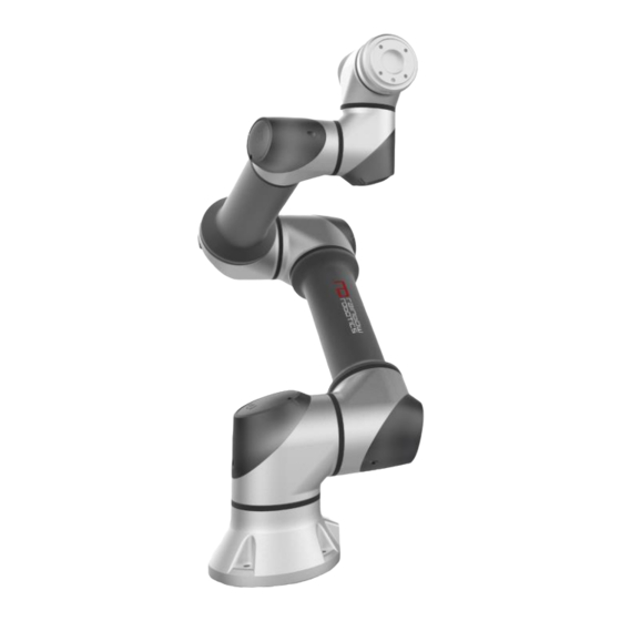
1.3 ROBOT ARM RB series Joint Description ① Name ② Base ③ Base Joint ④ Shoulder Joint ⑤ Elbow Joint ⑥ Wrist 1 Joint ⑦ Wrist 2 Joint ⑧ Wrist 3 Joint Tool Flange © RAINBOW ROBOTICS Inc. All rights reserved. - Page 12 Part for mounting tool or gripper ④ Tool I/O I/O ports to control tool or gripper Base Part for mounting the robot arm ⑤ Connector for cable between Robot arm Connector and Control box © RAINBOW ROBOTICS Inc. All rights reserved.
- Page 13 RAINBOW ROBOTICS RB SERIES _ USER MANUAL Dimensions [ RB5-850E ] [ RB5-850EA1/A2 ] [ RB3-1200E ] [ RB3-1200EA1/A2 ] © RAINBOW ROBOTICS Inc. All rights reserved.
- Page 14 RAINBOW ROBOTICS RB SERIES _ USER MANUAL Dimensions [ RB10-1300E ] [ RB10-1300EA1/A2 ] © RAINBOW ROBOTICS Inc. All rights reserved.
- Page 15 RAINBOW ROBOTICS RB SERIES _ USER MANUAL Configuration of the embedded Pneumatic-tubing/Electric-line in RB5-850EA#, RB3- 1200EA#, and RB10-1300EA#. [ Embedded pneumatic tubing connection ] [ RB5-850EA1, RB3-1200EA1 ] © RAINBOW ROBOTICS Inc. All rights reserved.
- Page 16 RB3-1200EA2 MAX 5EA(4∅ Pneumatic Tube)* 12 Pin(AWG28) RB10-1300EA1 1EA(8∅ Pneumatic Tube) None RB10-1300EA2 1EA(8∅ Pneumatic Tube) 12 Pin(AWG28) * The number of pneumatic lines needs to be adjusted after checking the driving range. © RAINBOW ROBOTICS Inc. All rights reserved.
- Page 17 RAINBOW ROBOTICS RB SERIES _ USER MANUAL Warning: 1) For pneumatic / electric wire passing models, if passing air or power over the defined standard, hardware may be damaged. © RAINBOW ROBOTICS Inc. All rights reserved.
-
Page 18: Control Box
② AC Power Socket (AC POWER) ③ AC Power Switch (AC SWITCH) Connector for Robot Arm cable (ROBOT) ④ Connector for E-STOP/JOG ⑤ (E-STOP/JOG) ⑥ ⑦ Main Switch ⑧ USB/LAN connectors I/O ports © RAINBOW ROBOTICS Inc. All rights reserved. -
Page 19: Teaching Pendant Tablet Pc (Optional)
For stand-type control box ※ Purchasing the tablet PC is not required. The App to operate the RB series can be downloaded from the Rainbow Robotics website. ※ Tablet setup is required for use with RB products. See the Appendix. -
Page 20: Joint Limit
An RB robot unit consists of six joints. The axes of rotation and joint limits are illustrated in the following section. ± 360 Joint Range ° ± 360 ° ± 165 ° ± 360 ° ± 360 ° ± 360 ° © RAINBOW ROBOTICS Inc. All rights reserved. -
Page 21: Workspace
Programing the motion in the joint coordinate system (e.g. Move J) is recommended in this particular area. A. The kinematic singular area. Limits some motion programmed in the inertial coordinate system (e.g. Move L). B. Workspace of the RB unit. © RAINBOW ROBOTICS Inc. All rights reserved. -
Page 22: Maximum Load Capacity
The maximum payload of the robot arm depends on the distance between the Tool flange and the center of mass of the payload. The maximum payload by each specified distance is as follows. © RAINBOW ROBOTICS Inc. All rights reserved. -
Page 23: Chapter 2. Safety & Precautions
Failure to follow the instructions with this symbol may result in an accident, which could result in serious injury to the user. Failure to follow directions marked with this symbol may result in damage to the product or injury to users. © RAINBOW ROBOTICS Inc. All rights reserved. -
Page 24: General Safety Warning & Precautions
9) During the operation of the robot, do not enter the operating range of the robot, and do not touch the robot while it is operating. 10) Never modify the robot without the support of Rainbow Robotics. Rainbow Robotics (hereinafter "the manufacturer") bears no responsibility/liability for any problems caused by user's modification or modification of the product. - Page 25 RB, or damage to other machines due to robot malfunctions. 2) Do not expose the robot to strong magnetic fields as the robot may be damaged. © RAINBOW ROBOTICS Inc. All rights reserved.
- Page 26 2) Do not tear, damage, or remove the cover. Be careful when handling parts or devices with a label attached, as well as surrounding components. 3) To avoid electric shock, do not touch the internal electric parts. © RAINBOW ROBOTICS Inc. All rights reserved.
-
Page 27: Usage & Functionality
Any use in places where the performance of the safety function is insufficient Any use beyond performance / environmental specifications ※ Improper use is not limited to the above items. © RAINBOW ROBOTICS Inc. All rights reserved. -
Page 28: Potential Safety Issues
Injury that may occur due to not fully fastening objects Injury from an object that has detached or dropped from the tool mount ※ The characteristics of potential risks may vary depending on the final system. © RAINBOW ROBOTICS Inc. All rights reserved. -
Page 29: Liability Limitations
Providing technical documents, such as manuals ※ Peripherals are not limited to the above items. Compliance with the safety instructions in this manual does not infer that all potential risks are fully avoidable. © RAINBOW ROBOTICS Inc. All rights reserved. -
Page 30: Shipping & Transportation
2) When transporting the robot arm, strong vibration or shock may damage the system. The robot must be transported using the packaging box provided by the manufacturer. © RAINBOW ROBOTICS Inc. All rights reserved. -
Page 31: Emergency Stop
Users can stop the robot arm immediately by pressing the EMERGENCY STOP button. Re-Activating from Emergency Stop Users can restart after Emergency Stop by turning the EMERGENCY STOP button in clockwise direction. © RAINBOW ROBOTICS Inc. All rights reserved. -
Page 32: User Safety
1) If excessive force is applied to the joints in the non-powered state, beware that the driving part may get overloaded. The manufacturer is not liable for any damage caused by excessive force. © RAINBOW ROBOTICS Inc. All rights reserved. -
Page 33: Safety Controller
RAINBOW ROBOTICS RB SERIES _ USER MANUAL 2.9 SAFETY CONTROLLER The Safety Control System of Rainbow Robotics’ RB5-850E Series, RB3-1200E Series, RB10- 1300E Series follows ISO 13849-1 Cat3. PLd. © RAINBOW ROBOTICS Inc. All rights reserved. -
Page 34: Risk Assessment
© RAINBOW ROBOTICS Inc. All rights reserved. -
Page 35: Chapter 3. Safety Functions
This chapter contains important safety information, which must be read and understood by the integrator of the RB series collaborative robots before the robot is initially powered on. RB series can protect users and devices by providing various safety functions and safety device interfaces. - Page 36 5) The signal from the device mounted on the Tool Flange is not included in the safety function. Do not connect the safety device to the Tool Flange cable. © RAINBOW ROBOTICS Inc. All rights reserved.
-
Page 37: Stop Category
3) For an emergency stop, activation is required. 4) For a protection stop, at least one must be selected from stop categories 0 and 1. 5) For additional protection stops, stop category 2 can be used. © RAINBOW ROBOTICS Inc. All rights reserved. -
Page 38: Functional Safety
3.3 FUNCTIONAL SAFETY The manufacturer recommends the following conditions are met for the installation location. The safety functions of the collaborative robot RB series are used to reduce the risk of the robot system determined by risk assessment. The parameters of the safety function are set at the factory, and the system integrator can change some items based on the risk assessment. - Page 39 - EMS1(Emergency Stop1): This function activates the stop mode when the emergency stop switch of the Teaching Pendant Unit is activated. The stop mode is the SF.2. © RAINBOW ROBOTICS Inc. All rights reserved.
- Page 40 - SSS(Soft Safeguard Stop): This function activates the stop mode when the special I/O ports of the Control Box are activated. Those ports are provided for users to connect their own protective devices. The stop mode is SF.3. © RAINBOW ROBOTICS Inc. All rights reserved.
-
Page 41: Safety Device Mounting Location
RB SERIES _ USER MANUAL 3.4 SAFETY DEVICE MOUNTING LOCATION In addition to the basic emergency stop switch, the RB series can be equipped with additional safety devices required by the system integrator through risk assessment. The safety-dedicated contact terminal consists of 16 ports. This terminal is a redundancy dedicated contact input terminal. - Page 42 This port is used to connect one or more protective stop devices through risk assessment. Protective stop devices must be used according to 5.3.8.3 of ISO 10218-2. Protective stops that occur through SSS are designated as stop category 2. © RAINBOW ROBOTICS Inc. All rights reserved.
-
Page 43: Emergency Stop Switch
RB SERIES _ USER MANUAL 3.5 EMERGENCY STOP SWITCH The collaborative robot RB Series allows the operator to use the emergency stop switch to stop the robot in anticipation of an emergency situation. In the event of an emergency, the robot must be stopped immediately by pressing the emergency stop switch on the top of the pendant. -
Page 44: Operation Mode
RAINBOW ROBOTICS RB SERIES _ USER MANUAL 3.6 OPERATION MODE The operation mode of the collaborative robot RB Series is composed as follows. When entering the automatic mode, you must access it through a password. Initialize Mode [Set-up] Auto Mode... - Page 45 1) For manual operation, the safety slide function must be set. 2) At initial shipment, the safety slide function is deactivated. 3) In addition, when using a 3-position enabling device, it must be used according to 5.8.3 of ISO 10218-1. © RAINBOW ROBOTICS Inc. All rights reserved.
-
Page 46: Operating Environment
In order to keep the robot in a safe state for a long time, it must be used in the following conditions/environment. Maximum allowable operating temperature 50˚C Maximum permissible storage temperature 60 ˚C Minimum allowable operating temperature 0˚C Minimum permissible storage temperature -5˚C Maximum permissible humidity Minimum permissible humidity © RAINBOW ROBOTICS Inc. All rights reserved. -
Page 47: Maintenance Of Safety Functions
1 Month Power device. Check if the 24V fuse is inserted 1 Month normally. Check the condition of the connection cable between the Cable 1 Month safety device and the control box. © RAINBOW ROBOTICS Inc. All rights reserved. - Page 48 RB SERIES _ USER MANUAL Safety Function Board Specification Inside the control box, there is a built-in safety function board to drive the RB series. The information of the LED indicating the operation status of the board is as follows. 48V LED...
-
Page 49: Applied Standards
Safety of machinery – Electrical equipment of IEC 60204-1:2016 machines – Part 1: General requirements Electromagnetic compatibility (EMC) – Part 6-1: Generic standards – Immunity standard for IEC 61000-6-1: 2016 residential, commercial light-industrial environments © RAINBOW ROBOTICS Inc. All rights reserved. - Page 50 Safety of machinery — Safety-related parts of ISO 13849-1: 2015 control systems — Part 1: General principles for design Safety of machinery — Safety-related parts of ISO 13849-2: 2012 control systems — Part 2: Validation © RAINBOW ROBOTICS Inc. All rights reserved.
-
Page 51: Chapter 4. Installation
© RAINBOW ROBOTICS Inc. All rights reserved. -
Page 52: Installation Location
Constant temperature and humidity Limited dust inflow Caution: 1) If the system is not installed in a location that matches the recommendations, the performance and lifespan of the robot may be reduced. © RAINBOW ROBOTICS Inc. All rights reserved. -
Page 53: Examples Of Installation
However, the user must set the angle of installation in the system-setup when installing on a surface that is not a flat horizontal surface. [ Installation on the horizontal surface ] [ Installation on the fixed post ] © RAINBOW ROBOTICS Inc. All rights reserved. -
Page 54: Mounting The Robot
5) If the product is used with the bolts disassembled, or if a bracket etc. is installed incorrectly, the product may become damaged, or the safety of the user may be seriously affected. © RAINBOW ROBOTICS Inc. All rights reserved. -
Page 55: Tool Connection
After fixing the tool to the Tool flange, connect the necessary cables to the I/O ports on either the tool I/O or the Control box I/O. The tool connector uses the Samwoo SW-10W-12 (P) connector. © RAINBOW ROBOTICS Inc. All rights reserved. - Page 56 Digital Input F Green (AWG26) The internal power supply can be set to 0V, 12V, or 24V on the I/O tab of the GUI. Nominal Unit 24V mode 12V mode Current Supply 2000 © RAINBOW ROBOTICS Inc. All rights reserved.
- Page 57 The tools digital inputs use PNP and pull-down resistors. Therefore, when the input port is not connected (floating), the corresponding input port is read as low (0). Electrical specifications are as follows. Nominal Unit Input Voltage Logic Low- Voltage Logic High- Voltage © RAINBOW ROBOTICS Inc. All rights reserved.
- Page 58 The tool analog input measures the voltage in a non-differential manner. The measurement categories are as follows. Nominal Unit Input Voltage Resolution The figure below illustrates how to connect an analog sensor with non-differential voltage output characteristics to the Tool flange. © RAINBOW ROBOTICS Inc. All rights reserved.
- Page 59 2) The cross-sectional view related to the tool flange is illustrated in Appendix C. The tool flange supports RS485 serial communication and supports the following serial communication standard. Baud-Rate 9600, 19200, 38400, 57600, 115200, 1M, 2M. Stop Bit Parity None, Even, Odd © RAINBOW ROBOTICS Inc. All rights reserved.
-
Page 60: Cable Connection
Connect the power cable to the power terminal as shown in the figure below. [ Connecting Part for AC power cable ] The specifications of the power system is as follows. Input Voltage 100 ~ 240 VAC Input Frequency 50 ~ 60 Hz © RAINBOW ROBOTICS Inc. All rights reserved. - Page 61 RB SERIES _ USER MANUAL Caution: 1) Do not unplug the robot cable, power cable, or teaching pendant while the robot is activated. 2) For using AC power, the peripherals should share a common ground. © RAINBOW ROBOTICS Inc. All rights reserved.
-
Page 62: Robot Control Box I/O Overview
1) When tightening the I/O wiring, make sure to turn off the power to the control box in advance. Any damage to the product caused by the user's carelessness (24V power shorts, incorrect wiring, etc.) is not covered by the product warranty. © RAINBOW ROBOTICS Inc. All rights reserved. -
Page 63: Safety Input Configuration
Initial Safety Configuration The robot will be shipped with the initial safety configuration set to default, so that the user can use it without configuring it additionally. The initial safety configuration is as follows. © RAINBOW ROBOTICS Inc. All rights reserved. - Page 64 If the 3-position activation switch is pressed or released, the switch is in the inoperative position and the robot arm will not move. Rainbow Robotics does not provide an Enabling device. An Enabling device is available as an option if the user requires.
-
Page 65: General Purpose Digital I/O Configuration
The figure below shows a way to control electric load by using the digital output. Control of digital input with a button The figure below shows a simple way of connecting a button to the digital input. © RAINBOW ROBOTICS Inc. All rights reserved. - Page 66 If another system provides PNP and uses a common ground, the digital I/O can be configured to communicate with the other system. Its connection is shown in the figure below. Warning: 1) For the details in the technical specifications and wire connection, refer to Appendix D. © RAINBOW ROBOTICS Inc. All rights reserved.
-
Page 67: General Purpose Analog I/O Configuration
Voltage mode Output AOx – AG Voltage AOx – AG Resolution Analog output The analog output can be used to control the speed of conveyor. The figure below illustrates a simple demonstration. © RAINBOW ROBOTICS Inc. All rights reserved. - Page 68 : Normal Operation (the main PC in the control box is ready) 2. Display Box (2): Displays information about robot operation and status. 4. Power Consumption: Indicates the total power consumption in watts (W). System Version Information: System version information. © RAINBOW ROBOTICS Inc. All rights reserved.
-
Page 69: Chapter 5. Get Started
"Normal Operation". To turn off the power, press the main power switch for a few seconds. Caution Caution: 1) Control box uses AC 100 to 240V single phase (50 to 60 Hz). © RAINBOW ROBOTICS Inc. All rights reserved. -
Page 70: Teaching Pendant/Pc On/Off
RB SERIES _ USER MANUAL 5.2 TEACHING PENDANT/PC ON/OFF If the user uses the teaching pendant incorporated in Rainbow Robotics, the teaching pendant and cover are provided. To turn on the teaching pendant, press the power button on the top left corner. -
Page 71: Chapter 6. Software Overview
RB SERIES _ USER MANUAL CHAPTER 6. SOFTWARE OVERVIEW 6.1 UI STRUCTURE The UI (User Interface) program is divided into three screens as follows. Each section allows the user to enter necessary steps. © RAINBOW ROBOTICS Inc. All rights reserved. -
Page 72: Startup Screen Display
The image below shows the Startup screen. The Startup screen will occur while the application loading is processing. Login (Factory-Default login password: 0000) To set up the password or to enable automatic login, go to the "Setup-System- Password" menu. © RAINBOW ROBOTICS Inc. All rights reserved. -
Page 73: Main Screen Display
Play: for running motion and tasks pre-programmed in the Make menu. Setup: for setting up parameters. In the main screen, users can create programs for the robot (Make), move the robot (Play), or set settings (Setup) through each relevant menu. © RAINBOW ROBOTICS Inc. All rights reserved. - Page 74 UI Shutdown button, the application closes. If the robot is activated and Tablet is connected to the tablet PC, the power of the robot will stay turned off as well. © RAINBOW ROBOTICS Inc. All rights reserved.
-
Page 75: Make
※ For more details about icons and configuration, refer to Chapter 7. ※ In the Make menu, the robot will not move unless a button is pressed and held. This feature can be removed in Setup-Interface. © RAINBOW ROBOTICS Inc. All rights reserved. -
Page 76: Play
A program loaded into the Play screen will repeat the number of times specified in Setup-Interface. The operating time at the bottom left of the screen shows the elapsed time. ※ Refer to Chapter 8 for more details about Play mode. © RAINBOW ROBOTICS Inc. All rights reserved. -
Page 77: Setup
The Setup screen allows the user to see/change the robot’s default values, such as sensitivity for collision detection, configuration of the robot installation, range of workspace, tool settings, system log, I/O, coordinate system, etc. ※ Refer to Chapter 9 for more details about Setup. © RAINBOW ROBOTICS Inc. All rights reserved. -
Page 78: Chapter 7. Programming Guide
Can adjust the motion speed of the robot arm (even when the robot is running). Various program functions (command/action/etc.) are located. If you ⑨ click the arrow at the right, more functions will be shown. Determines Jog method – either Smooth mode or Tick mode. © RAINBOW ROBOTICS Inc. All rights reserved. - Page 79 ※ TCP (Tool Center Point): The point defined for the tool center point within the robot’s base coordinate system. It may also be the origin of the end-effector. [ Basic View Mode ] [ Icon Extended View Mode ] © RAINBOW ROBOTICS Inc. All rights reserved.
- Page 80 RAINBOW ROBOTICS RB SERIES _ USER MANUAL [ Program-only Mode ] © RAINBOW ROBOTICS Inc. All rights reserved.
- Page 81 IF, a user can have the robot pause or terminate pause when a condition is true. This icon creates a conditional statement. A user can generate separate motion program branches depending on conditions using IF, Else IF, and Else. © RAINBOW ROBOTICS Inc. All rights reserved.
- Page 82 This icon enables a user to program manually. It is typically used when a user-specific calculation and substitution are needed. This icon adds a comment or memo to the program. © RAINBOW ROBOTICS Inc. All rights reserved.
- Page 83 This icon enables the current value of variables (assigned by ‘Assign’ action) or parameters to be checked. Information is displayed within a pop-up. This icon temporarily changes the values of parameters located in Setup menu at the current program. © RAINBOW ROBOTICS Inc. All rights reserved.
- Page 84 ModBus server. The program can access to a specific IP address in order to request and receive data. The protocol of the ModBus Server is provided separately in the user manual appendix. © RAINBOW ROBOTICS Inc. All rights reserved.
- Page 85 However, this function itself does not move to that position. This feature can jump program flows to a specific location/line. It can return to the starting position or control program flow discontinuously with a specific line number. © RAINBOW ROBOTICS Inc. All rights reserved.
- Page 86 The G code feature is a feature that you can use if you have placed the G code file in the specified folder. The robot will implement the path to that G code. © RAINBOW ROBOTICS Inc. All rights reserved.
- Page 87 Unlike the general/non-stop thread that runs concurrently with the program, This feature calls the event general/non- stop thread that is executed when called from the main program. © RAINBOW ROBOTICS Inc. All rights reserved.
- Page 88 This function operates the robot joint and the external axis at the same time. This function controls the external axis in addition to the robot. Up to 6 can be added. © RAINBOW ROBOTICS Inc. All rights reserved.
- Page 89 This function is used to highlight (mark) the desired program line, so important program lines can be underlined. This function enables to search for other functions used within the program, only searchable in English. © RAINBOW ROBOTICS Inc. All rights reserved.
- Page 90 This feature cuts the selected section. The section can be placed in a different location with the paste command. This feature deletes the selected section. This feature changes edit mode to zoom mode. © RAINBOW ROBOTICS Inc. All rights reserved.
- Page 91 This function allows the user to select the UI mode. Users can select the UI mode based on their level and environment. © RAINBOW ROBOTICS Inc. All rights reserved.
- Page 92 This icon is used to power off the UI. When the tablet PC is connected to the robot, the robot will also be turned off. It is located in the bottom right. Screen Lock function is included in here. © RAINBOW ROBOTICS Inc. All rights reserved.
-
Page 93: Create Teaching Environment
1) Make sure that the control box is turned on and that the emergency stop switch is turned off. If the control box is not on, the indicator light beneath “Device Off” will turn red. © RAINBOW ROBOTICS Inc. All rights reserved. - Page 94 “Network Connecting” flashes yellow when the tablet PC is trying to connect to the control box. “Network Connected” becomes blue when the table PC and control box are connected properly. The “Control” button is also activated once more. © RAINBOW ROBOTICS Inc. All rights reserved.
- Page 95 During initialization, the mechanical joint brake is released. Unlocking the joints will generate a clicking sound. All indicators turn to blue when the robot is ready. ※ When “Robot Operation On” is still in red, follow the instructions contained within the message pop-up. © RAINBOW ROBOTICS Inc. All rights reserved.
- Page 96 The default name of a new project is “default”. Type in a name for the new project and press the “Save” button in the dialog. Note that the new project is not created if the “Save” button is not clicked. © RAINBOW ROBOTICS Inc. All rights reserved.
- Page 97 Tool flange. Without a proper value of the load, ‘Direct- teaching’ may not work properly. 3) In ‘Setup-Interface’, the sensitivity of joint reaction can be adjusted. 4) Make sure that the robot is not moving before using ‘Direct-teaching’. © RAINBOW ROBOTICS Inc. All rights reserved.
- Page 98 TCP Movement in the Cartesian coordinate system Mode 2 with respect to the tool (local) frame TCP Movement in the Cartesian coordinate system Mode 3 with respect to the user coordinate frame. Mode 4 Angular joint movement. © RAINBOW ROBOTICS Inc. All rights reserved.
- Page 99 1) Make sure that there are no obstacles or people in the robot’s workspace before using jogging. 2) It is highly recommended to use the ‘Safety Slider’ feature in ‘Setup-Interface’. This feature is activated as a factory default. © RAINBOW ROBOTICS Inc. All rights reserved.
- Page 100 RAINBOW ROBOTICS RB SERIES _ USER MANUAL [ Jog Mode 1: TCP jog w/ Global coordinate ] [ Jog Mode 2: TCP jog w/ Local coordinate ] © RAINBOW ROBOTICS Inc. All rights reserved.
- Page 101 RAINBOW ROBOTICS RB SERIES _ USER MANUAL [ Jog Mode 3: TCP jog w/ User coordinate ] [ Jog Mode 4: Joint jog w/ joint coordinates ] © RAINBOW ROBOTICS Inc. All rights reserved.
- Page 102 2) Simulation mode only requires the provided tablet and the control box. It does not require the robot arm. 3) When using Real Robot mode, make sure that the nearby environment is clear & safe before operating, as the robot will move. © RAINBOW ROBOTICS Inc. All rights reserved.
- Page 103 After using the Move and Point functions in an empty program, the script field in the UI will look as follows. motion property 1 destination 2 destination Details on each of the Move and Point functions are on the following pages below. © RAINBOW ROBOTICS Inc. All rights reserved.
- Page 104 ▷ MoveJB (Move Joint Blend) : Starting from the initial arm configuration, the arm will move smoothly between each Point without stopping by using the Move J method. © RAINBOW ROBOTICS Inc. All rights reserved.
- Page 105 ● Constant mode maintains the first Point’s TCP configuration (Rx, Ry, and Rz) during movement, only changing the tool’s position (x, y, and z) through the movements. ● Intended mode changes both the configuration and position of the TCP as the arm moves. © RAINBOW ROBOTICS Inc. All rights reserved.
- Page 106 MoveITPL has two modes. Constant mode is to move the tool orientation while maintaining the starting point value. Intended mode is to change the orientation of each tool. The speed can be set separately for each intermediate waypoint. © RAINBOW ROBOTICS Inc. All rights reserved.
- Page 107 MoveL is a mode that uses inverse kinematics to move the trajectory of the terminal (TCP) linearly from the starting point to the target point. 6 Cartesian coordinate values (x, y, z, Rx, Ry, Rz) are the inputs for the target point value. © RAINBOW ROBOTICS Inc. All rights reserved.
- Page 108 MoveITPL, the points other than the arrival point move to the waypoint, creating a trajectory that passes exactly through the waypoint. The trajectory is created without stopping and a separate speed setting is possible for each waypoint. © RAINBOW ROBOTICS Inc. All rights reserved.
- Page 109 2) Certain joints may move faster or be restricted in motion while in the dead zone of the robot. For more information about dead zones, refer to Section 1.7. © RAINBOW ROBOTICS Inc. All rights reserved.
- Page 110 By default, the Move function is set to MoveJ. Click MoveJ in order to change the Move command type. A pop-up will appear as shown below. Select the desired movement type and click the “Close” button to change movement type. © RAINBOW ROBOTICS Inc. All rights reserved.
- Page 111 ※ Since the Cartesian coordinate system consists of six values (x, y, z, Rx, Ry, Rz), all six values will need to be set as sub-items of MoveL, MoveLB, MovePB, MoveJL, and MoveITPL. © RAINBOW ROBOTICS Inc. All rights reserved.
- Page 112 Contains the target joint angle values (in degrees) for all six joints ▷ Linear Movement Type(MoveL, MoveLB, MovePB, MoveJL, MoveITPL) Point : Contains the target destination point (in Cartesian coordinates) for the TCP. © RAINBOW ROBOTICS Inc. All rights reserved.
- Page 113 RB SERIES _ USER MANUAL When a user taps on a Point in the program tree, the Point function pop-up window will appear. The window contains the following fields: Each area is described in the table below. © RAINBOW ROBOTICS Inc. All rights reserved.
- Page 114 Note: the movement is a linear movement type. ● When the movement is completed, a pop-up message will appear. Depending on the Point type (Section 2), button may or may not supported. © RAINBOW ROBOTICS Inc. All rights reserved.
- Page 115 “Set” button (Section 7). ※ An example using the Get function (Section 4) is shown below. 1. Use the Jog / Direct-teaching function to move to the desired posture / position © RAINBOW ROBOTICS Inc. All rights reserved.
- Page 116 RAINBOW ROBOTICS RB SERIES _ USER MANUAL 2. Get current posture / location information by pressing “Get” button © RAINBOW ROBOTICS Inc. All rights reserved.
- Page 117 RAINBOW ROBOTICS RB SERIES _ USER MANUAL 3. Save after confirming reflection ※ An example using the Finish at/Stopping time option (Section 6) is shown below. © RAINBOW ROBOTICS Inc. All rights reserved.
- Page 118 Even if the target point is not reached, the operation is terminated when the Finish at condition occurs and the next command is executed. If condition does not occur during operation, execute the next command after reaching the target point normally. © RAINBOW ROBOTICS Inc. All rights reserved.
- Page 119 >If a joint movement is set to zero, that joint will Relative not move. If all are set to zero, the robot will not move. >The user can also change a joint angle by entering a variable or mathematical operation. >> continue © RAINBOW ROBOTICS Inc. All rights reserved.
- Page 120 / position information based on the selected coordinate system. >For example, if the user’s coordinate system ‘0’ is selected and ‘0’ is entered in all Cartesian coordinate values, TCP moves to the origin of the user coordinate system. © RAINBOW ROBOTICS Inc. All rights reserved.
- Page 121 The figure below shows each different type of Point as displayed in the UI. ▷ Joint Type - Absolute point ① Absolute Option point. ② The robot's posture/angle value is saved through “Get” button. © RAINBOW ROBOTICS Inc. All rights reserved.
- Page 122 RB SERIES _ USER MANUAL ▷ Joint Type – Variable point ① Variable Option point. ② Enables the user to enter the joint angle for the target posture or enter the parameterized information as an equation. © RAINBOW ROBOTICS Inc. All rights reserved.
- Page 123 ② Enables the user to enter how much each joint should move relative to the previous joint angle. All angles are in degrees. In addition, it enables the user to enter parameterized information or formulas. © RAINBOW ROBOTICS Inc. All rights reserved.
- Page 124 ① Absolute Option point. ② Enables the user to save a posture/position by using the “Get”/”Save” button. The reference coordinate system of the Cartesian coordinate system value is the robot base coordinate system. © RAINBOW ROBOTICS Inc. All rights reserved.
- Page 125 ② Enables the user to enter the target Cartesian coordinate values. The user can also enter parameterized information as formulas. The reference coordinate system of the set Cartesian coordinate values is the base coordinate system of the robot arm. © RAINBOW ROBOTICS Inc. All rights reserved.
- Page 126 PT_LAST_TCP, which indicates the last arrival point. Frame_Base, which represents the base coordinate system of the robot arm. The user is also able to choose the user coordinate system or the tool's local coordinate system. © RAINBOW ROBOTICS Inc. All rights reserved.
- Page 127 ③ Selection box for the user coordinate system that the user would like to use as a. also enter variable information. ④ The “Get” button will load in the robot's current posture/position information. reference. based on the selected coordinate system. © RAINBOW ROBOTICS Inc. All rights reserved.
- Page 128 Setting function in the Make screen. 2) Up to 3 user coordinate systems can be set and used. 3) The factory default user coordinate system is the same coordinate system as the robot base coordinate system. © RAINBOW ROBOTICS Inc. All rights reserved.
- Page 129 Switching to another types (Move Joint types-> Move Linear types / Move Linear types-> Move joint types), can be done only when the type (option) of Point function is set to Absolute. © RAINBOW ROBOTICS Inc. All rights reserved.
- Page 130 The following is an example of creating and running a simple program based on the above Move and Point functions. [Step 1] Create a new project. In this case, the name of the project is ‘Test’. [Step 2] © RAINBOW ROBOTICS Inc. All rights reserved.
- Page 131 Click on a Point in the program tree to display the Point setting pop-up window as shown below. [Step 4] In the Point pop-up window, click the “Get” button to update the fields with the current robot posture/angles. Press the “Set” button to save this Point. © RAINBOW ROBOTICS Inc. All rights reserved.
- Page 132 After saving the point, the UI will look as follows. [Step 6] Repeat steps 1 - 4 several times to teach the robot the desired motion. The completed example program will look as follows. © RAINBOW ROBOTICS Inc. All rights reserved.
- Page 133 By holding down the “Approach” button, the robot arm will move to the initial position for the program. Once the robot reaches its starting position, a pop-up message will confirm to the user that the robot has reached its starting position. © RAINBOW ROBOTICS Inc. All rights reserved.
- Page 134 [Step 8] After receiving the pop-up in Step 7, the program is ready to run. Click the “Play" button at the bottom again to run the program. The image below shows the program running. © RAINBOW ROBOTICS Inc. All rights reserved.
- Page 135 2. Click Begin in the Program Tree to open the Begin menu 3. Click the “Get” button to record the current posture, and then click the “Set” button to save the position © RAINBOW ROBOTICS Inc. All rights reserved.
- Page 136 RAINBOW ROBOTICS RB SERIES _ USER MANUAL Warning: 1) When the program is first created, all default starting angles will be set to ‘0’. © RAINBOW ROBOTICS Inc. All rights reserved.
- Page 137 RAINBOW ROBOTICS RB SERIES _ USER MANUAL Collision detection during operation The RB Series has 2 built-in collision detection functions: - External Collision Detection (Environment-Collision Detection) - Internal Collision Detection (Self-Collision Detection) [ External Collision ] [ Internal Collision ] External Collision (Environment Collision Detection) ...
- Page 138 Resume: Checks the status and continues robot operation ● Halt: Exits the program ● Alternatively, tap (hit) on the robot arm twice to continue the operation. This will perform the same function as the ‘Resume’ button. © RAINBOW ROBOTICS Inc. All rights reserved.
- Page 139 The image below shows a situation where the user caused the robot to crash into itself. Just before colliding into itself, the robot will stop, prompting the UI to display a warning in red. © RAINBOW ROBOTICS Inc. All rights reserved.
- Page 140 / predicts a collision. The robot will stop, prompting the UI to display a warning in red. If the robot stops during operation in real mode, please move the robot arm to a safe position with direct teaching function before continuing work. © RAINBOW ROBOTICS Inc. All rights reserved.
- Page 141 The radius of the Axis/Center method is determined by distance between the robot’s most recent position and the center Point. The Circle function offers 4 Orientation Options: Constant, Intended, Smooth, and Radial. © RAINBOW ROBOTICS Inc. All rights reserved.
- Page 142 ■ Radial: Rotates the TCP orientation with respect to the center point of rotation. ■ Smooth: The turn changes immediately from the start point to the destination point. The rotation information of the waypoint is ignored. © RAINBOW ROBOTICS Inc. All rights reserved.
- Page 143 ① Circular Motion type selection (3-point setting type) ② Point type (Absolute / Variable / Relative / UserCoord.) ③ Orientation option (Constant / Radial / Intended / Smooth) ④ Via Point information ⑤ Destination Point information © RAINBOW ROBOTICS Inc. All rights reserved.
- Page 144 ① Circular motion selection (axis / center setting type) ② Point type (Absolute / Variable / Relative / UserCoord.) ③ Orientation option (Constant / Radial / Intended / Smooth) ④ Center point information ⑤ Axis information ⑥ Rotation angle information © RAINBOW ROBOTICS Inc. All rights reserved.
- Page 145 Ex) After a specified amount of time (i.e. 3.0 seconds), the next command is executed. When using ‘sync speed control bar’ function in Sync, the wait time is adjusted in inverse proportion to the speed control bar value. © RAINBOW ROBOTICS Inc. All rights reserved.
- Page 146 Ex.) if the condition is true, the function waits indefinitely The Time Out function prevents the condition from continuing to wait until it becomes False in a situation where it cannot be false. Escape the wait after the written time has elapsed. © RAINBOW ROBOTICS Inc. All rights reserved.
- Page 147 The Time Out function prevents the condition from continuing to wait until it becomes True in a situation where it cannot be true. Escape the wait after the written time has elapsed. © RAINBOW ROBOTICS Inc. All rights reserved.
- Page 148 Users can enter the conditional statement they would like to use in the If statement. Else if (+ Add else if) or Else functionality (+ Add else) can be created along with branch of conditional statements. © RAINBOW ROBOTICS Inc. All rights reserved.
- Page 149 ‘+ Add case’ button. After clicking the ‘+ Add case’ button, the following window will appear. Enter the conditional argument in the field, and then press the ‘Set’ button to save. © RAINBOW ROBOTICS Inc. All rights reserved.
- Page 150 2) Repeat while the specified condition is true 3) Repeat while the specified condition is not true. After clicking the ‘Repeat’ button, a pop-up menu containing the 3 modes will appear. Once it opens, select and use the desired function. © RAINBOW ROBOTICS Inc. All rights reserved.
- Page 151 RAINBOW ROBOTICS RB SERIES _ USER MANUAL 1) Time Condition Ex.) The above example will repeat a subprogram 1 time. © RAINBOW ROBOTICS Inc. All rights reserved.
- Page 152 RB SERIES _ USER MANUAL 2) Holding Condition Ex.) While ANALOG_IN_0 and DIGITAL_IN_1 both evaluate to 1, the subprogram will repeat. The subprogram will continue to repeat until at least one of the two value changes. © RAINBOW ROBOTICS Inc. All rights reserved.
- Page 153 RAINBOW ROBOTICS RB SERIES _ USER MANUAL 3) Exit Condition Ex.) The subprogram will repeat until both ANALOG_IN_0 and DIGITAL_IN_1 evaluate. To.1. The subprogram will continue to repeat until both values become 1. © RAINBOW ROBOTICS Inc. All rights reserved.
- Page 154 ‘Repeat’ function, and when used, it moves to the top of the Repeat without executing the subprogram. It can only be used as a sub-item of the ‘Repeat’ function – it cannot affect any other part of the program. © RAINBOW ROBOTICS Inc. All rights reserved.
- Page 155 In the example below, there is an infinite loop that contains an If function. If the condition (SD_ANALOG_IN_0 < 5) ever evaluates to true, the subprogram escapes the loop and executes the next command (in this case, End). If the condition never occurs, the loop will continuously repeat. © RAINBOW ROBOTICS Inc. All rights reserved.
- Page 156 'SD_ANALOG_IN_0 < 5' is true, the command at the bottom of the Continue function is not executed and the command at the top of the loop is executed (example below shows a 3- seconds wait). © RAINBOW ROBOTICS Inc. All rights reserved.
- Page 157 In the example below, the program will check the If function and call the Halt function if the condition is true. If the condition is true, the program will terminate and will not execute the next commands. © RAINBOW ROBOTICS Inc. All rights reserved.
- Page 158 RAINBOW ROBOTICS RB SERIES _ USER MANUAL Warning: 1) When the Halt function is executed, the main program will terminate – this includes any additional Thread functions. © RAINBOW ROBOTICS Inc. All rights reserved.
- Page 159 Multiple variables can be declared by clicking the ‘Add’ button. To save the variable, click on the Set button. If a declaration is made, the variable name and initial value will be displayed on the tree as shown below © RAINBOW ROBOTICS Inc. All rights reserved.
- Page 160 - For the String type, put use quotations around the string for the initial value (e.g., “hello_rb5”). 4) Button for the Point type. - The 6 coordinates (x, y, z, Rx, Ry, Rz) of the current robot configuration are imported as initial values. © RAINBOW ROBOTICS Inc. All rights reserved.
- Page 161 From here, the user can enter a custom script. If the user wants to execute multiple lines, click the ‘Add’ button at the bottom of the pop-up window. © RAINBOW ROBOTICS Inc. All rights reserved.
- Page 162 To summarize, the robot moves to the first position with MoveJ, saves the position as start_point, and then executes the ‘Repeat’ function 4 times and moves up each loop by 50mm using the MoveL function. © RAINBOW ROBOTICS Inc. All rights reserved.
- Page 163 1) The script function is an area where the user can freely write and execute a script. 2) If the users write a script that doesn't match the syntax, the program may malfunction or stop. Be careful and use the proper syntax when using this feature. © RAINBOW ROBOTICS Inc. All rights reserved.
- Page 164 The ‘Text’ function enables users to make notes/comments in the program list tree. The text function is displayed as green text in the program tree and does not affect the functionality of the program. Click the Text icon to add it to the Program Tree. © RAINBOW ROBOTICS Inc. All rights reserved.
- Page 165 By clicking the Folder icon, it will be added to the program tree. Commands can then be added, as shown below. © RAINBOW ROBOTICS Inc. All rights reserved.
- Page 166 To rename the folder, click on the new Folder in the program tree. A pop-up will appear for the user to change the name. Press Set to save the new name. The program tree will now show the folder with its new name. © RAINBOW ROBOTICS Inc. All rights reserved.
- Page 167 RB SERIES _ USER MANUAL Like the ‘Text’ function, it does not affect the function of the program. This function only enables the flow of the program to be managed by enabling module creation. © RAINBOW ROBOTICS Inc. All rights reserved.
- Page 168 If you click the Sub.P icon in the program, the following pop-up window appears, and at this time, click on ‘Sub.P’. If you click ‘Sub.P’, a pop-up window with file explorer function appears as shown below. © RAINBOW ROBOTICS Inc. All rights reserved.
- Page 169 To see the contents of the subprogram, expand the program tree viewer (shown below in the green dotted lines) and click on the loaded subprogram. The current project is displayed on the left side, and the loaded project contents are displayed on the right side. © RAINBOW ROBOTICS Inc. All rights reserved.
- Page 170 RAINBOW ROBOTICS RB SERIES _ USER MANUAL A subprogram is executed sequentially along with other programs. If other commands are placed after a subprogram, they will be executed after the subprogram finishes. © RAINBOW ROBOTICS Inc. All rights reserved.
- Page 171 If modifications are required, the project must be opened separately. 2) The Sub.P function can be called up to 10 levels deep. It is not recommended to use recursion with the Sub.P function. © RAINBOW ROBOTICS Inc. All rights reserved.
- Page 172 [ Run in Play ] The left column shows the flow of a program being executed in the Make screen, whereas the right column shows the same program being executed in the Play screen. In Make, the © RAINBOW ROBOTICS Inc. All rights reserved.
- Page 173 In the Play screen, the program repeats between Begin and End, but the commands contained within the Pre-Program folder are executed only once. ‘Pre.P’ function is useful for running functions that need to be performed once, such as variable declarations, and communication connections. © RAINBOW ROBOTICS Inc. All rights reserved.
- Page 174 Users cannot copy the Pre.P Folder and paste it elsewhere. Warning: 1) If the ‘Pre.P’ function is used in a project called through the ‘Sub.P’ function in the main program, the ‘Pre.P’ function applies only to the main program. © RAINBOW ROBOTICS Inc. All rights reserved.
- Page 175 The Thread Function will support only up to 3 different threads Thread functionality works only in the current running program. If a subprogram called through a Sub.P function uses a thread, it will not work properly. Thread types are as follows: © RAINBOW ROBOTICS Inc. All rights reserved.
- Page 176 The figure below is an example of how the Thread function can be inserted into an actual project. In the example below, 2 threads are inserted. As shown in the figure above, the event thread starts running when the event thread call function is used in the main program. © RAINBOW ROBOTICS Inc. All rights reserved.
- Page 177 3) When using Pause or Alarm function, both main program and thread are paused. 4) When the main program exits, the thread will also exit – even if the thread has not yet finished executing. © RAINBOW ROBOTICS Inc. All rights reserved.
- Page 178 Enter the title and content of the alarm window. The title will appear at the top of the pop- up, and the content will provide more in-depth information about the alarm. The below image is an example of a user-made Alarm. © RAINBOW ROBOTICS Inc. All rights reserved.
- Page 179 Pressing the Resume button in the pop-up window will resume the program, whereas pressing the Halt button will stop program at this point. When using the alarm function, both the main program and thread programs are paused and at the same time. © RAINBOW ROBOTICS Inc. All rights reserved.
- Page 180 To observe several variables within the same pop-up, press the ‘Add’ button to add another variable. The following is an example on using ‘Debug’. Declare 1 variable-type variable (my_var = 3.14) and 1 array-type variable (my_arr = {100,200,300}) using the ‘Assign’ function as shown below. © RAINBOW ROBOTICS Inc. All rights reserved.
- Page 181 Once the setting is complete, run the program (the tablet PC and the control box must be connected before execution), and the following pop-up window will enable when the © RAINBOW ROBOTICS Inc. All rights reserved.
- Page 182 RB SERIES _ USER MANUAL Debug command is executed. The pop-up will allow the user to observe the specified variable values. Resume: Continues to the next command. Halt: Terminates the program. © RAINBOW ROBOTICS Inc. All rights reserved.
- Page 183 Linear Move Offset Inbox check mode TCP Position Tool Collision Box Global Workspace Inbox size Collision Check On/off Overall speed multiplier Overall acceleration multiplier © RAINBOW ROBOTICS Inc. All rights reserved.
- Page 184 For example, you can use its ‘Collision On / Off’ feature to selectively turn on/off collision detection in the middle of a program flow. © RAINBOW ROBOTICS Inc. All rights reserved.
- Page 185 -Set Function: Collision Threshold Change Temporarily sets the collision detection sensitivity. The lower the value, the more sensitive the robot is to collision. This has the same functionality as the Collision Threshold option within the Setup Menu. © RAINBOW ROBOTICS Inc. All rights reserved.
- Page 186 Payload option within the Setup Menu. -Set Function: Linear Move Offset This function enables a slight offset relative to the base coordinate system. This function is used to temporarily set an offset of up to 20 mm. © RAINBOW ROBOTICS Inc. All rights reserved.
- Page 187 Script, If, or some similar function. Under the “Type” box, choose “Shared Data.” Then under the “List” box, use either the SD_INBOX_TRAP_FLAG_0 (not in the box) or SD_INBOX_TRAP_FLAG_1 (in the box) variables. © RAINBOW ROBOTICS Inc. All rights reserved.
- Page 188 Temporarily set the size and position of a virtual box surrounding the gripper for self- collision prevention. The size and position of the virtual box will be relative to the TCP Position. It has the same functionality as Tool Setting for Collision Check in Setup-Tool. © RAINBOW ROBOTICS Inc. All rights reserved.
- Page 189 Temporarily set the limits of the workspace for collision prevention. It has the same functionality as the Workspace Limits menu in Setup-Cobot. -Set Function: Inbox Size Temporarily set the position and size of the Inbox. It has the same functionality as the Inbox settings in Setup-Inbox. © RAINBOW ROBOTICS Inc. All rights reserved.
- Page 190 -Set Function: Speed Override (speed multiplier) Through this, the user can temporarily change the base scaled speed used by the Move and Point functions. Users can either enter a value between 0 and 2.0, or a predefined variable. © RAINBOW ROBOTICS Inc. All rights reserved.
- Page 191 In the example above, the base speed for Move J is overwritten to be 1.5 times the normal speed, whereas the base speed for Move L is overwritten to be 0.71 times the normal speed. © RAINBOW ROBOTICS Inc. All rights reserved.
- Page 192 Move and Point functions. Users can either enter a value between 0 and 2.0, or a predefined variable. Through the code below, you can see how the speed and acceleration change when Speed Override and Acceleration Override are used. © RAINBOW ROBOTICS Inc. All rights reserved.
- Page 193 RB SERIES _ USER MANUAL -Set Function: Serial Communication Configuration The baud rate and stop bit / parity of the serial communication are temporarily set. It has the same meaning as set in Setup-Serial. © RAINBOW ROBOTICS Inc. All rights reserved.
- Page 194 In this case, it follows the speed / acceleration value set for each point during operation. Ex.) If you need to keep a certain speed and acceleration during operation, you can use this Set function as in the code below. © RAINBOW ROBOTICS Inc. All rights reserved.
- Page 195 RAINBOW ROBOTICS RB SERIES _ USER MANUAL © RAINBOW ROBOTICS Inc. All rights reserved.
- Page 196 / arc will be changed to spiral motion. Therefore, to implement spiral motion, this function should be inserted above the Circle function. Ex 1) Only Circle is used: Create a general circle / arc trajectory © RAINBOW ROBOTICS Inc. All rights reserved.
- Page 197 - Set Function: Speed Bar Control The speed control bar (bottom right) of the UI can be adjusted with the program. The user can change the UI speed control bar by using this function in the desired section. © RAINBOW ROBOTICS Inc. All rights reserved.
- Page 198 Evasion Stop: After the collision is detected, the robot moves a small amount away from the external force and then pauses the trajectory movement. It has the same meaning as Setup-Cobot's "Action after Collision". © RAINBOW ROBOTICS Inc. All rights reserved.
- Page 199 This function temporarily moves the origin of user coordinate system. The user can set the desired user coordinate system number and shift distance to shift and choose which coordinate system to shift the shift distance. © RAINBOW ROBOTICS Inc. All rights reserved.
- Page 200 If you want to terminate the program after collision detection, you can use this function to select the option as Stop state. Pause State: Program flow is paused after external collision detection. Stop State: Program flow stops after external collision detection. © RAINBOW ROBOTICS Inc. All rights reserved.
- Page 201 It can be used for development testing, etc., and by selecting an option, the output can be deactivated/activated according to the program section. © RAINBOW ROBOTICS Inc. All rights reserved.
- Page 202 100mm. This is a sub-function of the ‘Set’ function, which can be activated/deactivated for each section of the program. If the user wants to disable it, select None in the coordinate system. © RAINBOW ROBOTICS Inc. All rights reserved.
- Page 203 As a sub-function of the Set function, this function can be turned on or off depending on the program section. This function is used to uniformly rotate the TCP rotation at a time. © RAINBOW ROBOTICS Inc. All rights reserved.
- Page 204 By selecting three points in the middle of the program flow, the user coordinate system setting can be arbitrarily changed in the middle of the program. Since it is a sub-function of Set, the user coordinate system setting returns to the default value when the program ends. © RAINBOW ROBOTICS Inc. All rights reserved.
- Page 205 At this time, select whether to apply this shift only to L type or to both L type and J type. As a sub-function of the ‘Set’ function, the setting returns to the default value when the program ends. © RAINBOW ROBOTICS Inc. All rights reserved.
- Page 206 RAINBOW ROBOTICS RB SERIES _ USER MANUAL © RAINBOW ROBOTICS Inc. All rights reserved.
- Page 207 At this time, select whether to apply this shift only to L type or to both L type and J type. As a sub-function of the ‘Set’ function, the setting returns to the default value when the program ends. © RAINBOW ROBOTICS Inc. All rights reserved.
- Page 208 This function is used you to temporarily exclude collision detection by vibration during collision detection. As a sub-function of the ‘Set’ function, the setting returns to the default value when the program ends. © RAINBOW ROBOTICS Inc. All rights reserved.
- Page 209 Create the desired input by setting the state of the port to which you want to input. As a sub-function of the ‘Set’ function, the setting returns to the default value when the program ends. © RAINBOW ROBOTICS Inc. All rights reserved.
- Page 210 This function is used to pause and restart a program that is running, without using alarms and I/O. As a sub-function of the ‘Set’ function, the setting returns to the default value when the program ends. © RAINBOW ROBOTICS Inc. All rights reserved.
- Page 211 High acceleration mode reduces the time the robot's operating speed reaches the desired operating speed through changes in the reduction/acceleration profile. This function is used to pause and restart a program that is running, without using alarms and I/O. © RAINBOW ROBOTICS Inc. All rights reserved.
- Page 212 At this time, it is possible to increase the time but not to reduce it. This function is used to pause and restart a program that is running, without using alarms and I/O. © RAINBOW ROBOTICS Inc. All rights reserved.
- Page 213 In Setup, the sensitivity that made collision detection the most sensitive is also 30% more sensitive than 0%. This function is used to pause and restart a program that is running, without using alarms and I/O. © RAINBOW ROBOTICS Inc. All rights reserved.
- Page 214 User can give a slight offset based on the desired coordinate system. This function enables temporary offset settings of up to 20 mm. This function is used to pause and restart a program that is running, without using alarms and I/O. © RAINBOW ROBOTICS Inc. All rights reserved.
- Page 215 This function is used to temporarily shift the user coordinate, or to temporarily change the position and rotation of the user's coordinate. This function is used to pause and restart a program that is running, without using alarms and I/O. © RAINBOW ROBOTICS Inc. All rights reserved.
- Page 216 This function allows the user to change the user coordinate to the last TCP frame. It is also possible to return to the default user coordinate. This function is used to pause and restart a program that is running, without using alarms and I/O. © RAINBOW ROBOTICS Inc. All rights reserved.
- Page 217 User can select the timer their want to use and set the initial value of the timer. The timer starts from the initial value set by the user. This function is used to pause and restart a program that is running, without using alarms and I/O. © RAINBOW ROBOTICS Inc. All rights reserved.
- Page 218 This is used to set the move speed of the robot in the no-arc state where welding is not performed. This function is used to pause and restart a program that is running, without using alarms and I/O. © RAINBOW ROBOTICS Inc. All rights reserved.
- Page 219 High: Sets the output signal to the high (1) level (green). ④ Enables the user to review the settings selected within the target signal menu. A further explanation is shown below. ⑤ Saves the settings specified within target signal menu. © RAINBOW ROBOTICS Inc. All rights reserved.
- Page 220 (to the right). Then, press the Preview button. As shown above, the Current Signal menu will change to match the settings that the user has put in the Target Signal menu. © RAINBOW ROBOTICS Inc. All rights reserved.
- Page 221 (to the right). Then, press the Preview button. As shown above, the Current Signal menu will change to match the settings that the user has put in the Target Signal menu. © RAINBOW ROBOTICS Inc. All rights reserved.
- Page 222 (to the right). Then, press the Preview button. As shown above, the Current Signal menu will change to match the settings that the user has put in the Target Signal menu. © RAINBOW ROBOTICS Inc. All rights reserved.
- Page 223 (to the right). Then, press the Preview button. As shown above, the Current Signal menu will change to match the settings that the user has put in the Target Signal menu. © RAINBOW ROBOTICS Inc. All rights reserved.
- Page 224 (to the right). Then, press the Preview button. As shown above, the Current Signal menu will change to match the settings that the user has put in the Target Signal menu. © RAINBOW ROBOTICS Inc. All rights reserved.
- Page 225 -Digital Out : Pulse Width Modulation(PWM) The PWM (Pulse Width Modulation) function is used to set the frequency and duty ratio of a PWM pulse, and then send that signal through digital output port. Example 1) © RAINBOW ROBOTICS Inc. All rights reserved.
- Page 226 RB SERIES _ USER MANUAL Example 2) In addition to using the D.out function, users can create a command to export digital output using the Script function as shown below. ※ Function: manual_digital_out (port number, output level) © RAINBOW ROBOTICS Inc. All rights reserved.
- Page 227 4) Before using the digital output, be sure to fully understand the electrical properties of the digital output port provided by the manufacturer. © RAINBOW ROBOTICS Inc. All rights reserved.
- Page 228 ③ Enables the user to preview the settings selected within the target signal menu. A. enter the desired voltage (0 ~ 10V). ④ Saves the settings specified within target signal menu. further explanation is shown below. © RAINBOW ROBOTICS Inc. All rights reserved.
- Page 229 (to the right). Then, press the Preview button. As shown above, the Current Signal menu will change to match the settings that the user has put in the Target Signal menu. © RAINBOW ROBOTICS Inc. All rights reserved.
- Page 230 1) If you want to leave a comment about the An.out function you set, you can use the memo function at the top right of the pop-up window. 2) Before using the analog output, please fully understand the electrical properties of the analog output port provided by the manufacturer. © RAINBOW ROBOTICS Inc. All rights reserved.
- Page 231 In addition, the level of voltage to be output from the tool flange (0V or 12V or 24V) can be adjusted together. Click the Tool Icon to add it to the program. Click on Tool in the program tree to have the following pop-up window appear. © RAINBOW ROBOTICS Inc. All rights reserved.
- Page 232 With the control box connected to the teaching pendant, and after activating the robot, set the Target Signal menu as shown above. Then press the Preview button to preview the tool flange output signal. © RAINBOW ROBOTICS Inc. All rights reserved.
- Page 233 1) The user can add a comment about the Tool.out function by using the memo function at the top right of the pop-up window. 2) Before using the tool flange output, please fully understand the electrical properties of the port provided by the manufacturer. © RAINBOW ROBOTICS Inc. All rights reserved.
- Page 234 RS485 or using CRC. Add the gripper function to the program tree and click the added Gripper as below. © RAINBOW ROBOTICS Inc. All rights reserved.
- Page 235 2. Select gripper connection point(Control Box, Tool Flange). 3. Select the function to be used as the gripper. Warning: The product list provided in the gripper function will be updated through user request. © RAINBOW ROBOTICS Inc. All rights reserved.
- Page 236 Users can output in ASCII mode, or in HEX mode. The UI Tablet (Teaching pendant) only supports UI485 Tx. The configuration can be previewed through the Preview button on the right side of the pop-up window. [ ASCII mode ] © RAINBOW ROBOTICS Inc. All rights reserved.
- Page 237 Setup-serial menu. Alternatively, the user can use the Set-Serial_Configuration option at the top of the project. To use serial communication on the box side, plug a commercially available USB-Serial (RS232 / 422/485) device into the USB port. © RAINBOW ROBOTICS Inc. All rights reserved.
- Page 238 Open: Opens socket and connects with server. Read ASCII Variable: Reads a value sent from the server. The user will need to choose a variable to be overwritten with the received value. © RAINBOW ROBOTICS Inc. All rights reserved.
- Page 239 Read ASCII Array: Reads an array sent from the server and puts it into an array type. Read String: Reads a string from the server and puts it into a string type. Send String: Send the specified string to the server. © RAINBOW ROBOTICS Inc. All rights reserved.
- Page 240 RAINBOW ROBOTICS RB SERIES _ USER MANUAL -Socket Function: Close This option closes the selected socket (0 ~ 4). © RAINBOW ROBOTICS Inc. All rights reserved.
- Page 241 This opens the selected socket (0 ~ 4) and connects to the partner server. This option requires the user to set the IP address and port number of the server they would like to connect to. © RAINBOW ROBOTICS Inc. All rights reserved.
- Page 242 Through this, the user can select one predefined variable (from the ‘Assign’ function) and overwrite the value of that variable with a value received from the server. (Note: specific rules apply. These rules can be found at the end of the ‘Socket’ function section.) © RAINBOW ROBOTICS Inc. All rights reserved.
- Page 243 (Note: specific rules apply. These rules can be found at the end of the Socket Function section.) © RAINBOW ROBOTICS Inc. All rights reserved.
- Page 244 This is the function to put the ASCII string received through Socket communication into the selected string variable. (Note: specific rules apply. These rules can be found at the end of the Socket Function section.) © RAINBOW ROBOTICS Inc. All rights reserved.
- Page 245 RB SERIES _ USER MANUAL -Socket Function: Send String Through this, the user can send a specific string to the server by either entering a string directly in the field, or sending a predefined string type variable. © RAINBOW ROBOTICS Inc. All rights reserved.
- Page 246 (e.g. “this_is_string_from_server”) Internal variables to enable socket communication: The RB series comes with built in variables for users to check information regarding the status of the sockets, as well as the data coming through those sockets. The internal variables are shown below. They can be accessed using the Script Function, or some similar function (i.e.
- Page 247 RAINBOW ROBOTICS RB SERIES _ USER MANUAL (SD_SOCK_LAST_READ_0). This variable will have a value of zero if no data came from the server. The figure below shows an example of the Socket Function. © RAINBOW ROBOTICS Inc. All rights reserved.
- Page 248 ② Select the signal type (Read bit (1bit), Read word (16bit), Write bit (1bit), Write ③ Input the address of the endpoint connection on the server. word (16bit)). ④ Select the frequency of read / write requests per minute (Hz). © RAINBOW ROBOTICS Inc. All rights reserved.
- Page 249 This writes the bit value (1 bit) stored in the variable mod_write_bit to address 456 on the server (IP: 1.2.3.4) and will write the data at a rate of 50 times per second (50 Hz). © RAINBOW ROBOTICS Inc. All rights reserved.
- Page 250 ② Set the direction for the conveyor movement (x, y, z value is based on robot arm base coordinate system). The robot will move at the specified speed in the specified direction until the conveyor movement ends. © RAINBOW ROBOTICS Inc. All rights reserved.
- Page 251 RAINBOW ROBOTICS RB SERIES _ USER MANUAL An example program tree using the Conveyor Function will look as follows: © RAINBOW ROBOTICS Inc. All rights reserved.
- Page 252 The Post.P Function allows the user to insert a command that will be executed after the program has completed. The instructions declared within the Post.P function are sequentially executed after the program terminates. The execution of Post.P proceeds as shown in the diagram below. © RAINBOW ROBOTICS Inc. All rights reserved.
- Page 253 Low signal before the end of the program. By using the PostP. function, when the program terminates, port 1 will automatically send a Low signal. As in the above example, the Post.P function can be used for safety functions. © RAINBOW ROBOTICS Inc. All rights reserved.
- Page 254 Commands related to the movement of the robot arm, such as MoveJ and MoveL, cannot be used within Post.P Post.P works only within a top-level program. If a subprogram invokes the Post.P function, the Post.P portion of the subprogram will not be executed. © RAINBOW ROBOTICS Inc. All rights reserved.
- Page 255 Template function can be modified in the current program. If you click the Sub.P icon in the program, the following pop-up window appears. At this time, click ‘Template’. Assume that a project named “sample_prog” has been created as shown below. © RAINBOW ROBOTICS Inc. All rights reserved.
- Page 256 RAINBOW ROBOTICS RB SERIES _ USER MANUAL example 1) sample_prog is called by Sub.P example 2) sample_prog is called by Template © RAINBOW ROBOTICS Inc. All rights reserved.
- Page 257 If the file is imported by the Template function as shown in Ex.2), it is loaded in a form that can be modified in the current program. Once copied to the template, the contents of the copied subprogram are not changed even if the original is modified. © RAINBOW ROBOTICS Inc. All rights reserved.
- Page 258 By using the Monitor function, the user can select the ‘my_count’ variable as the object to observe. As shown in the above image, in the Monitoring window, the user can enter the name of the variable to be observed. © RAINBOW ROBOTICS Inc. All rights reserved.
- Page 259 If the user wants to observe the value of the monitored variable, they can click the Monitor icon on the right side of the screen. After that, if the user presses the play (▷) button, they can observe the value of ‘my_count’ increasing every second. © RAINBOW ROBOTICS Inc. All rights reserved.
- Page 260 Pattern Action: This setting defines the motion relative to the reference point set in the Pattern Anchor. The defined relative behavior is repeated at every pattern point set in the Pattern Property. © RAINBOW ROBOTICS Inc. All rights reserved.
- Page 261 RAINBOW ROBOTICS RB SERIES _ USER MANUAL The following is an example of Pattern function. Step 1) Set the Pattern Property as shown below. © RAINBOW ROBOTICS Inc. All rights reserved.
- Page 262 Step 2) Using the Pattern Anchor and the Pattern Action, define the relative movement as below. Step 3) Repetitive behavior is completed as relative movement set in Step-2 is applied in all pattern points set in Step-1. © RAINBOW ROBOTICS Inc. All rights reserved.
- Page 263 PinPoint name, the posture information is converted into a Point variable. The information saved as Point variable can be used in other operation commands/settings. © RAINBOW ROBOTICS Inc. All rights reserved.
- Page 264 Move program flow to a specific line number. Option) Jump To / Here Move program flow to a specific address value. Jump To calls the address value you want to move, and JumpHere writes the address value. © RAINBOW ROBOTICS Inc. All rights reserved.
- Page 265 RAINBOW ROBOTICS RB SERIES _ USER MANUAL © RAINBOW ROBOTICS Inc. All rights reserved.
- Page 266 This function is to play the recorded teaching motion. Motion recording is performed in the settings of the Make page. If you select the name and motion speed/property of the recorded motion, the recorded motion is played again. © RAINBOW ROBOTICS Inc. All rights reserved.
- Page 267 The left side of the figure below is for normal operation only. If this motion is put as a sub- item of weaving, TCP trajectory reflecting the weaving trajectory is drawn (in the example on the right, in the case of triangle wave weaving). © RAINBOW ROBOTICS Inc. All rights reserved.
- Page 268 (when setting the force control to the ground). [ Before applying force control ] [ After applying force control ] © RAINBOW ROBOTICS Inc. All rights reserved.
- Page 269 As illustrated above, this feature enables quick and easy insertion of weld speed/weld current / voltage settings / safety signal processing options into the program to be used for welding. © RAINBOW ROBOTICS Inc. All rights reserved.
- Page 270 This enables the ability to change the TCP value during program execution with the TCP value pre-saved in Setup' Tool List. It does not change again until the TCP value is replaced or the program is shut down. © RAINBOW ROBOTICS Inc. All rights reserved.
- Page 271 This feature enables direct teaching during program execution. For ‘Mode On’, the program pauses when the manual direct teaching command is executed and a pop-up window appears on the screen as shown below. © RAINBOW ROBOTICS Inc. All rights reserved.
- Page 272 ② If you used the direct teaching feature in ①, turn off the direct teaching function and ① Use the direct teaching feature while the program is paused. resume the program. ③ Ignore the manual operation and resume the program. ④ Exit the program. © RAINBOW ROBOTICS Inc. All rights reserved.
- Page 273 Enter the name of the G code file that user saved in File Name. The plane in which the robot moves can then specify the xy, yz, and zx planes of the user-specified coordinate system as the starting planes. © RAINBOW ROBOTICS Inc. All rights reserved.
- Page 274 Mulic Player PLC(XGT Protocol) - LS Electric PLC CSV File Pickit Modbus Client(Interrupt) Because each external device has different detailed features available, you should refer to the following information. © RAINBOW ROBOTICS Inc. All rights reserved.
- Page 275 IP address, and port. The user can also decide whether to turn on or ignore alarm pop-up in the event of a connection failure or communication error and set a communication timeout time. © RAINBOW ROBOTICS Inc. All rights reserved.
- Page 276 RAINBOW ROBOTICS RB SERIES _ USER MANUAL HMI(MemLink) - Write Single variable This enables the ability to enter values for one address of HMI. Enter a number or variable name for the transfer value. © RAINBOW ROBOTICS Inc. All rights reserved.
- Page 277 RB SERIES _ USER MANUAL HMI(MemLink) - Read Single variable This enables the ability to read values from one address in HMI. The read values are stored in the variable you specify (Variable). © RAINBOW ROBOTICS Inc. All rights reserved.
- Page 278 This enables the ability to enter numbers from the starting address of the HMI to the specified number of addresses. The pre-declared array must be written to Array Name and should not exceed the maximum length of the array, 20 © RAINBOW ROBOTICS Inc. All rights reserved.
- Page 279 This enables the ability to read data from the starting address of HMI to the specified number of addresses. The pre-declared array must be written to Array Name and should not exceed the maximum length of the array, 20. © RAINBOW ROBOTICS Inc. All rights reserved.
- Page 280 The user will enter the socket number, IP address, port, and protocol type. The user can also decide whether to turn on or ignore alarm pop-up in the event of a connection failure or communication error and set a communication timeout time. © RAINBOW ROBOTICS Inc. All rights reserved.
- Page 281 RB SERIES _ USER MANUAL PLC(MC Protocol) - Write Single variable This enables the ability to enter values for one address of PLC. Enter a number or variable name for the transfer value. © RAINBOW ROBOTICS Inc. All rights reserved.
- Page 282 RAINBOW ROBOTICS RB SERIES _ USER MANUAL PLC(MC Protocol) - Read Single variable The ability to read values from one address in PLC. The read values are stored in the variable you specify (Variable). © RAINBOW ROBOTICS Inc. All rights reserved.
- Page 283 This enables the ability to enter numbers from the starting address of the PLC to the specified number of addresses. The pre-declared array must be written to Array Name and should not exceed the maximum length of the array, 20. © RAINBOW ROBOTICS Inc. All rights reserved.
- Page 284 This enables the ability to read data from the starting address of PLC to the specified number of addresses. The pre-declared array must be written to Array Name and should not exceed the maximum length of the array, 20. © RAINBOW ROBOTICS Inc. All rights reserved.
- Page 285 This function plays an mp3 file while the program is running. The Music driver must be installed through the RB Driver, and the mp3 file you want to play must exist in the specified path. © RAINBOW ROBOTICS Inc. All rights reserved.
- Page 286 The user will enter the socket number, IP address, port, and protocol type. The user can also decide whether to turn on or ignore alarm pop-up in the event of a connection failure or communication error and set a communication timeout time. © RAINBOW ROBOTICS Inc. All rights reserved.
- Page 287 RB SERIES _ USER MANUAL PLC(XGT Protocol) - Write Single variable This enables the ability to enter values for one address of PLC. Enter a number or variable name for the transfer value. © RAINBOW ROBOTICS Inc. All rights reserved.
- Page 288 RB SERIES _ USER MANUAL PLC(XGT Protocol) - Read Single variable This enables the ability to read values from one address in PLC. The read values are stored in the variable you specify (Variable). © RAINBOW ROBOTICS Inc. All rights reserved.
- Page 289 This enables the ability to enter numbers from the starting address of the PLC to the specified number of addresses. The pre-declared array must be written to Array Name and should not exceed the maximum length of the array, 20. © RAINBOW ROBOTICS Inc. All rights reserved.
- Page 290 This enables the ability to read data from the starting address of PLC to the specified number of addresses. The pre-declared array must be written to Array Name and should not exceed the maximum length of the array, 20. © RAINBOW ROBOTICS Inc. All rights reserved.
- Page 291 RAINBOW ROBOTICS RB SERIES _ USER MANUAL CSV File - Read String This function reads a string from a CSV file. The CSV file must be saved within the specified path. © RAINBOW ROBOTICS Inc. All rights reserved.
- Page 292 RAINBOW ROBOTICS RB SERIES _ USER MANUAL CSV File - Read Single Variable This function reads a single number from a CSV file. The CSV file must be saved within the specified path. © RAINBOW ROBOTICS Inc. All rights reserved.
- Page 293 This function connects communications between the Pickit and the RB system. The user will enter the socket number, IP address, and port. The user can also decide whether to turn on or ignore alarm pop-up in the event of a connection failure or communication error. © RAINBOW ROBOTICS Inc. All rights reserved.
- Page 294 RAINBOW ROBOTICS RB SERIES _ USER MANUAL Pickit - Send Command Set the command to be sent to Pickit and the data according to the command. © RAINBOW ROBOTICS Inc. All rights reserved.
- Page 295 IP address, and port. The user can also decide whether to turn on or ignore alarm pop-up in the event of a connection failure or communication error and set a communication timeout time. © RAINBOW ROBOTICS Inc. All rights reserved.
- Page 296 Modbus Client(Interrupt) - Write Single variable This function is used to input word type data to one address through Modbus communication. At this time, enter the name of a number or variable for the transfer value. © RAINBOW ROBOTICS Inc. All rights reserved.
- Page 297 Modbus Client(Interrupt) – Read Single Variable This function is used to input word type data to one address through Modbus communication. At this time, enter the name of a number or variable for the transfer value. © RAINBOW ROBOTICS Inc. All rights reserved.
- Page 298 This function is used to input word data from the start address to the specified number of addresses through Modbus communication. At this time, the previously declared array should be written in ‘Array Name’ and the length should not exceed 20, the maximum length of the array. © RAINBOW ROBOTICS Inc. All rights reserved.
- Page 299 This function reads data from the start address to the specified number of addresses through Modbus communication. At this time, the previously declared array should be written in ‘Array Name’ and the length should not exceed 20, the maximum length of the array. © RAINBOW ROBOTICS Inc. All rights reserved.
- Page 300 RB SERIES _ USER MANUAL ■ Extension Board Function : This feature controls digital/analog output when purchasing and using an extended I/O module. The method of use is the same as the existing D.output and An.output. © RAINBOW ROBOTICS Inc. All rights reserved.
- Page 301 RB SERIES _ USER MANUAL ■ User Input Function : This feature is used when a user wants to randomly change the value of a specific variable while the program is running. Available for Variable/Array/Point/String/Global/ROM variables. © RAINBOW ROBOTICS Inc. All rights reserved.
- Page 302 ① Resume the program without replacing the corresponding variable. ② Enter the data you want to change in 'Applied Values', then press to reflect the data you entered in 'Applied Values', and then resume the program. ③ Exit the program. © RAINBOW ROBOTICS Inc. All rights reserved.
- Page 303 Touch sensing is intended to utilize welding applications and detects the movement of the base material and reflects the direction of movement of the base material and is used for welding. A detailed description of this feature is provided in a separate manual. © RAINBOW ROBOTICS Inc. All rights reserved.
- Page 304 At this time, the user can select the movement type. When going to the Project Home Posture, the user can select Project Home Posture of the main program and Project Home Posture of the subprogram. © RAINBOW ROBOTICS Inc. All rights reserved.
- Page 305 The diagram below shows the difference between the case of going to the Project Home Posture of the main project and the case of going to the Project Home Posture of the subproject when using the home function within the subprogram. © RAINBOW ROBOTICS Inc. All rights reserved.
- Page 306 RB SERIES _ USER MANUAL ■ D.Weld : This function enables the use of the digital weld machine. After selecting the weld machine to be used, user can proceed with ‘Weld Start’, ‘Weld Off’, and ‘Weld Setting’. © RAINBOW ROBOTICS Inc. All rights reserved.
- Page 307 This function is used to run the event thread in the main program. The event thread is executed only when the event thread call is executed in the main program. In this case, the number of the event thread to be executed can be selected. © RAINBOW ROBOTICS Inc. All rights reserved.
- Page 308 ‘Call by program switching method’. If you select the program you want to switch to in the file explorer pop-up that appears after clicking, the command is created as shown below. © RAINBOW ROBOTICS Inc. All rights reserved.
- Page 309 Step1) Select the command to cut. The selected command will be shown in blue. In below the example, the MoveL line is selected. Step2) Press the Cut button. Once Cut is clicked, the line disappears from the program tree. © RAINBOW ROBOTICS Inc. All rights reserved.
- Page 310 Step1) Select the item to copy. The selected command will be shown in blue. In the below example, the MoveJ line is selected. Step2) Press the Copy button. Step3) Click desired location and click the Paste button. In the example, the MoveJ command is pasted under the Folder. © RAINBOW ROBOTICS Inc. All rights reserved.
- Page 311 Step2) Click the Del button. The command has been removed as shown below. Step1) Select the command to move. The selected command is shown in blue. In this example, MoveJ at the top is selected. © RAINBOW ROBOTICS Inc. All rights reserved.
- Page 312 In this example, the MoveL command is selected. Step2) Click the Pass icon. The command turns dark as shown below and will not be executed. To undo it, simply select the command again and press the Pass button again. © RAINBOW ROBOTICS Inc. All rights reserved.
- Page 313 RAINBOW ROBOTICS RB SERIES _ USER MANUAL 7.6 PROGRAM MANAGEMENT Allows the user to save, load, or create a project. Save Project © RAINBOW ROBOTICS Inc. All rights reserved.
- Page 314 Note: Only recently used files will appear in the list. To open a file, users can click the Load option. Clicking Other Program button will open the File Explorer, which allows the user to look through saved files. © RAINBOW ROBOTICS Inc. All rights reserved.
- Page 315 Using this window, users can save their current file with the desired program name. The program name cannot bet set to “default,” as it is already in use by the system. © RAINBOW ROBOTICS Inc. All rights reserved.
- Page 316 Monitor: Provides a window that allows the user to monitor both system and user variables in real time. UI Mode: UI mode can be selected according to the user's level and the user's purpose. © RAINBOW ROBOTICS Inc. All rights reserved.
- Page 317 Up to 20 frequently used postures can be saved and used on the UI tablet. Press the Get button to get the current position information and press the Set button to save it. Hold down the Move button to move to the saved position. © RAINBOW ROBOTICS Inc. All rights reserved.
- Page 318 RAINBOW ROBOTICS RB SERIES _ USER MANUAL [Utility-Input Signal View] Input signal monitoring window for control box and tool flange. [Utility-Output Signal View] Output signal monitoring window for control box and tool flange. © RAINBOW ROBOTICS Inc. All rights reserved.
- Page 319 This window allows the user to see the robot arm’s current and temperature. It also shows the user coordinate system settings. [Utility-Snap] Snap mode selection window to be applied when using direct teaching mode. © RAINBOW ROBOTICS Inc. All rights reserved.
- Page 320 RB SERIES _ USER MANUAL [Utility-Box Output Test] This window allows you to test the output of the control box. [Utility-Tool Output Test] This window is used to test the output of the tool flange. © RAINBOW ROBOTICS Inc. All rights reserved.
- Page 321 RAINBOW ROBOTICS RB SERIES _ USER MANUAL [Utility-I/O Extension Board] I/O expansion module's I/O signal monitoring window. Window for testing the output of the I/O expansion module. © RAINBOW ROBOTICS Inc. All rights reserved.
- Page 322 RAINBOW ROBOTICS RB SERIES _ USER MANUAL ■ Setting sub functions [Setting-Tool List Select] There is a Tool List Select setup feature that sets up TCP to use in a pre-saved TCP list. © RAINBOW ROBOTICS Inc. All rights reserved.
- Page 323 RAINBOW ROBOTICS RB SERIES _ USER MANUAL [Setting-Joystick] The Joystick setting allows the user to control the robot using a joystick connection. © RAINBOW ROBOTICS Inc. All rights reserved.
- Page 324 RAINBOW ROBOTICS RB SERIES _ USER MANUAL [Setting-User Coordinate] Allows the user to set their own coordinate system using the 3-point setting mode. For more explanation, see the Coordinate page on the Setup Screen. © RAINBOW ROBOTICS Inc. All rights reserved.
- Page 325 Maintains the rotation of the coordinate system. Orientation ( ̊ ) – Change the orientation of the user-defined coordinate system. Maintains the X, Y, and Z of the coordinate system. © RAINBOW ROBOTICS Inc. All rights reserved.
- Page 326 This function allows the user to find the position of the TCP automatically. If the user enters 4 different postures that maintain TCP to be set as the same point on three-dimensional space, the function automatically calculates the position of the TCP. © RAINBOW ROBOTICS Inc. All rights reserved.
- Page 327 RAINBOW ROBOTICS RB SERIES _ USER MANUAL [Setting-External F/T] This window allows you to check and calibrate the external F/T sensor (e.g. Robotiq F/T sensor). © RAINBOW ROBOTICS Inc. All rights reserved.
- Page 328 RAINBOW ROBOTICS RB SERIES _ USER MANUAL [Setting-Auto COG / Mass] This function finds the weight and center of gravity attached to the tool using the internal / external F/T sensor. © RAINBOW ROBOTICS Inc. All rights reserved.
- Page 329 RAINBOW ROBOTICS RB SERIES _ USER MANUAL [Setting-Motion Recording] This function records the motion through the direct-teaching(gravity compensation) function. The recorded action is available in the program via the Replay function. © RAINBOW ROBOTICS Inc. All rights reserved.
- Page 330 RAINBOW ROBOTICS RB SERIES _ USER MANUAL [Setting-I/O Logging] This function sets one digital input/output, records the change in the value of that input/output, and graphically shows it. © RAINBOW ROBOTICS Inc. All rights reserved.
- Page 331 RAINBOW ROBOTICS RB SERIES _ USER MANUAL [Setting-Welder Wire Control] This function can control the welding machine's wire. © RAINBOW ROBOTICS Inc. All rights reserved.
- Page 332 RAINBOW ROBOTICS RB SERIES _ USER MANUAL [Setting-TCP Orientation Change] The rotation direction of the default TCP coordinate system is set based on the current robot pose to match the selected coordinate system. © RAINBOW ROBOTICS Inc. All rights reserved.
- Page 333 RAINBOW ROBOTICS RB SERIES _ USER MANUAL [Setting-User Coordinate Auto] Changes the coordinate system setting to the current TCP frame. © RAINBOW ROBOTICS Inc. All rights reserved.
- Page 334 By pressing the recording function on the upper right, the TCP trace of the robot tool is recorded in the 3D viewer in the 3D viewer. (Yellow solid line) © RAINBOW ROBOTICS Inc. All rights reserved.
- Page 335 RAINBOW ROBOTICS RB SERIES _ USER MANUAL ■ 3D View Function Allows users to change the perspective of the 3D viewer. © RAINBOW ROBOTICS Inc. All rights reserved.
- Page 336 In ‘Play’, the program loaded will repeat indefinitely if the ‘number of repeat’ is not specified. Press ‘Count’ at the top of the screen to set the ‘number of repeat’. The motion speed of the robot can be adjusted while the robot is in operation. © RAINBOW ROBOTICS Inc. All rights reserved.
- Page 337 Please read carefully all sections related to the robot operation. 4) To move to the ‘Make’ or ‘Setup’ screen, the program running must be terminated. 5) The USB cable between Tablet PC and control box can be unplugged during the robot operation. © RAINBOW ROBOTICS Inc. All rights reserved.
- Page 338 The robot’s current status is shown in the ‘Play’ screen during operation. Description ① Program flow tree ② 3D viewer ③ 3D view angle changer ④ System information, system variable monitor ⑤ Play / Pause / Stop / Velocity slide bar © RAINBOW ROBOTICS Inc. All rights reserved.
- Page 339 In order to resolve, please remove the object that collided with the robot. Press ‘Resume’ to resume the current program or ‘Halt’ to terminate. TOK TOK (Tap to Resume) Tap the robot twice to resume the previous task. © RAINBOW ROBOTICS Inc. All rights reserved.
- Page 340 When an ‘Alarm’ is set in the current program, the robot will pause once the ‘Alarm’ command is reached. A dialog will then pop up. Press ‘Resume’ to continue the task or ‘Halt’ to stop. © RAINBOW ROBOTICS Inc. All rights reserved.
- Page 341 Emergency Stop button is pressed. If the button is not pressed, however, the AC or DC power line may be damaged. The robot should be rebooted and re-initialized to resolve this issue. © RAINBOW ROBOTICS Inc. All rights reserved.
- Page 342 The current exceeds the maximum current Overcurrent Error threshold. temperature exceeds maximum Temperature Error temperature threshold. The version of software in the main controller is Mode Error different from the version in the joint controller. © RAINBOW ROBOTICS Inc. All rights reserved.
- Page 343 Robot’s installation angle. If there is a corresponding installation angle among the examples shown, click on the picture. To directly input, enter the direction vector of gravity based on the global coordinate system. ⑥ Save current settings. © RAINBOW ROBOTICS Inc. All rights reserved.
- Page 344 Payload setup. Mass in kg up to * kg (depending on robot model) and center of gravity in mm should be defined. ③ Define the relative TCP position and orientation in respect to the coordinate system of the tool flange. ④ Save current settings © RAINBOW ROBOTICS Inc. All rights reserved.
- Page 345 When enabled, will update software. Please refer to appendix (software update) for more details. ⑦ This Function can be used with ‘Auto-Initialization’. After the robot initializes itself, the program specified in this Function will run automatically. ⑧ Save current settings © RAINBOW ROBOTICS Inc. All rights reserved.
- Page 346 Back up program files / log files / setup files stored in the Control Box to your tablet PC. The copied (back-up) files are stored in a specific path on your tablet PC. © RAINBOW ROBOTICS Inc. All rights reserved.
- Page 347 Step3. Align the marks at the joint. Press ‘Reset’ to re-initialize the joint. Warning: 1) Before using the ‘Emergency Joint Recovery’, please fully understand all related usages of the robot. 2) If shipping the robot, it should be packed within its original box. © RAINBOW ROBOTICS Inc. All rights reserved.
- Page 348 RB SERIES _ USER MANUAL 9.6 SET-UP(SERIAL) This setting sets serial communication between the robot tool and the control box. ① Settings for Serial (RS485) communication(Baud Rate, Stop bit, Parity bit). ② Save current settings © RAINBOW ROBOTICS Inc. All rights reserved.
- Page 349 RB SERIES _ USER MANUAL 9.7 SET-UP(I/O 1) This function activates the GPIO port on the control box. ① Select an input port to be changed. ② Specify the type of the input port. ③ Save changes. © RAINBOW ROBOTICS Inc. All rights reserved.
- Page 350 Select an output port to be changed. ⑤ Specify the type of the output port. ⑥ Save changes. ⑦ Select the input port to be named. ⑧ Type the name you want to use. ⑨ Save as selected name. © RAINBOW ROBOTICS Inc. All rights reserved.
- Page 351 RAINBOW ROBOTICS RB SERIES _ USER MANUAL ⑩ Select the output port to be named. ⑪ Type the name you want to use. ⑫ Save as selected name. © RAINBOW ROBOTICS Inc. All rights reserved.
- Page 352 25. R = Ext.Joint0 Plus/F=stop 26. R = Ext.Joint0 Minus/F=stop 27. R = Ext.Joint1 Plus/F=stop 28. R = Ext.Joint1 Minus/F=stop 29. R = Ext.Joint2 Plus/F=stop 30. R = Ext.Joint2 Minus/F=stop 31. H = Safety Speed © RAINBOW ROBOTICS Inc. All rights reserved.
- Page 353 34. F = UserCoord2 ←TCP frame 35. F = Load & Run Program Table Warning: 1) Before using digital input, please fully understand electrical characteristics and all related manuals about digital input port. © RAINBOW ROBOTICS Inc. All rights reserved.
- Page 354 23. H = Control Box Boot 24. H = Force Control mode 25. PC Alive Pulse 26. H = Speed Bar 100% 27. H = Last Program Load Success 28. H = TCP is in InBox 0 © RAINBOW ROBOTICS Inc. All rights reserved.
- Page 355 32. H = Emergency Teaching Enable 33. H = Prog. Run in Sub.P area Warning: 1) Before using digital output, please fully understand electrical characteristics and all related manuals about digital output port. © RAINBOW ROBOTICS Inc. All rights reserved.
- Page 356 Set I / O value to always perform before / after program operation. ① Set I / O transmission to be executed before program starts. Ports set here will send output to the corresponding settings as soon as the program starts. ② Save current settings. © RAINBOW ROBOTICS Inc. All rights reserved.
- Page 357 Ports set here send output to the set value at the end of the program. ④ Save current settings. ⑤ After the control box boots for the first time, select the digital output option for the control box. ⑥ Save current settings. © RAINBOW ROBOTICS Inc. All rights reserved.
- Page 358 This setting sets the Inbox size and location information for using Inbox features. ① Input panel to specify center of mass and size for Inboxes 0 and 1. The coordinate system matches the manufacture’s (robot base) coordinate system. ② Save changes. © RAINBOW ROBOTICS Inc. All rights reserved.
- Page 359 Select the external-F/T sensor usage. ⑨ Joint sensitivity for direct-teaching. ⑩ When using a dedicated jog/emergency stop interface device provided by Rainbow Robotics, define the role of the play button on the device. ⑪ Save Changes. © RAINBOW ROBOTICS Inc. All rights reserved.
- Page 360 Contains information regarding user coordinate settings. ① The current user-coordinate information manually set. This coordinate is in respect to the manufacturer’s base coordinate system. ② Add/Edit user-coordinate system. The user-coordinate system is defined using the 3-point method. © RAINBOW ROBOTICS Inc. All rights reserved.
- Page 361 RAINBOW ROBOTICS RB SERIES _ USER MANUAL 9.12 SET-UP(DEVICES) Set up additional equipment associated with the robot. Proceed with the setup of the equipment connected to the robot. © RAINBOW ROBOTICS Inc. All rights reserved.
- Page 362 9.13 SET-UP(TOOL LIST) Set the Tool List. Indicates the TCP value currently set. ⓛ ② Select the TCP number you want to modify. Set the name, TCP location, and center of gravity, and then save. © RAINBOW ROBOTICS Inc. All rights reserved.
- Page 363 Select the function the user wants to use. The function is divided into Load, Load + Play(Once), and Load + Play(Repeat).. ④ Select the project to use via digital input. ⑤ Save the settings. © RAINBOW ROBOTICS Inc. All rights reserved.
- Page 364 ‘Setup > Program Table’ can load different programs to different digital inputs. You can run additionally loaded programs. The picture below shows the difference between the two features. © RAINBOW ROBOTICS Inc. All rights reserved.
- Page 365 1) During maintenance, cut off the power to the system (Control Box and Robot Arm) and perform work. 2) For pneumatic/electric line passing models, remove the connected energy source (pneumatic/electric power) and perform the work. © RAINBOW ROBOTICS Inc. All rights reserved.
- Page 366 ① Robot-Control Box Cable: Is it cut or pierced? ② Screws: Are any loose? ③ Mechanical Parts (Motor, Brake, Reduction Gear): Are any louder than normal? 4. Remove stains, dust, and any other foreign objects. © RAINBOW ROBOTICS Inc. All rights reserved.
- Page 367 1. Turn off the control box. 2. Remove the cover of the control box. 3. Remove dust in the control box with a vacuum cleaner. 4. Check that all wires are connected properly. © RAINBOW ROBOTICS Inc. All rights reserved.
- Page 368 Tool Flange Output Vol. 12V/24V, 2A IP Rate IP66 Temperature / Noise 0 ~ 50 ˚C / <65dB Material Aluminum, Steel. Power cable, RobotArm-ControlBox connection cable, Cable Length Estop/Jog Interface cable : 5m © RAINBOW ROBOTICS Inc. All rights reserved.
- Page 369 454 x 240 x 416.2 mm Digital Input 16 / Digital Output 16 I/O Ports Analog Input 4 / Analog Output 4 Communication Ethernet, TCP/IP Power 100 ~ 240 VAC, 50 ~ 60 Hz Material © RAINBOW ROBOTICS Inc. All rights reserved.
- Page 370 RAINBOW ROBOTICS RB SERIES _ USER MANUAL APPENDIX B. FOOT PRINT SCHEMATIC - P.C.D: Pitch Circle Diameter RB5-850E / RB3-1200E Series Foot Print Schematic - DP: Depth © RAINBOW ROBOTICS Inc. All rights reserved.
- Page 371 RAINBOW ROBOTICS RB SERIES _ USER MANUAL - P.C.D: Pitch Circle Diameter RB10-1300E Series Foot Print Schematic - DP: Depth © RAINBOW ROBOTICS Inc. All rights reserved.
- Page 372 RAINBOW ROBOTICS RB SERIES _ USER MANUAL APPENDIX C. TOOL FLANGE SCHEMATIC - P.C.D: Pitch Circle Diameter RB5-850E / RB3-1200E Series Tool Flange Schematic - DP: Depth © RAINBOW ROBOTICS Inc. All rights reserved.
- Page 373 RAINBOW ROBOTICS RB SERIES _ USER MANUAL - P.C.D: Pitch Circle Diameter RB10-1300E Series Tool Flange Schematic - DP: Depth. © RAINBOW ROBOTICS Inc. All rights reserved.
- Page 374 RAINBOW ROBOTICS RB SERIES _ USER MANUAL APPENDIX D. CONTROL BOX ELECTRICAL SCHEMATIC Stand-type Control Box(CB04) Electrical Schematic © RAINBOW ROBOTICS Inc. All rights reserved.
- Page 375 Device configuration that receives Control Box Digital input [DI00-DI15]. There is an internal 24V supply terminal. A malfunction will occur if an external 24V is supplied. 2. How to use digital input elements [DI00 ~ DI15] © RAINBOW ROBOTICS Inc. All rights reserved.
- Page 376 How to use RB Control Box Digital input device [DI00-DI15]. Voltage / current characteristic curve of digital input signal. 3. Digital input characteristics [DI00 ~ DI15] This specification applies only to digital input 0 to digital input 15. © RAINBOW ROBOTICS Inc. All rights reserved.
- Page 377 5. Digital input characteristics [DI16-DI17] This applies only to digital inputs 16 and 17. 6. Testing environment Digital input device test was conducted using Toggle switch, and the following configuration was tested. © RAINBOW ROBOTICS Inc. All rights reserved.
- Page 378 This is a specification that applies to all digital inputs. 8. How to connect 3-Position Enabling Device The initial factory condition is as above, and it is possible to install the operation. Source : https://www.motionsolutions.com © RAINBOW ROBOTICS Inc. All rights reserved.
- Page 379 This applies to Enabling Device in accordance with ISO 10218, IEC 60204-1. 9. How to connect safety equipment Safety device wiring using PNP type sensor and Enabling Device such as light curtain and safety door sensor is same as above. © RAINBOW ROBOTICS Inc. All rights reserved.
- Page 380 There is internal GND terminal, and it should be connected to GND of external sensor and equipment to be connected. 2. Digital output device usage [DO00-DO15] How to use RB Control Box Digital Output Device [DO00-DO15]. © RAINBOW ROBOTICS Inc. All rights reserved.
- Page 381 Single channel 1A is possible, but the total current of all channels must be less than 2A 4. Test environment Digital output device test was conducted using 24Vdc LED and the following configuration was tested. © RAINBOW ROBOTICS Inc. All rights reserved.
- Page 382 The electrical drawing below is for Non-E type only. 1. Digital input internal circuit diagram [DIA, DIB] Device configuration for Tool Flange Digital input. (1) Non-E Version Robot (2) E Version Robot Exposed connector wiring diagram. © RAINBOW ROBOTICS Inc. All rights reserved.
- Page 383 This is a specification that applies only to Tool Flange Digital input (At this time, only DIA and DIB for Non-E version Robot are applied.) 3. Test environment Digital input device test was conducted using power supply, and the following configuration was tested. Non-E Version (2) E Version © RAINBOW ROBOTICS Inc. All rights reserved.
- Page 384 RB SERIES _ USER MANUAL 4. How to use PNP sensor Ex source : https://blog.naver.com/mjg5080/97380010 PNP sensor can be used in the same way as the above connection. This applies equally to the Control Box Digital input. © RAINBOW ROBOTICS Inc. All rights reserved.
- Page 385 The electrical drawing below is for Non-E type only. 1. Digital output internal circuit diagram Device composition for Tool Flange Digital output [DOA, DOB]. (1) Non-E Version Robot (2) E Version Robot External connector wiring diagram. © RAINBOW ROBOTICS Inc. All rights reserved.
- Page 386 As of July 24, 2019, version of RB5 shipped out is Current Ver 1. 3. Test Environment Digital output device test was conducted using 24V dc LED and the following configuration was tested. (1) Non-E Version (2) E Version © RAINBOW ROBOTICS Inc. All rights reserved.
- Page 387 Most devices (LEDs, solenoid valves, relays) can be used in the test environment No. 3 or with the digital signal application function on commercial grippers. However, they may not work in the environment using the same voltage distribution as Rainbow Robotics’ tool flange digital input devices.
- Page 388 For the diagram above, if the voltage applied to MCU is EVCC 24Vdc, about 2V is applied to it and is detected as Low. If users MUST operate as above diagram, digital input stage resistance ratio adjustment is necessary. © RAINBOW ROBOTICS Inc. All rights reserved.
- Page 389 The cooperative robot RB series can be operated for various environments and purposes. It can be used in conjunction with multiple RB series or other systems. In conjunction with the vision system, movement coordinates can be changed in real time, or used as part of a user's existing system.
- Page 390 However, the above method is not suitable for external control method. The user expects the robot to operate by parsing the command the moment it sends it through external control. It does not send multiple commands and complete those lines of text like example 3). © RAINBOW ROBOTICS Inc. All rights reserved.
- Page 391 When the input value is -1, the joint moves with the default value. This command will be ignored if the previous command is not finished yet. Example “jointall 0.4, 0.1, 10.0, 10.0, 10.0, 10.0, 10.0, 10.0” © RAINBOW ROBOTICS Inc. All rights reserved.
- Page 392 The input values for x1, y1, z1 are used to define the relative position of TCP at mid-point from the center of the circle. It is a number in mm. © RAINBOW ROBOTICS Inc. All rights reserved.
- Page 393 “movecircle threepoints constant 0.4, 0.1, 100.0, 100.0, 300.0, Example 0.0, 90.0, 0.0, 200.0, 200.0, 200.0, 0.0, 90.0, 45.0” “movecircle threepoints radial 0.4, 0.1, 100.0, 100.0, 300.0, 0.0, 90.0, 0.0, 200.0, 200.0, 200.0, 0.0, 90.0, 45.0” © RAINBOW ROBOTICS Inc. All rights reserved.
- Page 394 Script blend_jnt clear_pt This command deletes all desired joint values previously defined in the joint blending sequence. Descript. This command should be used at the beginning of blend_jnt programming. Example “blend_jnt clear_pt” © RAINBOW ROBOTICS Inc. All rights reserved.
- Page 395 Script blend_tcp clear_pt This command deletes all desired TCP values previously defined in the TCP blending sequence. Descript. This command should be used at the beginning of blend_tcp programming. Example “blend_tcp clear_pt” © RAINBOW ROBOTICS Inc. All rights reserved.
- Page 396 “blend_tcp add_pt 0.4, 0.1, 30.0, 100.0, 100.0, 300.0, 0.0, 90.0, Example 0.0” Command blend_tcp Script blend_tcp move_pt This command runs the TCP blending motion. Descript. TCP follows the positions and orientations of TCP defined in the TCP blending sequence. Example “blend_tcp move_pt” © RAINBOW ROBOTICS Inc. All rights reserved.
- Page 397 Script tool_out volt, d0, d1 This command sets the voltage and corresponding digital output ports at the tool flange. Descript. The input value for volt is used to set the voltage to generate. © RAINBOW ROBOTICS Inc. All rights reserved.
- Page 398 3) pgmode Script pgmode mode_type This command changes the mode between real and simulation modes. Descript. The input values for mode_type should be “real” or “simulation”. In “real”, the robot moves when commanded. © RAINBOW ROBOTICS Inc. All rights reserved.
- Page 399 When the pendent is connected to the robot while script programming is running, the speed can be adjusted via the pendent. Robot always follows the speed at the last command. Example “sdw default_speed 0.5” © RAINBOW ROBOTICS Inc. All rights reserved.
- Page 400 The number of repetition set by this command is maintained until power off. After rebooting the robot, this value is set by a number in the pendent. “task repeat 5” Example “task repeat -1” © RAINBOW ROBOTICS Inc. All rights reserved.
- Page 401 ‘jointall’, ‘movetcp’, ‘mc’, ‘pgmode’, etc., the response shows, "The command is not allowed." If the command starts with a normal command and passes the input statement to the parser, the response shows, “The command was executed.” © RAINBOW ROBOTICS Inc. All rights reserved.
- Page 402 Reference position of TCP in Y direction in mm. Float Reference position of TCP in Z direction in mm. Float Reference orientation of TCP in Roll (RX) in degree. Float Reference orientation of TCP in Pitch (RY) in degree. © RAINBOW ROBOTICS Inc. All rights reserved.
- Page 403 On/Off status at digital output port #0 (on:1 / off:0). On/Off status at digital output port #1 (on:1 / off:0). On/Off status at digital output port #2 (on:1 / off:0). On/Off status at digital output port #3 (on:1 / off:0). © RAINBOW ROBOTICS Inc. All rights reserved.
- Page 404 0: 48V input 1: 48V output Float 2: 24V status 3: E-stop status 4: PC switch status 5: Motion controller status Float Not used Float Not used Float Not used Float Not used © RAINBOW ROBOTICS Inc. All rights reserved.
- Page 405 3: Power conversion error 1 (in control box) 4: Power conversion error 2 (in control box) 5: Connection error 6: Initialization error 7: Payload setting inspection error 8: Tool flange connection error 9: Tool flange orientation error © RAINBOW ROBOTICS Inc. All rights reserved.
- Page 406 On/Off status of digital input port #16 (on:1 / off:0). On/Off status of digital input port #17 (on:1 / off:0). Inbox 0 Trap occurred Inbox 1 Trap occurred Inbox 0 check mode Inbox 1 check mode © RAINBOW ROBOTICS Inc. All rights reserved.
- Page 407 As an integrated development environment (IDE) for programming, use Qt version 5.8 (https://www.qt.io). Warning: Qt-based C ++ examples, Visual Studio-based C # examples, and more. Sample programs can be obtained from the manufacturer or distributor. © RAINBOW ROBOTICS Inc. All rights reserved.
- Page 408 5001. There is a separate button for connecting each one. If the connection is successful, the word 'Connect' on the button is changed to 'Disconnect'. The reverse happens when the connection is lost. © RAINBOW ROBOTICS Inc. All rights reserved.
- Page 409 Power problem or robot control problem will change the color of the ‘sos’ edit window. This is displayed by referring to the values of 'op_stat_collision_occur', 'op_stat_sos_flag', 'op_stat_self_collision', 'op_stat_soft_estop_occur', 'op_stat_ems_flag' and 'robot_state' in 'systemSTAT'. © RAINBOW ROBOTICS Inc. All rights reserved.
- Page 410 Conversely, users can resume motion paused or stopped by external collision detection. Press the ‘Motion Resume’ button to resume a paused motion or press the ‘Collision Resume’ button to resume a motion stopped due to external collision detection. © RAINBOW ROBOTICS Inc. All rights reserved.
- Page 411 This example is a single process example with a GUI. In Qt, users can easily place the GUI, generate events like button clicks, and associate them with user’s program. Refer to ‘mainwindow.ui’. © RAINBOW ROBOTICS Inc. All rights reserved.
- Page 412 RAINBOW ROBOTICS RB SERIES _ USER MANUAL The core contents of the example are included in ‘mainwindow.cpp’ and ‘mainwindow.h’. In ‘CommonHeader.h’, users can check the shape of the robot status data. © RAINBOW ROBOTICS Inc. All rights reserved.
- Page 413 = -1, float acc = -1); Script “movetcp spd, acc, x, y, z, rx, ry, rz” This command moves TCP to the given position and orientation in Cartesian Space. Descript. Please refer to script programming. © RAINBOW ROBOTICS Inc. All rights reserved.
- Page 414 This command generates the circular motion of TCP using axes of rotation defined. type=0 : ‘intended’ in script programming Descript. type=1 : ‘constant’ in script programming type=2 : ‘radial’ in script programming Please refer to script programming. © RAINBOW ROBOTICS Inc. All rights reserved.
- Page 415 This command runs the joint blending motion. Descript. Please refer to script programming. Function MoveTCPBlend_Clear(void); Script “blend_tcp clear_pt” This command delete all desired TCP values previously Descript. defined in the TCP blending sequence. Please refer to script programming. © RAINBOW ROBOTICS Inc. All rights reserved.
- Page 416 “digital_out d0, d1, d2, d3, d4,d5, d6, d7, d8, d9, d10, d11, d12, Script d13, d14, d15” This command generates a signal through the digital output port. Descript. Please refer to script programming. © RAINBOW ROBOTICS Inc. All rights reserved.
- Page 417 Please refer to script programming. Function ProgramMode_Real(void) Script “pgmode real” Descript. This command changes operation mode to Real Mode. Function ProgramMode_Simulation(void) Script “pgmode simulation” Descript. This command changes operation mode to Simulation Mode © RAINBOW ROBOTICS Inc. All rights reserved.
- Page 418 To execute the other commands, the robot should be resumed by MotionResume or terminated by MotionHalt. Function MotionResume(void) Script “task resume_a” This command resumes the motion paused by MotionPause. Descript. The command does not resume the motion paused by a collision. © RAINBOW ROBOTICS Inc. All rights reserved.
- Page 419 “task resume_b” This command resumes the motion paused by a collision. Descript. This command does not resume the motion paused by MotionPause. Function MotionHalt(void) Script “task stop” Descript. This command terminates the motion completely. © RAINBOW ROBOTICS Inc. All rights reserved.
- Page 420 ‘test_state’ value indicating the progress of the sequence. At this point, check whether the previous motion is over or not, and there is an ‘IsMotionIdle’ function to make it easier. This function sends instructions to the robot's main controller. © RAINBOW ROBOTICS Inc. All rights reserved.
- Page 421 The behavior shown in the example code provided is very simple, but also free from structure constraints. Users can build their own application based on this example code, or build a separate application by understanding only the script. © RAINBOW ROBOTICS Inc. All rights reserved.
- Page 422 TCP offset. Set TCP as the origin and set the robot direction from the origin to the + Y direction and the teach button direction from the origin to the + Z direction. © RAINBOW ROBOTICS Inc. All rights reserved.
- Page 423 RB SERIES _ USER MANUAL APPENDIX G. STOPPING TIME/DISTANCE In the RB Series of collaborative robots, the time and distance between the robots stop and the distance are generated by the safety monitoring function. The graph below shows the stop time and stop distance for stop category 1 for Joint 0 (Base axis), Joint 1 (Shoulder axis), and Joint 2 (Elbow axis).
- Page 424 RB SERIES _ USER MANUAL APPENDIX H. NAMEPLATE The nameplate of the robot is divided into the robot arm and the control box as shown below. [ Robot Arm ] RB5-850E Series RB3-1200E Series © RAINBOW ROBOTICS Inc. All rights reserved.
- Page 425 RAINBOW ROBOTICS RB SERIES _ USER MANUAL RB10-1300E Series [Control Box] RB5-850E Series, RB3-1200E Series: Stand type(CB04) RB10-1300E Series: Stand type(CB05) © RAINBOW ROBOTICS Inc. All rights reserved.
- Page 426 2. Exception Code The following error message is returned when accessing the wrong address, incorrect range of values, or invalid command sent. Exception Code Exception Name Illegal Function Illegal Data Address Illegal Value © RAINBOW ROBOTICS Inc. All rights reserved.
- Page 427 Box digital output 11 Box digital output 12 Box digital output 13 Box digital output 14 Box digital output 15 Tool digital input 0 Tool digital input 1 Tool digital output 0 Tool digital output 1 © RAINBOW ROBOTICS Inc. All rights reserved.
- Page 428 Tool analog input 1 1mV unit 35~49 Reserved (Tool IO) Is Robot Activated 0 or 1 Is Real-mode 0 or 1 Is Collision Detected 0 or 1 Is Robot arm power 0 or 1 engaged © RAINBOW ROBOTICS Inc. All rights reserved.
- Page 429 Joint angle 1 0.02deg unit / Signed Joint angle 2 0.02deg unit / Signed Joint angle 3 0.02deg unit / Signed Joint angle 4 0.02deg unit / Signed Joint angle 5 0.02deg unit / Signed © RAINBOW ROBOTICS Inc. All rights reserved.
- Page 430 Joint 5 Gap(Esti.- 10mA unit / Signed Meas.) Current Joint 0 Gap(Esti.- 10mA unit / Signed Meas.) Curr+LPF Joint 1 Gap(Esti.- 10mA unit / Signed Meas.) Curr+LPF Joint 2 Gap(Esti.- 10mA unit / Signed © RAINBOW ROBOTICS Inc. All rights reserved.
- Page 431 0.1mm unit / Signed TCP position Z 0.1mm unit / Signed TCP position RX 0.02deg unit / Signed TCP position RY 0.02deg unit / Signed TCP position RZ 0.02deg unit / Signed 342~389 Reserved (TCP Information) © RAINBOW ROBOTICS Inc. All rights reserved.
- Page 432 3. UI Update Rainbow Robotics' tablet UI program is distributed in the form of APK. This is the same installation file as a regular Android application. Therefore, UI program is updated by moving the installation APK file to the tablet and installing it.
- Page 433 Navigate to the system software update path as shown below. UI Home Make Click Page Setup System Tab In the “Software Update” section on the right, check the Activate checkbox. © RAINBOW ROBOTICS Inc. All rights reserved.
- Page 434 Press “OK” button to update the software. If the update is completed as normal after clicking the OK button, the PC of the control box (controller) will automatically restart within 5 ~ 15 seconds. © RAINBOW ROBOTICS Inc. All rights reserved.
- Page 435 UI Home Make Click ‘State’ button Connect When you go back to the UI home screen, the software version is displayed on the upper right (or lower left). Check if it is updated to the correct version. © RAINBOW ROBOTICS Inc. All rights reserved.
- Page 436 RB SERIES _ USER MANUAL APPENDIX K. ANDROID TABLET CONFIGURATION Before using the UI program, the following tablet settings are required. 1. Go to Setting section of the Android. 2. Go to “About Tablet” > “Software Information”. © RAINBOW ROBOTICS Inc. All rights reserved.
- Page 437 RAINBOW ROBOTICS RB SERIES _ USER MANUAL 3. Multi-click (7 or more times) “Build Number” of tablet information. 4. A menu called "Developer Options" will appear under "About Tablet" as shown below. © RAINBOW ROBOTICS Inc. All rights reserved.
- Page 438 RAINBOW ROBOTICS RB SERIES _ USER MANUAL 5. Activate "USB Debugging" in "Developer Options". 6. Run the APK distributed by Rainbow Robotics to install the UI program on your tablet. © RAINBOW ROBOTICS Inc. All rights reserved.
- Page 439 When the brake ring rotates and pushes through the brake wing, the wing returns to the spring force, and then a bi-directional brake occurs through physical interference, keeping both bi-directional rotations of the driveshaft stationary. © RAINBOW ROBOTICS Inc. All rights reserved.
- Page 440 RAINBOW ROBOTICS RB SERIES _ USER MANUAL Rainbow Robotics Inc. Main Office and Factory +82.42.719.8070 Phone 10-19, Expo-ro 339beon-gil, +82.42.719.8071 Yuseong-gu, Daejeon, Republic of Korea © RAINBOW ROBOTICS Inc. All rights reserved. rainbow@rainbow-robotics.com Contact email sales@rainbow-robotics.com Sales inquiries Homepage www.rainbow-robotics.com...
Need help?
Do you have a question about the RB Series and is the answer not in the manual?
Questions and answers