
Related Manuals for Xantrex Trace C Series


Summary of Contents for Xantrex Trace C Series
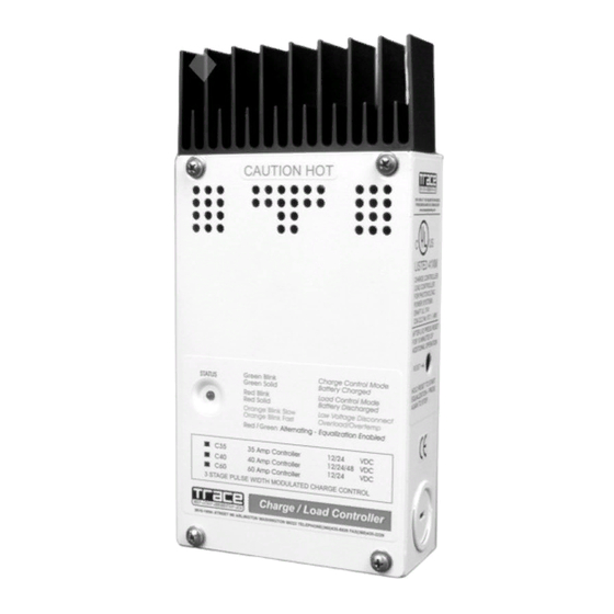
- Page 1 All manuals and user guides at all-guides.com ™ C-Series Multifunction DC Controllers Installation and Operation Guide...
- Page 2 All manuals and user guides at all-guides.com...
- Page 3 All manuals and user guides at all-guides.com C-Series Multifunction DC Controllers Table of Contents...
- Page 4 All manuals and user guides at all-guides.com Table of Contents (Continued)
-
Page 5: Important Safety Instructions
All manuals and user guides at all-guides.com IMPORTANT SAFETY INSTRUCTIONS WARNING AVERTISSEMENT CAUTION ATTENTION NOTE NOTE · · · · · · · SAVE THESE INSTRUCTIONS ! -
Page 6: Battery Safety Information
All manuals and user guides at all-guides.com BATTERY SAFETY INFORMATION · · · · · · · · · · · · · · · ·... - Page 7 All manuals and user guides at all-guides.com 1.0 INTRODUCTION Introduction · · · · · · · · · · ·...
-
Page 8: Operating Modes
All manuals and user guides at all-guides.com 1.0 INTRODUCTION Operating Modes Photovoltaic Charge Control Mode Configuring the C–Series... -
Page 9: Automatic Pv Array Night Disconnect
All manuals and user guides at all-guides.com 1.0 INTRODUCTION Automatic PV Array Night Disconnect Diversion Control Mode Three-Stage Battery Charging Configuring the C–Series... - Page 10 All manuals and user guides at all-guides.com 1.0 INTRODUCTION DC Load Control Mode C-Series DC Load Battery Controller Configuring the C-Series Attach sticker over potentiometers for Load Control Settings...
- Page 11 All manuals and user guides at all-guides.com 2.0 FEATURES Features Over-Temperature Protection Electronic Over-Current Protection...
-
Page 12: Battery Temperature Compensation
All manuals and user guides at all-guides.com 2.0 FEATURES Battery Temperature Compensation s t l ° / s t l ° / s t l ° / s t l ° / s t l ° / s t l °... -
Page 13: Led Status Indicator
All manuals and user guides at all-guides.com 2.0 FEATURES LED Status Indicator Green Blink Charge Control Mode STATUS Green Solid Battery Charged Red Blink Load Control Mode Red Solid Battery Discharged Orange Blink Slow Load Disconnected Orange Blink Fast Overload/Overtemp Green Alternating - Equalization Enabled 35 Amp Controller... - Page 14 All manuals and user guides at all-guides.com 2.0 FEATURES Charge Control or Diversion Control Mode Indications Load Control Indications...
- Page 15 All manuals and user guides at all-guides.com 2.0 FEATURES Equalization Mode Indication Error Mode Indication...
-
Page 16: Installation
All manuals and user guides at all-guides.com 3.0 INSTALLATION Installation Mounting... - Page 17 All manuals and user guides at all-guides.com 3.0 INSTALLATION Heatsink not included on C-35.
- Page 18 All manuals and user guides at all-guides.com 3.0 INSTALLATION Wiring User Configuration Options 12 Volt Position 24 Volt Position 12 Volt Position 48 Volt Position (C40 only) 24 Volt Position C35 and C60 Battery Positive + PV +/Load + Common Negatives –...
- Page 19 All manuals and user guides at all-guides.com 3.0 INSTALLATION Minimum Recommended Wire Size ° s i l ) y t ° s i l ) y t...
- Page 20 All manuals and user guides at all-guides.com 3.0 INSTALLATION Maximum One-way Distance and Wire Size...
- Page 21 All manuals and user guides at all-guides.com 3.0 INSTALLATION < t l u t l u c i f . t f . t f . t f . t f . t f . t f . t f .
- Page 22 All manuals and user guides at all-guides.com 3.0 INSTALLATION PV Charge Control Mode Cabling · · · · · · Battery Positive + PV Array Negative – Battery Negative – PV Array Positive +...
- Page 23 All manuals and user guides at all-guides.com 3.0 INSTALLATION PV Array CONTROLLER PV CHARGE CONTROL MODE COMMON BATTERY PV +/ NEGATIVES POSITIVE + LOAD + PV + BATTERY - Circuit Breaker PV - BATTERY + Circuit Breaker – BATTERY 3553-W01-00A...
- Page 24 All manuals and user guides at all-guides.com 3.0 INSTALLATION Diversion Control Mode Cabling · · · · · · Battery Positive + Diversion Load Diversion Load Battery Negative – Positive + Negative –...
- Page 25 All manuals and user guides at all-guides.com 3.0 INSTALLATION PV Array CONTROLLER LOAD DIVERSION MODE COMMON BATTERY PV +/ NEGATIVES POSITIVE + LOAD + BATTERY - DIVERSION LOAD BATTERY + Circuit Breaker PV + – Circuit Breaker BATTERY PV - 3553-W02-00A...
- Page 26 All manuals and user guides at all-guides.com 3.0 INSTALLATION DC Load Control Mode Cabling · · · · Battery Positive + DC Load Positive + DC Load Negative – Battery Negative –...
- Page 27 All manuals and user guides at all-guides.com 3.0 INSTALLATION CONTROLLER DC LOAD CONTROL MODE COMMON BATTERY PV +/ NEGATIVES POSITIVE + LOAD + BATTERY - LOAD - DC LOAD LOAD + Circuit Breaker BATTERY + Circuit Breaker – BATTERY 3553-W03-00A...
- Page 28 All manuals and user guides at all-guides.com 3.0 INSTALLATION Grounding...
- Page 29 All manuals and user guides at all-guides.com 3.0 INSTALLATION Configuring the C-Series s t l s t l z i l z i l z i l...
- Page 30 All manuals and user guides at all-guides.com 3.0 INSTALLATION NICAD SETTING SELECTION RESISTOR EQ/LVR JUMPER CHARGE/LOAD CONTROL JUMPER RESET SWITCH SYSTEM VOLTAGE JUMPER...
-
Page 31: Operating Mode
All manuals and user guides at all-guides.com 3.0 INSTALLATION Automatic/Manual Battery Equalization (EQ) and Low Voltage Reconnect (LVR) manual equalization manual reconnect 12 Volt Position 24 Volt Position 12 Volt Position 48 Volt Position 24 Volt Position C35 and C60 Operating Mode Reset Switch... - Page 32 All manuals and user guides at all-guides.com 3.0 INSTALLATION Voltage 12 Volt Position 24 Volt Position 12 Volt Position 48 Volt Position 24 Volt Position C35 and C60...
- Page 33 All manuals and user guides at all-guides.com 3.0 INSTALLATION Adjusting the C-Series Setting Voltage Parameters Three-Stage Battery Charging Process Charge/Diversion Control Mode...
- Page 34 All manuals and user guides at all-guides.com 3.0 INSTALLATION Testpoints for Voltage Settings TESTPOINTS for DC multimeter (center legs of potentiometer) Connect the negative lead of DVM to the COMMON NEGATIVE terminal DC Load Control Load Control Mode (sticker)
- Page 35 All manuals and user guides at all-guides.com 3.0 INSTALLATION Equalization Auto Equalize Manual Equalize Manual Equalize Jumper Manual Equalize Switch Setting (when in Manual mode) R46–Cut for NiCad applications...
-
Page 36: Manual Equalization
All manuals and user guides at all-guides.com 3.0 INSTALLATION Manual Equalization Front Panel LED Reset Switch Access (flashes red/green during Equalization) -
Page 37: Automatic Equalization
All manuals and user guides at all-guides.com 3.0 INSTALLATION Automatic Equalization Auto Equalize Manual Equalize Manual Equalize Jumper Manual Equalize/Reset Switch Setting... -
Page 38: Temperature Compensation
All manuals and user guides at all-guides.com 3.0 INSTALLATION Temperature Compensation s t l ° / s t l ° / s t l ° / s t l ° / s t l ° / s t l ° /... - Page 39 All manuals and user guides at all-guides.com 3.0 INSTALLATION Setting LVR and LVD (Load Control Mode) Subtract the proper voltages from the values printed on the circuit board, if the sticker is missing...
- Page 40 All manuals and user guides at all-guides.com 3.0 INSTALLATION Setting Diversion Control Mode > > > ) - ( > > > > > >...
- Page 41 All manuals and user guides at all-guides.com 4.0 OPTIONS C-Series LCD Meter Displays · · · · · · Actual Battery Watts (volts x Voltage amps) 01.5 0019 13.1 00004.3 00013.2 Totalizing Amps: Supply or Load resets to zero Current (amps) at battery or load disconnect Resettable amp-...
- Page 42 All manuals and user guides at all-guides.com 4.0 OPTIONS Installing the DVM/C40 · · · · Remove LED (pull out) Install Yellow DVM/C40 Cable...
- Page 43 All manuals and user guides at all-guides.com 4.0 OPTIONS Mounting the CM/R...
-
Page 44: Operation
All manuals and user guides at all-guides.com 5.0 OPERATION Three-Stage Battery Charging Bulk Stage Absorption Stage Float Stage Charging Bulk Volts Setting Started Float Volts Setting Absorption Time DC Voltage Increasing Voltage Constant Voltage Reduced Voltage 0 volts Max Amps Constant Current Reducing Current Reduced Current... - Page 45 All manuals and user guides at all-guides.com 5.0 OPERATION > > > ) - ( > > > > > > z i l t l u t i s t l u , e l i t n n i l t l u t l u t l u...
- Page 46 All manuals and user guides at all-guides.com 5.0 OPERATION Equalization (Non-Sealed Batteries Only)
-
Page 47: Automotive Batteries
All manuals and user guides at all-guides.com 6.0 BATTERIES Batteries Automotive Batteries Maintenance-Free Batteries Deep-Cycle Batteries... -
Page 48: Sealed Batteries
All manuals and user guides at all-guides.com 6.0 BATTERIES Sealed Batteries NiCad and NiFe Batteries Battery Sizing... -
Page 49: Diversion Loads
All manuals and user guides at all-guides.com 7.0 DIVERSION LOADS Charge Controller Load Controller Diversion Charge Controller... -
Page 50: Diversion Load Types
All manuals and user guides at all-guides.com 7.0 DIVERSION LOADS Diversion Load Types... - Page 51 All manuals and user guides at all-guides.com 7.0 DIVERSION LOADS...
-
Page 52: Specifications
All manuals and user guides at all-guides.com 8.0 SPECIFICATIONS a t l t i u a t l t i u ° t i u t n i y l t t n i y l t t n i y l t a t l s t l... -
Page 53: Service Information
All manuals and user guides at all-guides.com 9.0 SERVICE INFORMATION Service Information visit our website at: www.traceengineering.com or e-mail us at: traceengineering.com... -
Page 54: Limited Warranty
Xantrex agrees to supply all parts and labor to repair or replace defects covered by this warranty with parts or products of original or improved design, at the company's option. Xantrex also reserves the right to improve the design of its products without obligation to modify or upgrade those previously manufactured. - Page 55 All manuals and user guides at all-guides.com...
- Page 56 All manuals and user guides at all-guides.com 5916 - 195th Street N.E., Arlington, WA 98223 Phone: 360/435.8826 Fax: 360/435.2229 visit our website at: www.traceengineering.com...
Need help?
Do you have a question about the Trace C Series and is the answer not in the manual?
Questions and answers