Sign In
Upload
Manuals
Brands
Xantrex Manuals
Controller
Trace C40
Xantrex Trace C40 Manuals
Manuals and User Guides for Xantrex Trace C40. We have
3
Xantrex Trace C40 manuals available for free PDF download: Owner's Manual, Installation And Operation Manual
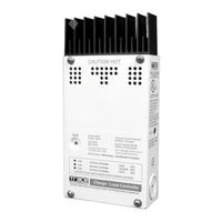
Xantrex Trace C40 Owner's Manual (114 pages)
C-Series Multifunction DC Controller
Brand:
Xantrex
| Category:
Controller
| Size: 1 MB
Table of Contents
Contact Information
4
About this Guide
5
Abbreviations and Acronyms
7
Related Information
7
General Safety Instructions
9
Important Safety Instructions
9
Battery Safety Information
10
Table of Contents
13
Introduction
21
Features
22
Figure 1-1 C-Series Multifunction DC Charge Controllers
22
Operating Modes
23
Charge Control Mode
24
Three-Stage Battery Charging
24
Figure 1-2 3-Stage Battery Charging Process
25
Battery Temperature Compensation
26
Manual or Auto Equalization Charge
26
Load Control Mode
26
Controller Functions
27
Photovoltaic Charge Controller
27
Figure 1-3 PV Charge Controller
27
Automatic PV Array Night Disconnect
28
Diversion Controller
28
Diversion Loads
29
Figure 1-4 Diversion Controller
29
Load Controller
30
Figure 1-5 Load Controller
31
Low Voltage Disconnect
31
Low Voltage Reconnect
31
Optional Accessories
32
Figure 1-6 Decal Displaying Load Control Voltage Settings
32
Figure 1-7 Optional Accessories - CM/R, CM, and BTS
32
Installation
33
Pre-Installation
34
Removing the Top Cover
34
Removing Knockouts
34
Figure 2-1 Removing the Front Cover
34
Figure 2-2 C-Series Dimensions and Knockout Locations
35
Mounting the Controller
36
Configuring the C-Series Controller
38
Jumper Settings
38
Figure 2-4 Jumper Positions
38
Figure 2-5 Circuit Board Components
39
Table 2-1 Factory Default Settings for C-Series Controllers
39
Operating Mode Jumper
40
Voltage Jumper
40
Figure 2-6 Mode of Operation Jumper
40
Figure 2-7 Voltage Selection Jumper
40
Automatic/Manual Battery Equalization (EQ) and Low Voltage Reconnect (LVR) Jumper
41
Figure 2-8 EQ/LVR Jumper and Reset Switch
41
Chapter 2 Contains Information and Procedures to Install
42
Adjusting the C-Series Voltage Settings
42
Figure 2-9 Bulk and Float Charge Potentiometers (Pots)
42
Setting Voltage Parameters for Charge Control Mode
42
Control Mode
43
Figure 2-10 Bulk and Float Charge Settings for Charge/Diversion
43
Figure 2-11 Potentiometers with Decal for LVR and LVD Settings
44
Setting Voltage Parameters for Load Control Mode
44
Figure 2-12 LVR and LVD Settings for Load Control Mode
45
Figure 2-13 R46 Resistor Location
46
Setting Voltage Parameters Diversion Control Mode
46
Setting Voltage Parameters for Alkaline Batteries
46
Figure 2-14 Voltage Settings with R46 Resistor Clipped
47
Using a Digital Voltmeter to Adjust Voltage Settings
48
Figure 2-15 Test Points for Adjusting Voltage Using a DVM
49
Equalization Charging
50
Figure 2-16 Manual Equalization Settings
50
Figure 2-17 Front Panel LED and Reset Switch Location
51
Manual Equalization
51
Automatic Equalization
52
Figure 2-18 Auto Equalization Settings
52
Figure 2-19 Terminating the Equalization Charge
53
Temperature Compensation
53
Terminating the Equalization Process
53
Automatic Battery Temperature Compensation
54
Temperature Compensation Based on Battery Type
54
Table 2-2 Variances in Charging Voltage Based on Battery Temperature
55
Manual Battery Temperature Compensation
56
Figure 2-20 Grounding the
57
Grounding
57
DC Terminal Connector Locations
58
Wiring
58
Current Rating
59
Figure 2-21 DC Connection Terminals
59
Terminal Torque Requirements
59
Wire Size and Over-Current Protection Requirements
59
Figure 2-22 AWG Wire Gauge Reference Chart
60
Minimum Recommended Wire Gauge
60
Surge Protection
60
Over-Current Protection
61
Table 2-3 Minimum Wire Size
61
Long-Distance Wire Runs
62
Maximum One-Way Distance and Wire Size
62
Table 2-4 One-Way Wire Distance and Wire Size
63
PV Charge Control Mode Wiring
64
Figure 2-23 PV Charge Control Mode Wiring
65
Diversion Control Mode Wiring
66
Figure 2-24 Diversion Control Mode Wiring
67
DC Load Control Mode Wiring
68
Figure 2-25 Load Control Mode Wiring
69
Figure 2-26 Installing a Digital Display
70
Installing a Digital Display
70
Installing Optional Accessories
70
Figure 2-27 Installing the BTS
71
Installing the Battery Temperature Sensor
71
Figure 2-28 Re-Installing the CM Faceplate
72
Reinstalling the Faceplate
72
Operation
73
Chapter 3 Contains Information about the Operation of a
74
Basic Operation
74
Figure 3-1 C-Series Status LED and Reset Button Location
74
LED Status Indicator
75
Figure 3-2 C-Series Front Panel Label
75
Charge Control or Diversion Control
76
Charge Control or Diversion Control Indications (Green)
76
Table 3-1 Battery Voltage LED Indicators
76
Blinking Green
77
Solid Green
77
Blinking Red
78
Equalization Mode Indication (Red/Green)
78
Load Control Indications (Red)
78
Solid Red
78
Error Mode Indication (Orange)
79
Over-Current Condition
79
Over-Temperature Condition
79
Low-Voltage Disconnect Condition
80
Reconnecting to Loads
80
Reset Switch
81
Figure 3-3 Reset Switch
81
Troubleshooting
83
PV Charge Control Troubleshooting
84
Table 4-1 PV Charge Control Problems
84
Diversion Control Troubleshooting
86
Table 4-2 Diversion Control Problems
86
Load Control Troubleshooting
88
Table 4-3 Load Control Problems
88
Specifications
89
Electrical Specifications
90
Table A-1 Electrical Specifications
90
Features and Options Specifications
91
Table A-2 Features and Options Specifications
91
Environmental Specifications
92
Table A-3 Environmental Specifications
92
Battery Types
94
Automotive Batteries
94
Maintenance-Free Batteries
94
Deep-Cycle Batteries
94
Sealed Batteries
95
Nicad and Nife Batteries
96
Battery Sizing
96
Equalization Charging
97
Equalization Setpoints (Non-Sealed Batteries Only)
99
Table B-1 Typical Bulk and Float Setpoints for Batteries
99
Diversion Loads
101
Diversion Load Types
102
Table C-1 Power Dissipation
102
Warranty and Product Information
105
Warranty
105
Disclaimer
106
Return Material Authorization Policy
107
Return Procedure
108
Out of Warranty Service
108
Information about Your System
109
Index
111
Advertisement
Xantrex Trace C40 Installation And Operation Manual (57 pages)
C-series DC controllers
Brand:
Xantrex
| Category:
Controller
| Size: 6 MB
Table of Contents
Important Safety Instructions
5
Battery Safety Information
6
Operating Modes
8
Automatic PV Array Night Disconnect
9
Over Temperature Protection
11
Battery Temperature Compensation
12
LED Status Indicator
13
Equalization Mode Indication
15
Installation
16
Operating Mode
31
Reset Switch
31
Manual Equalization
36
Automatic Equalization
37
Temperature Compensation
38
Operation
44
Three-Stage Battery Charging
44
Automotive Batteries
47
Maintenance-Free Batteries
47
Battery Sizing
48
Diversion Loads
49
Diversion Load Types
50
Specifications
52
Service Information
53
Limited Warranty
54
Xantrex Trace C40 Installation And Operation Manual (57 pages)
Multifunction DC Controllers
Brand:
Xantrex
| Category:
Controller
| Size: 6 MB
Table of Contents
Important Safety Instructions
5
Battery Safety Information
6
Operating Modes
8
Automatic PV Array Night Disconnect
9
Battery Temperature Compensation
12
LED Status Indicator
13
Installation
16
Operating Mode
31
Reset Switch
31
Manual Equalization
36
Automatic Equalization
37
Temperature Compensation
38
Operation
44
Three-Stage Battery Charging
44
Automotive Batteries
47
Sealed Batteries
48
Battery Sizing
48
Diversion Loads
49
Diversion Load Types
50
Specifications
52
Service Information
53
Limited Warranty
54
Advertisement
Advertisement
Related Products
Xantrex Trace C35
Xantrex Trace C60
Xantrex Trace C Series
Xantrex C40R/100 Remote
Xantrex C40R/50 Remote
Xantrex Communications gateway
Xantrex C12
Xantrex Trace DR1512
Xantrex Trace DR2412
Xantrex Trace DR2424
Xantrex Categories
Inverter
Power Supply
Battery Charger
Power Pack
Controller
More Xantrex Manuals
Login
Sign In
OR
Sign in with Facebook
Sign in with Google
Upload manual
Upload from disk
Upload from URL