Table of Contents
Advertisement
Advertisement
Table of Contents
Troubleshooting

Related Manuals for Xantrex XW-MPPT60-150


Summary of Contents for Xantrex XW-MPPT60-150
- Page 1 XW-MPPT60-150 Owner’s Manual XW Solar Charge Controller...
- Page 3 XW Solar Charge Controller Owner’s Guide...
- Page 4 About Xantrex Xantrex Technology Inc. is a world-leading supplier of advanced power electronics and controls with products ranging from small mobile units to utility-scale systems for wind, solar, batteries, fuel cells, microturbines, and backup power applications in both grid-connected and stand-alone systems. Xantrex products include inverters, battery chargers, programmable power supplies, and variable speed drives that convert, supply, control, clean, and distribute electrical power.
-
Page 5: About This Guide
About This Guide Purpose The purpose of this Guide is to provide explanations and procedures for installing, configuring, operating, and troubleshooting the XW Solar Charge Controller (XW SCC). Scope This Guide provides safety guidelines, detailed planning and setup information, procedures for installing the unit, as well as information about operating and troubleshooting the unit. - Page 6 These notes describe things which are important for you to know, but not as serious as a caution or warning. Related Information You can find more information about Xantrex Technology Inc. as well as its products and services at www.xantrex.com. 975-0400-01-01...
-
Page 7: Important Safety Instructions
Important Safety Instructions WARNING This manual contains important safety instructions that should be followed during the installation and maintenance of this product. Be sure to read, understand, and save these safety instructions. General Safety Instructions • All electrical work must be done in accordance with local, national, and/or international electrical codes. - Page 8 Safety • Remove all jewelry before working with batteries. • Never work alone. Have someone assist you with the installation or be close enough to come to your aid when working with batteries. • Always use proper lifting techniques when handling batteries. •...
-
Page 9: Table Of Contents
Contents Important Safety Instructions - - - - - - - - - - - - - - - - - - - - - - - - - - - - - - - - - - - - - - - - - - - -v 1 Introduction Features - - - - - - - - - - - - - - - - - - - - - - - - - - - - - - - - - - - - - - - - - - - - - - - - - - - - - - - - - - - - - 1–2 Maximum Power Point Tracking - - - - - - - - - - - - - - - - - - - - - - - - - - - - - - - - - - - - - - - - - - - - 1–3... - Page 10 Contents Maximum One-way Distance and Wire Size - - - - - - - - - - - - - - - - - - - - - - - - - - - - - -2–12 Connecting the XW SCC - - - - - - - - - - - - - - - - - - - - - - - - - - - - - - - - - - - - - - - - - - - - - -2–13 Connecting Multiple Units - - - - - - - - - - - - - - - - - - - - - - - - - - - - - - - - - - - - - - - - - - - - - - - -2–15 Aux Output Connections - - - - - - - - - - - - - - - - - - - - - - - - - - - - - - - - - - - - - - - - - - - - - - - - -2–16 Disconnecting the Charge Controller - - - - - - - - - - - - - - - - - - - - - - - - - - - - - - - - - - - - - - - - -2–17...
- Page 11 Contents Daily Logs - - - - - - - - - - - - - - - - - - - - - - - - - - - - - - - - - - - - - - - - - - - - - - - - - - - - 4–12 Monthly Logs - - - - - - - - - - - - - - - - - - - - - - - - - - - - - - - - - - - - - - - - - - - - - - - - - - 4–12 Battery Equalization - - - - - - - - - - - - - - - - - - - - - - - - - - - - - - - - - - - - - - - - - - - - - - - - - - - 4–13 5 Troubleshooting...
-
Page 13: Introduction
Introduction Chapter 1 describes features and functions of the XW Solar Charge Controller. For information on: See: “Features” page 1–2 “Maximum Power Point Tracking” page 1–3 “Charge Controlling” page 1–4 “Auxiliary Output Functions” page 1–8 “Automatic PV Array Night Disconnect” page 1–8... -
Page 14: Features
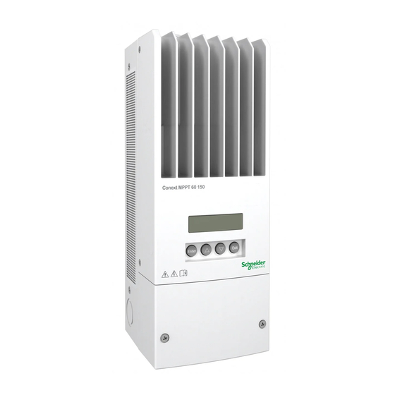
The DC source must meet the specifications listed on page A–2. The XW SCC can be installed (in single or multi-unit configurations) with a Xantrex XW Hybrid Inverter/Charger or in a stand-alone installation. Figure 1-1 XW Solar Charge Controller Standard features of the XW Solar Charge Controller include: •... -
Page 15: Maximum Power Point Tracking
Xanbus -enabled. Xanbus is a network communications protocol developed by Xantrex. The XW SCC is able to communicate its settings and activity to other Xanbus-enabled devices, such as the XW Series Inverter/Charger, the XW System Control Panel (SCP), XW Automatic Generator Start (XW- AGS), and other XW Solar Charge Controllers. -
Page 16: Charge Controlling
Introduction Charge Controlling The XW SCC can regulate PV array current at 12, 24, 36, 48 or 60 volts DC for charging batteries. It produces up to 3500 watts and 60 amps of charging current for all battery voltages except 60 volts. Figure 1-3 PV Charge Controller The XW SCC controls how the batteries are charged by the DC source (the PV array). -
Page 17: Absorption Stage
Charge Controlling Absorption Stage During the absorption stage, the XW SCC continues to deliver its maximum available current output until the battery voltage reaches the absorption voltage setting. The XW SCC then operates in constant voltage mode, holding the battery voltage at the absorption voltage setting for a pre-set time limit (the default time limit is three hours). -
Page 18: Two-Stage Battery Charging
Introduction Two-Stage Battery Charging The two-stage charging process includes the bulk and absorption stages, but uses a “No Float” stage instead of “Float.” The relationship between charging current and battery voltage during the two-stage charging process is shown in Figure 1-5. No Float Stage During the No Float stage the XW SCC does not produce any charge current. -
Page 19: Battery Temperature Compensation
Charge Controlling Battery Temperature Compensation The Battery Temperature Sensor (BTS) automatically adjusts the charging process of the XW SCC. With the BTS installed, the XW SCC increases or decreases the battery charging voltage depending on the temperature of the battery to optimize the charge to the battery and to protect it from over-charge or damage. -
Page 20: Auxiliary Output Functions
Introduction Auxiliary Output Functions The XW SCC has a configurable auxiliary output (producing 5 to 13 volts and up to 200 milliamps) to drive a relay for load control or to turn on devices such as vent fans or indicator alarms. The auxiliary output can be configured to perform only one function at a time. -
Page 21: Installation
Installation Chapter 2 contains information and procedures to install the XW Solar Charge Controller. Before installing the XW SCC, read this entire chapter. Depending on your installation, you may need to perform certain installation stages in a different order than the order presented in this chapter. -
Page 22: Pv Array Requirements
Installation PV Array Requirements Note: The following information provides only general guidelines. The installation and rated performance of your PV array is subject to inspection and approval by the authority having jurisdiction. Each XW Solar Charge Controller (XW SCC) must be connected to its own PV array. -
Page 23: Mounting
Installation procedures will vary according to your specific application. For special applications, consult a qualified electrician or your Xantrex Certified Dealer. If installing the XW SCC as part of an XW System, see the XW Power System Installation Guide for additional information. - Page 24 Installation Table 2-2 Minimum Clearance Requirements Location Minimum Clearance Above 6 inches (150 mm). When units are mounted in a vertical stack, the topmost unit must maintain the minimum clearance to the nearest surface. Note: Minimum clearances can be ignored when mounting two units on the side of the XW Power Distribution Panel (part number 865-1015).
-
Page 25: Removing The Wiring Compartment Cover
Mounting Removing the Wiring Compartment Cover Before mounting, remove the wiring compartment cover to access the mounting holes and the wiring terminals. The wiring compartment cover is secured with two Phillips #8-32 × 2 ½-inch (63.5 mm) screws on the front cover of the unit. See Figure 2-2. - Page 26 Installation Keyhole slot for wall mounting (2 7/8) 323 (12 3/4) 280 (11) Additional mounting holes 368 (14 1/2) Ø 6.35 (1/4) 60 (2 3/8) 53 (2 1/16) 14 (9/16) (4 5/8) 26.5 (5 3/4) (5 7/16) All measurements in mm (in.) Figure 2-3 Dimensions and Knockout Locations Single knockouts are intended for BTS and network cables...
-
Page 27: Mounting The Charge Controller
Grounding Mounting the Charge Controller The XW SCC is vertically mounted using three #10 × ½-inch or #12 × ½-inch (12.5 mm) pan-head screws. To mount the XW SCC: 1. Remove the wiring compartment cover. 2. Mark the location of the keyhole slot on the wall. 3. -
Page 28: Internal Ground Fault Protection
Installation Internal Ground Fault Protection The XW SCC has a PV ground fault protection (PV-GFP) fuse (600 V, 1 A) and a PV negative-ground jumper located inside the wiring compartment. These provide a negative ground bond and ground-fault protection for negative grounded PV array systems common in North American installations. -
Page 29: Disabling Ground Fault Protection For Negative Grounded And Ungrounded Arrays
Grounding Disabling Ground Fault Protection for Negative Grounded and Ungrounded Arrays To install the XW SCC in a system where an external negative-ground bond is required or where the PV array must not be grounded, the XW SCC internal PV- GFP circuit and ground bond must be disabled. -
Page 30: Wiring
Installation Wiring Important: Installations must meet all local electrical codes.This equipment should only be installed by a qualified electrician or a Certified Renewable Energy System Installer. WARNING: Shock hazard Disconnect PV and battery circuits before wiring. DC Terminal Connector Locations Terminal connectors for DC wiring are located inside the wiring compartment. -
Page 31: Minimum Wire Gauge
Wiring Minimum Wire Gauge For installations where the PV array output is the maximum allowable 60 A I the minimum allowable wire gauge is #6 AWG (16 mm ) copper wire with a 90 °C (194 °F) insulation rating. This wire gauge is determined by electrical code requirements regarding conduit knockout sizes, wire bending radius, and space available within the XW SCC wiring compartment. -
Page 32: Maximum One-Way Distance And Wire Size
Installation Maximum One-way Distance and Wire Size Important: Local and national electrical codes must be followed for determining additional installation requirements. Refer to Table 2-3 and find the maximum current in the left column, and the one- way distance from the PV array to the XW SCC (or the distance from the XW SCC to the battery) on the same line, then read the wire size required at the top of the column. -
Page 33: Connecting The Xw Scc
Wiring Connecting the XW SCC The following procedure is illustrated in Figure 2-9. WARNING: Shock hazard Whenever a PV array is exposed to light, a shock hazard exists at the output wires or exposed terminals. To reduce the risk of shock during installation, cover the array with an opaque (dark) material before making the connections. - Page 34 Installation Wire Size Torque Value in-lb 14–10 2.5–6 2.25 Allow some slack on the cables within the XW SCC and secure the wiring with strain reliefs or cable clamps. – BA T – – PV array disconnect Battery Do not connect the disconnect/ overcurrent battery negative to...
-
Page 35: Connecting Multiple Units
Connecting Multiple Units Connecting Multiple Units In a multiple-unit installation, each XW SCC must be connected to a separate PV array. For other multiple-unit installation considerations, see “Network Installation” on page 2–18. Important: Only one Charge Controller is to have the PV-GFP fuse installed in installations with multiple parallel XW SCCs. -
Page 36: Aux Output Connections
Installation Aux Output Connections WARNING: Shock hazard If the PV-GFP internal protection has activated, shock-hazardous voltage may appear at the AUX connector and at the battery terminals. To avoid a shock hazard, ensure that all connections made to the AUX terminals have no uninsulated wire segments and that all wiring has an insulation rating of at least 300 V. -
Page 37: Disconnecting The Charge Controller
Disconnecting the Charge Controller Disconnecting the Charge Controller WARNING: Shock hazard Ensure both the PV array and the batteries are disconnected from the XW SCC before servicing the XW SCC or the batteries. After disconnecting the batteries, the XW SCC can appear de-energized when the PV array is still connected. -
Page 38: Network Installation
XW Hybrid Inverter/Charger provides the required 15 Vdc/200 mA network power. • Network cables—Each Xanbus-enabled device is connected by a standard Ethernet (CAT 5 or CAT 5e) cable, available from Xantrex or any computer supply store. CAUTION: Equipment damage Do not use crossover cable. -
Page 39: Ordering Network Components
Table 2-4 provides a partial list of network components and part numbers. Cables are available in standard lengths from 3 feet (0.9 m) to 75 feet (22 m). Call your dealer or visit the Outlet Store at www.xantrex.com to purchase cables and other network components. -
Page 40: Connecting Network Cable Between Multiple Units
Installation Connecting Network Cable Between Multiple Units WARNING: Shock hazard Do not route the network cables in the same conduit or panel as the DC input/output cables. WARNING: Shock hazard Before opening the XW SCC wiring compartment, ensure the PV array and batteries are disconnected. -
Page 41: Installing The Battery Temperature Sensor
If the sensor cable is damaged and the wires are shorted, the XW SCC displays an over-temperature fault message. If the BTS wires have been cut, the XW SCC assumes that the BTS is not connected. Replacement Battery Temperature Sensors are available from Xantrex (replacement part number 808-0232-02). To install the BTS: 1. - Page 42 BTS plug into the BTS port. See Figure 2-15. Important: The BTS cable must not pass through the same conduit used for PV wiring and battery cables. 5. Replace the XW SCC wiring compartment cover. xantrex Insert the BTS plug into – – Port the XW SCC BTS port.
-
Page 43: Commissioning
Commissioning Commissioning During commissioning, the XW SCC prompts you to enter important system information such as the nominal battery voltage, battery type, and battery bank capacity. Ensure you have this system information prior to commissioning. In systems where an XW System Control Panel (SCP) is present, the SCP is intended to be the configuration interface, so the prompt screens are suppressed. -
Page 44: Commissioning A Single Unit Without A System Control Panel
Table 2-5 Startup Screens on XW SCC Front Panel Display Display Duration Description Xantrex 5 seconds Startup message 1: XW SCC model number XW-MPPT60-150 01.00 5 seconds Startup message 2: Firmware version and build Build 0005 numbers. This screen is also available in the Device Menu for referencing during normal operation (see page 3–18). -
Page 45: Commissioning Multiple Units Without A System Control Panel
Commissioning The XW SCC starts up in sleep mode and waits for a short period to determine that the input voltage is greater than the output voltage. The LCD indicates the XW SCC mode or any error conditions that may be present (see “Viewing Operating Status”... - Page 46 Installation Note: If it is necessary to reset the XW SCC to factory default settings, checking that the device number has reverted to 00 will confirm the reset was successful. After setting the device numbers, a “Copy Config?” prompt screen appears on all of the XW SCCs.
-
Page 47: Commissioning Units Using A System Control Panel
Commissioning Commissioning Units Using a System Control Panel In systems where an XW System Control Panel (SCP) is present, the SCP is intended to be the configuration interface. For information about SCP navigation and menus, see Appendix B, “XW System Control Panel Menus”. Commissioning units using an SCP involves three separate procedures: 1. - Page 48 Installation On the Connections menu, you can configure PV In (PV input) and DC Conn (DC output, or the battery bank). If the system has only one battery bank, leave DC Conn at the default setting. The PV In setting allows you to differentiate which array is going to which XW SCC.
-
Page 49: Configuration
Configuration Chapter 3 contains information and procedures to configure the XW Solar Charge Controller. See: For information on: “Configuration Menus” page 3–3 “Configuring Battery Characteristics and page 3–5 Battery Charging” “Configuring XW SCC Input” page 3–11 “Configuring the Auxiliary Output” page 3–12 “Configuring the LCD”... -
Page 50: Configuring The Xw Scc
Configuration Configuring the XW SCC The following sections describe how to configure the XW SCC for the desired application and function. The XW SCC is configured using the four buttons on the front of the unit. Table 3-1 XW SCC buttons Button Function Enter... -
Page 51: Configuration Menus
Configuration Menus Configuration Menus The menus for setup and monitoring XW SCC performance are shown in Figure 3-1 and Figure 3-2. FAULTS AND Not a configuration menu. See page 4–8. WARNINGS MENU View and reset data logs and monitor XW SCC HISTORY MENU performance. - Page 52 Configuration Figure 3-2 Complete Configuration Menus 3–4 975-0400-01-01...
-
Page 53: Configuring Battery Characteristics And Battery Charging
Configuring Battery Characteristics and Battery Charging Configuring Battery Characteristics and Battery Charging On the Battery Menu you can: • Start battery equalization • Configure your battery type, voltage and amp-hour capacity • Configure a custom battery type by adjusting settings for each battery charge stage and fine-tuning temperature-compensated charging •... - Page 54 Configuration Table 3-2 Battery Menu Values Setting Values Default Description Equalize Activate/Stop Activate Enables or disables Battery Activate Equalization. If the Battery Type is set to GEL or AGM, this setting is disabled. Equalization 0–365 d(ays) Sets a reminder that notifies you Reminder 0d when the battery needs equalizing.
- Page 55 Configuring Battery Characteristics and Battery Charging Table 3-2 Battery Menu Values Setting Values Default Description Max Absorb Time 120–360 min 180 min Sets the maximum time spent at 180min a constant voltage (the setting for Absorption voltage) during the absorption stage. This setting does not control the duration of the entire Absorption stage.
-
Page 56: Setting A Custom Battery Type
Configuration Setting a Custom Battery Type CAUTION: Equipment damage To avoid damaging your batteries during charging or equalization, consult your battery manufacturer and associated documentation before setting a custom battery type. The Custom Battery menu allows you to adjust charging and equalization voltage for batteries whose specifications fall outside of the default settings for the battery types the XW SCC offers. - Page 57 Configuring Battery Characteristics and Battery Charging Table 3-3 Custom Battery Menu Values Setting Values Default Description Float Voltage 12V: 10.0–16.0V 13.5V Sets the float voltage for a 13.5V 24V: 20.0–32.0V 27.0V custom battery type. 36V: 30.0–48.0V 40.5V 48V: 40.0–64.0V 54.0V 60V: 50.0–72.0V 67.5V Batt Temp Comp...
-
Page 58: Battery Temperature Compensation
Configuration Battery Temperature Compensation When battery charging voltages are compensated based on temperature, the charge voltage will vary depending on the temperature around the batteries. Temperature compensation can be accomplished automatically by using a BTS. The BTS attaches directly to the side of one of the batteries in the bank and provides precise battery temperature information. -
Page 59: Configuring Xw Scc Input
Configuring XW SCC Input Configuring XW SCC Input On the Input Menu you can disable automatic maximum power point tracking and configure the reference voltage level the XW SCC operates from. Configuring the reference voltage is not required for normal operation, but can be useful for non- PV applications or for testing purposes. -
Page 60: Configuring The Auxiliary Output
Configuration Configuring the Auxiliary Output The Aux Menu allows you to enable and configure the auxiliary output. The auxiliary output provides between 5 and 13 volts DC (configurable) and up to 200 milliamps to power a relay, indicator light, vent fan, or alarm. The Aux Menu is an Advanced Menu item. - Page 61 Configuring the Auxiliary Output Table 3-5 Aux Menu Values Setting Values Default Description Trigger Source Low Batt Selects the desired condition to Low Batt Voltage Voltage, Batt activate the Aux Output. Hi Batt Voltage, Voltage Hi Array Voltage, Low Batt Temp, Hi Batt Temp, Hi Heat Sink Temp, Fault...
-
Page 62: Trigger Source Descriptions
Configuration Important: If the selected trigger source is Low Batt Voltage or Hi Batt Voltage, changing the nominal battery voltage setting will reset the Trigger Voltage Level and Clear Voltage Level settings to their default values. Trigger Source Descriptions Low Batt Voltage Activates the auxiliary output when the battery voltage falls below the trigger setting for the trigger delay time. -
Page 63: Trigger Source Configurable Ranges
Configuring the Auxiliary Output Hi Batt Temp Activates the auxiliary output when the battery temperature rises above the trigger setting for the trigger delay time. Deactivates the auxiliary output when the battery temperature falls below the clear setting for the clear delay time. -
Page 64: Configuring The Lcd
Configuration Configuring the LCD On the Display Menu you can adjust the screen settings for the LCD, define Custom Screens, and select to view Basic or Advanced menus. DISPLAY MENU Enter Exit Contrast Brightness Backlight Hold 5sec Display Hold 30 sec Enter Custom Screen 1 Scrn 1 ln 1 text... - Page 65 Configuring the LCD Table 3-7 Display Menu Values Setting Values Default Description Contrast 1–9 Line 1: Adjusts screen contrast. Brightness 1–9 Line 2: Adjusts backlight brightness. Backlight Hold 0, 5sec, 5 sec Adjusts how long the backlight stays on 5sec 10sec, after the last key press.
-
Page 66: Device Menu
Configuration Device Menu On the Device Menu you can change the operating mode of the XW SCC and view the XW SCC’s device number. Both these activities may be necessary for service or diagnostics, or when adding another Xanbus-enabled device to the system. - Page 67 Device Menu Table 3-8 Device Menu Values Setting Values Default Description Mode Operating, Operating Operating is the normal mode for the Operating Standby, unit. Hibernate Standby disables the output by disconnecting the main power circuit from the battery. The unit cannot charge.
-
Page 68: Resetting To Factory Defaults
Configuration Resetting to Factory Defaults On the Reset Menu you can restore factory default settings. The Reset Menu is an advanced menu item. To display the Reset Menu, go to the Display Menu, view the Display Mode screen and select Advanced. RESET MENU Enter Exit... -
Page 69: Operation
Operation Chapter 4 contains information about the operation of the XW Solar Charge Controller. For Information on: See: “Viewing Operating Status” page 4–2 “Monitoring XW SCC Operation” page 4–7 “Battery Equalization” page 4–13... -
Page 70: Viewing Operating Status
Operation Viewing Operating Status The XW SCC has four buttons and a 2-line, 16 character liquid crystal display (LCD) for configuration and displaying system information and operating status. • When in Charge Control mode the LCD shows the output power, voltage and current (and additional information as shown in Figure 4-1 on page 4–2). -
Page 71: Normal Operation
Viewing Operating Status Normal Operation All readings on the XW SCC LCD are refreshed every two seconds. A default top-level display is available at all times (see Table 4-1). The additional screens can be displayed by pressing the down arrow or up arrow button. You can also configure the XW SCC to scroll through each operating screen in sequence (changing every four seconds). - Page 72 Operation Table 4-3 Other Operation Screens Display Description System 4500Ah Accumulated amp-hours and kilowatt-hours produced by Today 247.5kWh multiple XW SCCs today. This screen appears only when multiple XW SCCs are installed in a network. Input 3002W Measured input power, voltage, and current. 100.3V 30.0A Today 356.0Ah...
-
Page 73: Charge Stages
Viewing Operating Status Charge Stages The charge stages displayed on the LCD are described in Table 4-4. Table 4-4 Charge Stages Text Description Bulk Batteries are charging at the maximum current output of the DC source. If the Charge Controller shuts down because of low input voltage, the unit restarts in bulk mode. -
Page 74: Dynamic Text
Operation Dynamic Text The text that appears on the second line of the charge mode screen is described in Table 4-5. Table 4-5 Dynamic Text Text Appears When... Charging The charge stage is Bulk, Absorb, or Float. Two-stage charging is selected and the Charge Controller is in the No Charging Float stage. -
Page 75: Monitoring Xw Scc Operation
Monitoring XW SCC Operation Monitoring XW SCC Operation During operation, you may want to view Active Fault and Warning messages and logged power production data. This information is available on the configuration and history menus. To view configuration and history menus, press Enter from any Operating screen. FAULTS AND See page 4–8. -
Page 76: Viewing Active Faults And Warnings
Operation Viewing Active Faults and Warnings You can view active faults and warnings from the Faults and Warnings Menu. Note: The Faults and Warnings menu is visible only when the XW SCC has one or more active faults or warnings. Warning messages indicate a problem that could affect normal operation. - Page 77 Monitoring XW SCC Operation Press the down arrow to select the “Aux Output Ovld” fault, then Enter to clear it. FAULTS AND WARNINGS MENU Enter Exit Enter Active Faults Batt Under Volt and Warning Menu Exit Clear Fault Batt Under Volt Figure 4-3 Faults and Warnings Menu Table 4-6 Fault and Warning Messages Display...
- Page 78 Operation Table 4-6 Fault and Warning Messages Display Description Batt Under Volt The Batt Under Volt (Battery Under Voltage) Fault appears when the battery voltage falls to the nominal battery voltage, minus 4 V per 12 V (for example, below 32 V in a 48 V system) for 1 second.
-
Page 79: Daily Logs
Monitoring XW SCC Operation Viewing Logged System Data The XW SCC stores accumulated operating data for viewing on the History menu. You can also reset some of the logged data on the History menu. On the History Menu you can view logs for daily, monthly, or lifetime power production. -
Page 80: Daily Logs
Operation Daily Logs To view the daily logs stored in memory, press Enter from the Daily Logs screen, then press the down arrow button to view each log, starting with the most recent. On the log screen, the current day is “Today–00,” yesterday is “Today–01,” and so on. -
Page 81: Battery Equalization
Battery Equalization Battery Equalization Equalization charging is the process of deliberately charging a battery (or battery bank) at a high voltage for a set period of time. Equalize charging remixes the electrolyte, helps to remove sulfate buildup on the battery plates, and balances the charge of individual cells. - Page 82 Operation To manually begin battery equalization: 1. From the Battery Menu screen, press Enter. 2. On the Equalize screen, select Activate. If the battery is in the float or no float stage, the XW SCC goes back to the bulk stage and goes through a full charge cycle before entering the Equalization stage.
-
Page 83: Troubleshooting
Troubleshooting Chapter 5 contains information about identifying and resolving possible problems with systems using a XW Solar Charge Controller. -
Page 84: Pv Charge Control Troubleshooting
Troubleshooting PV Charge Control Troubleshooting Table 5-1 lists possible problems that may arise when using the XW Solar Charge Controller. Table 5-1 PV Charge Control Problems Problem Possible Cause Solution The LCD shows “Low PV wires are connected in Verify PV polarity relative Light”... -
Page 85: Replacing The Ground Fault Protection Fuse
Replacing the Ground Fault Protection Fuse Table 5-1 PV Charge Control Problems Problem Possible Cause Solution The LCD shows “Ground A ground fault has caused See “Replacing the Ground Fault” and the unit has the ground fault protection Fault Protection Fuse”. stopped operating. - Page 86 5–4...
-
Page 87: Electrical Specifications
Specifications Appendix A provides the specifications for the XW Solar Charge Controller. For information on: See: “Electrical Specifications” page A–2 “Default Battery Charging Settings” page A–2 “Mechanical Specifications” page A–3 “Output Power Versus Ambient page A–3 Temperature” “Optional Accessories” page A–4 “Regulatory Approvals”... -
Page 88: Electrical Specifications
Specifications Electrical Specifications Maximum PV Array Voltage (Operating) 140 Vdc Maximum PV Array Open Circuit Voltage 150 Vdc Array Short Circuit Current 60 Adc maximum Nominal Battery Voltage 12, 24, 36, 48, 60 Vdc Battery Voltage Range (Operating) 10 Vdc to 80 Vdc Maximum Output Current 60 A (for all battery voltages except 60 V) Maximum Output Power... -
Page 89: Mechanical Specifications
Mechanical Specifications Mechanical Specifications Enclosure Type Indoor, ventilated, sheet metal chassis with " and 1" -- - (22.22 mm and 27.76 mm) knockouts and aluminum heat sink Maximum and Minimum #6 AWG to #14 AWG (16 to 2.5 mm Wire Size in Conduit Maximum and Minimum #3 AWG to #14 AWG (25 to 2.5 mm Wire Size Rating of... -
Page 90: Optional Accessories
Specifications Optional Accessories XW System Control Panel 865-1050 XW Automatic Generator Start (accessory for 865-1060 XW Power System, with XW System Control Panel and XW Hybrid Inverter/Charger) Network cables 3 ft (0.9 m): 809-0935 25 ft (7.6 m): 809-0940 50 ft (15.2 m): 809-0941 75 ft (22.9 m): 809-0942 Network terminators Male (2 per pack): 809-0901... - Page 91 XW System Control Panel Menus Appendix B is a guide to the XW Solar Charge Controller monitoring and configuration menus on the XW System Control Panel. The System Control Panel may be installed if the XW SCC is part of a power management system that includes an inverter/charger.
-
Page 92: B Xw System Control Panel Menus
XW System Control Panel Menus Using the XW System Control Panel When the XW SCC is installed in a network-managed power system, the XW SCC can be configured using the XW System Control Panel. All the configuration items described in the Configuration chapter are also available on the System Control Panel menus. -
Page 93: System Control Panel Menu Map
Using the XW System Control Panel System Control Panel Menu Map Figure B-2 shows how the System Control Panel screens and menus are organized. The screens and menus are described in Table B-2. Power Up Startup screen Enter System Home screen Select Device menu Exit Select device from... - Page 94 XW System Control Panel Menus Table B-2 Screen and menu descriptions Screen or menu Description Startup screen Appears for a few seconds after the system starts up or when the system has been reset. System Home screen Displays status information for the power system, consisting of all Xanbus-connected devices on a single network.
-
Page 95: Changing Settings Using The System Control Panel
Using the XW System Control Panel Changing Settings Using the System Control Panel If you need to change a XW SCC setting, use the buttons on the System Control Panel to perform three basic steps: 1. View the Select Device menu. 2. -
Page 96: The Charge Controller Setup Menu
XW System Control Panel Menus The Charge Controller Setup Menu The Setup menu allows access to the Meters screen and several other commands that control XW SCC operation. MPPT60 01: Setup Meters [Bulk] [Disabled] [Operating] Figure B-4 XW SCC Setup Menu Table B-3 XW SCC Setup Menu Menu Item Description... -
Page 97: Configuration Settings
Configuration Settings Configuration Settings Basic menu The configuration settings can be viewed in Basic and Advanced formats (see Figure 3-5, “Basic and Advanced Settings” on page 3–8). The Basic settings include configuration items you may have to adjust routinely, or as part of initial setup. - Page 98 XW System Control Panel Menus To select and change a configurable setting: 1. On the desired configuration menu, press the up arrow or down arrow button to highlight the setting you want to change. 2. Press Enter to highlight the current value of the setting. 3.
- Page 99 Configuration Settings Figure B-7 Configuration Menus (Advanced) 975-0400-01-01 B–9...
-
Page 100: Monitoring The Xw Scc
XW System Control Panel Menus Monitoring the XW SCC You can monitor XW SCC operation on the System Control Panel by viewing the: • XW SCC Home screen • XW SCC Meters XW SCC Home Screen The XW SCC Home screen displays real-time operational data specific to the XW SCC. -
Page 101: Meters
Monitoring the XW SCC Meters You can monitor XW SCC operation on the Meters screen. The Meters screen displays input and output power, battery temperature, charge stage, and total power production for that day and power production over the unit’s lifetime. You can select the Meters screen from the XW SCC Setup menu. - Page 102 B–12...
-
Page 103: Warranty And Return Information
Xantrex will, at its option, use new and/or reconditioned parts in performing warranty repair and building replacement products. Xantrex reserves the right to use parts or products of original or improved design in the repair or replacement. If Xantrex repairs or replaces a product, its warranty continues for the remaining portion of the original Warranty Period or 90 days from the date of the return shipment to the customer, whichever is greater. - Page 104 Xantrex product specifi- cations including high input voltage from generators and lightning strikes; c) the product if repairs have been done to it other than by Xantrex or its authorized service centers (hereafter "ASCs");...
-
Page 105: Return Material Authorization Policy
RMA number clearly marked on the outside of the shipping box, if they are shipped collect, or if they are shipped to the wrong location. When you contact Xantrex to obtain service, please have your instruction manual ready for reference and be prepared to supply: •... -
Page 106: Information About Your System
Warranty and Return Information About Your System As soon as you open your XW Solar Charge Controller package, record the following information and be sure to keep your proof of purchase. 865-1030-1 Product Number _______________________________ Serial Number _______________________________ Purchased From _______________________________ Purchase Date If you need to contact Customer Service, please record the following details before calling. -
Page 107: Index
Index 1–5 absorption charging stage ground fault protection fuse 3–3 5–3 advanced menus replacing 1–8 2–7 alarms using auxiliary output grounding 1–8 auxiliary output functions 3–12 auxiliary output menu 4–11 history menu 3–3 basic menus 4–13 battery equalization WA–4 information about your system form 3–5 battery menu 3–11... - Page 108 B–4 system home screen 1–4 three-stage charging 5–2 Troubleshooting 1–6 two-stage charging 3–2, B–2 up arrow button 1–8 vent fan warranty WA–3 out of warranty service WA–1 terms and conditions 2–10 wire size Xantrex web site IX–2 975-0400-01-01...
- Page 110 Xantrex Technology Inc. 1 800 670 0707 Tel toll free NA 1 360 925 5097 Tel direct 1 800 994 7828 Fax toll free NA 1 360 925 5143 Fax direct customerservice@xantrex.com www.xantrex.com 975-0400-01-01 Printed in China...
Need help?
Do you have a question about the XW-MPPT60-150 and is the answer not in the manual?
Questions and answers