Table of Contents
Advertisement
Quick Links
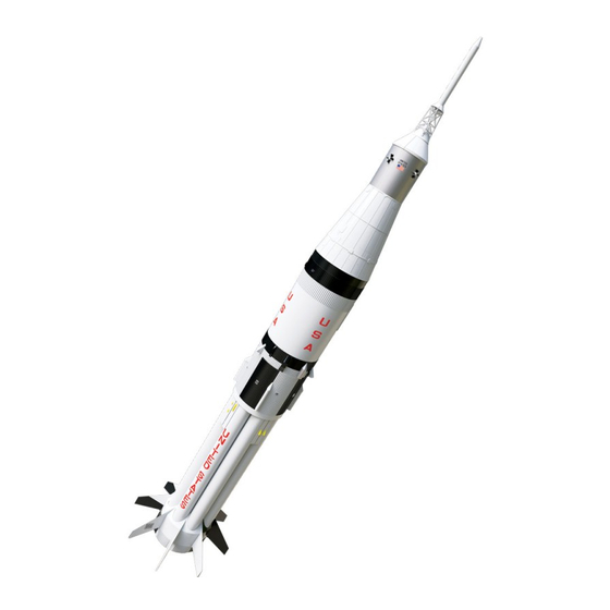
1967 Retro
Reproduction
1/70 Scale Model
Flies on a single
24mm motor or a
Cluster of four
18mm motors
Laser Cut Parts
Embossed
Wraps
Dual 18"
Parachute
Recovery
Made in the U.S.A by Semroc - Dayton, Ohio
Specifications
Body Diameter
Length
Fin Span
Net Weight
Saturn 1B
Kit No.
3.938" (10.0cm)
37.7" (95.8cm)
8.2" (20.8cm)
9.9 oz. (280.9g)
Skill Level 4
ROCKET KIT
KS-1
Engine
Approx. Altitude
C6-3 (four)
D12-3
D15-4
FLYING
MODEL
600'
220'
325'
Advertisement
Table of Contents

Related Manuals for SEMROC Saturn 1B


Summary of Contents for SEMROC Saturn 1B
- Page 1 18mm motors Laser Cut Parts Embossed Wraps Dual 18” Parachute Recovery FLYING MODEL ROCKET KIT Made in the U.S.A by Semroc - Dayton, Ohio Saturn 1B KS-1 Kit No. Specifications Engine Approx. Altitude Body Diameter 3.938” (10.0cm) C6-3 (four) 600’...
- Page 2 Almost everyone remembers growing up launching Estes rockets or knowing someone who did. Estes Industries has introduced millions of peo- ple of all ages to model rocketry for almost half a century. October 15,2006, January 20, 2018 Copyright © 2006 Semroc www.semroc.com...
-
Page 3: Before You Start
About the Saturn 1B The Estes Saturn 1B was released in 1967. The cul- mination of over a year of development driven by Chief Illustrator Gene Street, the Saturn 1B was a major work of model rocketry art. Not quite an actu-... -
Page 4: Parts Identification
ASSEMBLY ❑ 1. These instructions are presented in a logical order to help you put your Semroc Saturn 1B together quickly and efficiently. Check off each step as you complete it and enjoy putting this kit together. NOTE: The Semroc Saturn 1B is not for inexperienced modelers. -
Page 5: Engine Mount
Done properly, a four engine cluster of C engines in a Saturn 1B is impressive. A single 24mm engine like the D12-3 will not reach the altitudes of the cluster, but is generally much more relia- ble. - Page 6 ❑ 5. Using a drawer or door facing, draw a line on the TR-9115 ring. Remove the cluster bulkhead (1) from the ring set. As with all the fiber parts, sand the hold-in tabs slightly and use a toothpick to soak each edge with cy- anoacrylate glue to keep them from de-laminating.
-
Page 7: Main Assembly
MAIN ASSEMBLY ❑ 9. Apply a bead of glue inside one end of one of the stuffer tubes (ST-990). These tubes are 9” long and should not be confused with the BT-51N tank tubes! In- sert the tube coupler (HTC-9) into one end of a tube to about 1/2”. - Page 8 ❑ 13. This step can be skipped if you have the single 24mm engine mount. Locate four of the fuel tubes (BT- 51N.) Mark a rectangle on the end of each tube 3/8” wide by 2-7/8” long. Carefully cut out a slot from all four of the tubes.
- Page 9 ❑ 16. Mark the end of each stuffer tube 1/8” from the end. The four slotted tubes should be marked at the op- posite end from the slot. (If the tubes were not slotted for the 24mm option, use any four tubes.) Glue the first slot- ted tank tube to the two stars as shown, with the slot over one of the engine mount tubes and the 1/8”...
- Page 10 ❑ 20. Apply fillets around each joint between the tank tubes and the tank cover. ❑ 21. Remove the 8 spacer strips (A) from the balsa sheets. Sand slightly to remove tabs. These will be cov- ered so finishing is not necessary. The strips are not square so glue the laser-cut edge to the tank tubes for best fit.
- Page 11 ❑ 24. Insert the lower cap ring (4) over the end of the motor mount and flush against the tank tubes. If you have the 24mm single mount, align the engine hook in the center of one of the holes. Apply a fillet of glue around all the joints.
- Page 12 ❑ 27. Carefully cut out the fairing shroud and glue the ends together with the glossy side out. Slide the fairing over the tank tubes and against the fairing supports and the tail ring. Check it for fit and trim slightly if necessary. Pull it back and apply a small bead of glue on each fairing rib and around the tail ring.
- Page 13 ❑ 31. Pull the shock cord out of the top of the para- chute tube so it is out of the way. Apply a bead of glue inside the end closest to the knot. Slide the main tube assembly into the parachute tube until the bottom ring is recessed 1/16”.
- Page 14 ❑ 35. Apply a bead of glue around the top of the para- chute tube ring and upper body top. Slide the LEM shroud over the parachute tube and into place over the parachute tube ring. fit the base of the shroud to the up- per body tube and smooth any excess glue.
- Page 15 Second Major Decision! The built-up fins are one of the most difficult steps in the construction of the Saturn 1B. They require lots of pa- tience, but give the best result. We have provided 1/8” laser-cut balsa fins as an alternate solution. At a distance, they are hard to tell they are not the real thing.
- Page 16 Engine Hooks EH-28 Engine Hook EH-38 Tubing Couplers HTC-9 Wood Dowel WD-212 Centering Ring Set (3) CR-KS-1 Body Wrap Set (5) IKS-1W Shroud Sheet Set (3) IKS-1S Chute Pak CP-12-18RW Decal Set DKS-1 Saturn 1B Ruler I KS-1R Instruction Manual IKS-1...
-
Page 17: Exploded View
EXPLODED VIEW... - Page 18 ❑ 41. Test the tip rib (E) for fit and add it next. It may be necessary to sand the edge of the trailing edge spar. Test fit the long brace rib (F) next. The bottom may need to be beveled to fit. Apply a small amount of glue and set it into place over the dotted line.
-
Page 19: Final Details
FINAL DETAILS ❑ 45. All the remaining small laser-cut fiber parts will be attached in the following steps. They are small and look very much alike so keep the parts identification page handy. As each piece is removed, a very light sanding should be used to get rid of any tabs. - Page 20 ❑ 48. Detach the two telemetry antennae (12) from the fiber sheet. Align them as shown below and glue into place on Wrap #5. They should be centered over the two flat spots on either side of the main channel. ❑...
- Page 21 ❑ 52. Make three discharge tubes as shown below. Cut a piece off one of the small launch lugs supplied (LL-180) using the guide. Cut out the discharge tube shroud and fold it around the launch lug with the glossy side to the outside.
- Page 22 ❑ 55. Attach the two vector control jet housings on Wrap #4 on the last two flat areas with the top edge even with the top of the wrap. ❑ 56. Build the four retro-rocket housings from the small launch lug material (LL-180) and the cut-outs from the shroud sheets.
- Page 23 1/2” long piece of the large launch lug about 1/4” from a fin and on the bottom of Wrap #2. Cut a 1/2” piece and using a small scrap piece of balsa as a standoff, glue it on Wrap #3 and in line with the lower launch lug. Make sure it clears the camera target (11).
- Page 24 Fill ‘n Finish or sanding sealer. Wipe any dust from your model. ❑ 64. The Saturn 1B should be painted with a base coat of gloss white paint. A spray enamel paint works best for this. Support your model using a dowel in the...
- Page 25 body tube and 1/4” to the right of the antenna panel. Ap- ply the tape smoothly down the tube, centered between joints. Apply the other three pieces of tape, each on the tank to the right of an antenna panel. Apply a thin coat of white along each edge with a brush.
- Page 26 Paint the bottom cap ring gold. APOLLO CAPSULE ❑ 76. While the paint is drying, set the Saturn 1B aside and begin the assembly of the Apollo Capsule kit. It has its own parachute that also has to be assembled.
- Page 27 ❑ 81. Cut the #3 decals from the large sheet. They should be applied with the long sides parallel to the base of the ring tube and mounted to the right of fins at POS I, II, III, and IIII. The bottom edge is .34” above the joint be- tween Warps #1 and #2 and the left edge of the decal is .42”...
- Page 28 PAINT DETAILS AND DECAL LOCATIONS Color Scheme White Main Body Retro-Rocket Housings Discharge Tubes Antenna panels Black Roll patterns Fins, shroud, and tail cone as above Fuel tanks Silver Antennae Gold Heat shield (rear cap-ring)
- Page 29 Decals on the opposite side of the fin are meas- ured to the lower right corner of each decal.
- Page 30 Carefully check all parts of your rocket before each flight as a part of your pre-flight checklist. Launch the Saturn 1B from a 1/8” diameter by 36” long launch rod. A longer rod will result in better flight control and...
-
Page 31: Limitation Of Liability
Sem- roc products on these conditions. Your purchase and use of any Semroc products is construed as your agreement to and acceptance of these terms. If you do not agree to these terms and conditions, you must return the product, unused, for refund or credit. - Page 32 1. Materials. I will use only lightweight, non-metal parts for the nose, body, and fins of my rocket. 2. Motors. I will use only certified, commercially-made model rocket motors, and will not tamper with these motors or use them for any purposes except those recommended by the manufacturer.
Need help?
Do you have a question about the Saturn 1B and is the answer not in the manual?
Questions and answers