
Related Manuals for EXHOBBY Phoenix S


Summary of Contents for EXHOBBY Phoenix S
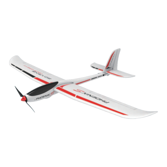
- Page 1 SPECIFICATION Motor Brushless 2212/1400KV Brushless 30A Servo 9-gram servo x 4pcs Battery 7.4V 1500mAh Li-Ion Propeller 10-inch folded...
-
Page 2: Safety Precautions
WARNING The following terms are used throughout the product literature to indicate various levels of potential harm when operating this product. CAUTION: Procedures, which if not be properly followed, is able to create a possibility of physical property damage AND or possibility of injury. Read the ENTIRE instruction manual to become familiar with the features of the product before operating. -
Page 3: Box Contents
- By handling, charging or using the included battery, you shall assume all risks associated with Li-Po/Li-Ion/Ni-Mh battery. - If at any time the battery begins to balloon or swell, discontinue use immediately. If charging or discharging, you should discontinue and disconnect. Continue to use, charge or discharge a battery that is ballooning or swelling can result in - Always store the battery at room temperature in a dry area for best results. - Page 4 Charging Instruction(RTF) Balance Charger Lithium Battery 1. Plug the included balance charger to the power adaptor cable, then plug the power adaptor into a compatible AC outlet(depends on different contries and area) , then connect the power output lead to the receptacle on the side of the balance charger The power adapter and balance charger are powered on whe n the green color LED indicator is glowing.
-
Page 5: Setup Instruction
Setup Instruction 1. Install the control horns to the tail part as shown above. Make sure the horn legs are secured through the plates. 2. Install the horizontal and vertical tails 3. Secure the tail part to fuselage with 4pcs with 2pc s PA2.6*8mm screws. -
Page 6: Center The Control Surfaces
6. Install the pushrod to connect the servo 7. Assemble the main wings with the bar arm and the surface control horn for each connected. Make sure you hear a click part of the main wings. sound to secure the main wings to the fuselage. - Page 7 After connecting the clevis to the control horns, observe the rudder to see if it is centered. If it is angled off to the right or left, you can adjust the length/position of the push rod/ clevis so that the surface is centered. Repeat the steps on elevator and aileron to ensure the surfaces are center too.
-
Page 8: Propeller Assembly
Propeller Assembly Propeller Base & Blades Shaft Adaptor Screws Assemble the propeller by the order as shown. WARNING: Do NOT power on the airplane while assembling the propeller, or serious damages may cause! Spinner Washer Center of Gravity The ideal C.G. position is 70±5mm behind the leading edge measured at where the wing meets the fuselage . -
Page 9: Flying Conditions
Find a Flight Field crowded neighborhood areas or in areas that are not free of people and obstructions. more forgiving surface that causes less damage in the unfortunate event of a c rash. Short grass i s better for takeoffs and landings as grass that is too takeoffs and landings on a smoother surface (such Fly in spacious ground w ithout obstacles and boskage. -
Page 10: Rog(Rise Off Ground) Take Off
With the antenna on the transmitter collapsed (not extended ) , begin walking away from the model operating the controls in a predictable pattern (for example: Up, then down elevator. Right, then left aileron. Right, then left rudder). While moving the control surfaces, also vary motor rpm. Have your assistant alert you if the controls fail to respond or if they move suddenly or erratically. -
Page 11: After Flight
Flying make the plane bank to your right. pilot!). the model into a bank. To stop the turn, apply a small amount of opposite aileron. straight without any control inputs. Often, your assistant can reach over and adjust the trims for you. do this, while still at altitude, cut the motor power.The model should establish a gentle, downward glide path.
Need help?
Do you have a question about the Phoenix S and is the answer not in the manual?
Questions and answers