Table of Contents
Advertisement
Advertisement
Table of Contents

Related Manuals for EXHOBBY Volantex RC 768-1 Mustang P-51D


Summary of Contents for EXHOBBY Volantex RC 768-1 Mustang P-51D
- Page 1 768-1 Mustang P-51D User Manual...
- Page 2 The following terms are used throughout the product literature to indicate various levels of potential harm when operating this product. CAUTION: Procedures, which if not be properly followed, is able to create a possibility of physical property damage AND or possibility of injury. Read the ENTIRE instruction manual to become familiar with the features of the product before operating.
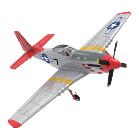
- Page 3 1. Main wing 2. Fuselage 3. Horizontal Tail 4. Landing Gear 5. Propeller 6. Spinner 7. Philips Screw Driver 8. Screws bag 9. Radio Transmitter(RTF) 10. Lithium Battery(RTF) 11. USB Charger(RTF) 1. Insert the elevator through the 2. Install the screw through the fuselage.
-
Page 4: Center The Control Surfaces
5. Install the landing gear to the 6. Install the propeller with spinner gap on the battery cover and fix to the motor shaft. it by screw . Center the control surfaces With the transmitter turned on and the LiPo flight battery connected to the ESC (and installed in the battery compartment) it’s now possible to connect the push rods to the rudder and elevator control surfaces and to ‘center’... - Page 5 After connecting the clevises to the control horns view the vertical tail and rudder from directly above. The rudder should be ‘in line’ with the vertical tail when it’s properly ‘centered’. However, if the rudder is angled off to the right or left you can adjust the length/position of the pushrod/clevis so the surface is centered ‘mechanically’...
- Page 6 The ideal C.G.position is 68±5mm behind the leading edge measured at where the wing meets the fuselage . The C.G. has a GREAT effect on the way of the model flight. If the C.G. is too far aft ( tail heavy ), the model will be too re- sponsive and difficult to control.
- Page 7 CAUTION: All instructions and warnings must be followed exactly. Mishandling of Li-Po/Li-Ion/Ni-Mh batteries can result in fire, personal injury, and/or property damage. - The battery charger included with your plane(if there be) is designed to safely balance and charge the specific Li-Po/Li-Ion/Ni-Mh battery. - By handling, charging or using the included battery, you shall assume all risks associated with Li-Po/Li-Ion/Ni-Mh battery.
- Page 8 Setup Your Receiver Indicator LED Aileron Rudder Elevator Antenna Install the receiver in your vehicle using double-sided tapes. The tapes will hold the receiver in place and help keep it from vibrations. Make sure the receiver is installed at a level plate so that the gyro works normally. CAUTION: Do NOT cut the antenna.
- Page 9 Gyro Switch(Flight Control) Instruction Expert (Manual Control) Medium (Regular Flight Control) Beginner (Strong Flight Control) Channels Reactions Checking Gyro Test Swing The Transmitter Reaction Reaction Plane Operaton Place your plane in a neutral position, follow below steps to check the channels reactions.
- Page 11 Flight Control System Calibration 1.Turn the throttle stick to min position. 2.Power on the transmitter and the receiver. 3.Do NOT unlock the throttle. 4.Keep the sticks as above picture for several seconds. 5.When you hear a “beep” sound, it means the flying control system is calibrated based on the horizontal level you are keeping it.
-
Page 12: Charging Instruction
Channels Reverse WARNING: Normally this function is not necessary to be operated. Only operate the below steps when you understand completely of the channel reverse function. WARNING: Do NOT reverse throttle otherwise serious damage would cause! 1.Turn the throttle stick to min position. 2.Power on the Transmitter and the receiver. -
Page 13: Flying Conditions
Find a Flight Field crowded neighborhood areas or in areas that are not free of people and obstructions. more forgiving surface that causes less damage in the unfortunate event of a c rash. Short grass i s better for takeoffs and landings as grass that is too takeoffs and landings on a smoother surface (such Fly in spacious ground w ithout obstacles and boskage. -
Page 14: Perform A Range Check
Perform a Range Check performing a range test is a good way to detect problems that could cause loss of control such as low batteries defective or damaged radio components or radio interference. This usually requires an assistant and should be First turn on the transmitter. -
Page 15: Hand-Launch
Hand-Launch advance t he t hrottle to full power. Y our assistant should run a few s teps w ith the p lane held high above h is head, and then give the model a swift, but controlled toss at a level, or slightly nose - up attitude.Initially, the elevator to establish the climb. -
Page 16: After Flight
After Flight Disconnect the battery and remove it from the airplane. Then, turn off the transmitter. Allow the battery to cool airplane to make sure nothing has become loose or damaged.
Need help?
Do you have a question about the Volantex RC 768-1 Mustang P-51D and is the answer not in the manual?
Questions and answers
No funcionan los alerones