
Summary of Contents for Wavetec Spectra
- Page 1 Wavetec Pvt. Ltd. Spectra Controller Installation Guide Rev 1.0 Haider Ali 9/4/2020...
-
Page 2: Document History
Document History Revision Date Comments Prepared By April 09, 2020 First Release Haider Ali... -
Page 3: Table Of Contents
Picture of Spectra controller unit......................6 Front View: ............................ 6 Back View: ............................. 6 Ports Description ........................... 7 Setting up Spectra ..........................9 Setting up Spectra in wired system ....................9 6.1.2 TCP/IP Mode (Recommended) ..................... 9 6.1.3 Serial Mode (over RS485)....................11 Providing LAN connectivity: ...................... -
Page 4: Introduction
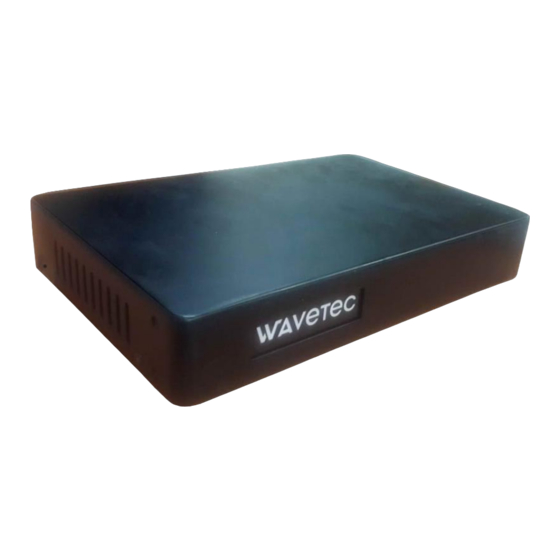
1. Introduction This guide defines the installation procedure of Spectra Controller. Spectra controller is the main component in EQ system and can be used to drive displays which is described in this document. The back side of the controller has all the ports and the front side has the company’s logo that glow when unit is powered ON. -
Page 5: Dimensions And Mounting
3. Dimensions and Mounting The Dimensions of the Spectra unit alone are 42 (H) x 260 (W) x 170 (D) mm Dimensions are in mm... -
Page 6: Picture Of Spectra Controller Unit
Rack Mount Brackets These two brackets can be screwed on sides of spectra unit in order to mount it on rack. 4. Picture of Spectra controller unit 4.1 Front View: 4.2 Back View:... -
Page 7: Ports Description
5. Ports Description Back panel of Spectra: Volume Knob- Rotate clockwise to increase volume To Active HUB “IN” Port (Only used in serial mode) RS485 (Cat5e/CAt6) Cat5e/Cat6 LAN cable 2 x 8Ω speaker Ethernet switch Power adapter To connect external 12V 3.34A... - Page 8 Two USB 2.0 ports can be used to connect peripherals like keyboard and mouse. One USB OTG port can be used for upgrade. LAN port For providing internet or LAN connectivity to the unit. LED indicators: Wavetec Logo with White Backlit LED that glows when unit is powered ON.
-
Page 9: Setting Up Spectra
6. Setting up Spectra 6.1 Setting up Spectra in wired system 6.1.2 TCP/IP Mode (Recommended) Wiring Diagram: Output- RS485 (Cat5e/CAt6) Power adapter 2 x 8Ω Ethernet Volume Knob- To connect 12V 3.43A speaker switch external Rotate amplifier clockwise to increase... - Page 10 Description: Connect the Spectra controller as shown in wiring diagram above. When using TCP Active Hub, Spectra can be configured to transfer data for displays (CDUs, SDUs and PDUs) and HTSUs over TCP/IP connection to TCP Active Hub.
-
Page 11: Serial Mode (Over Rs485)
1) Driving displays (CDUs, SDUs and PDUs): In order to drive displays connect one end of patch cord (Straight cable – RJ45 on both ends) to port marked “CDU” in Spectra and other end to Active Hub/TCP Active Hub port marked “IN”. -
Page 12: Providing Lan Connectivity
Note: It is recommended to use Cat5e or Cat6 LAN cable/Patch cord Length of wire between Spectra controller “CDU” port and “IN” port of Active Hub can go up to 50m. 6.2 Providing LAN connectivity: Connect a LAN cable/Patch cord from network switch to LAN port on Spectra controller in order to provide internet or LAN connectivity. -
Page 13: Debugging
7. Debugging: 8. Upgrading Spectra / Updating Patch For upgrading system For upgrading system... -
Page 14: External Amplifier - Connections
9. External Amplifier - Connections Audio Aux Cable 3.5mm 2 x 4Ω/8Ω Power adapter speaker... -
Page 15: Wiring Diagram With Whole System
10. Wiring Diagram with whole system... - Page 17 This device complies with part 15 of the FCC Rules. Operation is subject to the following two conditions: (1) This device may not cause harmful interference, and (2) this device must accept any interference received, including interference that may cause undesired operation. FCC warning: Any Changes or modifications not expressly approved by the party responsible for compliance could void the user's authority to operate the equipment.
Need help?
Do you have a question about the Spectra and is the answer not in the manual?
Questions and answers