
Related Manuals for Mountup MU0012-24K


Summary of Contents for Mountup MU0012-24K
- Page 1 MU0012-24K INSTALLATION INSTRUCTION Velcro cable ties X5 Bubble level X1 HDMI cable X1 Mounting template X1 Max:600x400mm/24x16" Max: 42"~70" 100LBS Min:200x100mm /8x4" 45.5KG (A0) If you have any questions, please contact us via help@jollyholding.com - 1 -...
- Page 2 Safety Caution combined. ● Do not apply this product to any purpose not indicated by MOUNTUP. ● Incorrect installation may result in product damage or body injury. MOUNTUP shall bear no responsibility for any damage or injury resulted from incorrect installation, incorrect assembly or misuse.
-
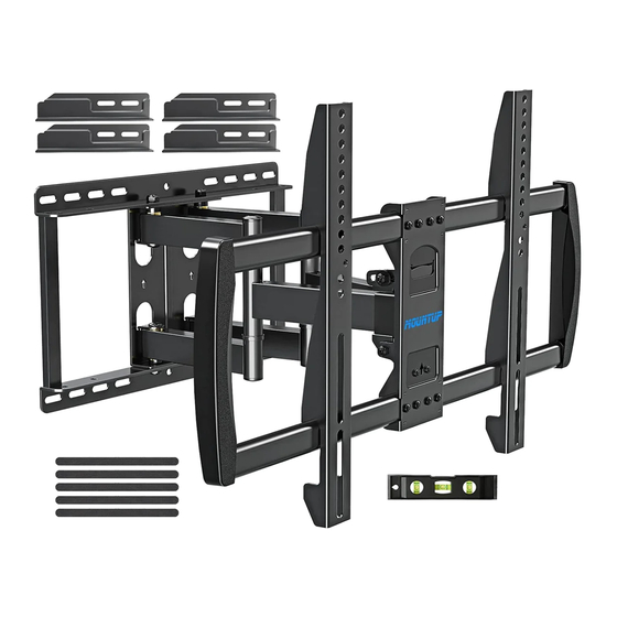
Page 3: Hardware Included
Hardware Included Arm and Wall Plate Arm Extensions Front Support End Cap Brackets Extension L Extension R Hardware Extention Kit (Wall /Product) Washers Open end wrench Bolts Nuts Lag Bolts Ø8mm M6 x 12 5/16 x 2½ in TV Screws / Washers Philips Screws Philips Screws Philips Screws... - Page 4 STEP 1-1 Select TV Screw Diameter Thread screws by hand into the threaded holes on the back of your TV to select which screw diameter fits your TV. STEP 1-2 Select TV Screw Length Too Short Too Long Correct Correct - 4 -...
-
Page 5: Step 1-3 Attach The Brackets
STEP 1-3 Attach the Brackets Position your brackets over your TV hole pattern - making sure the brackets are centered and level over the TV hole pattern. Secure the brackets using your screw/washer/spacer selection: (a) For Flat Back (b) For Round Back / Extra Space CAUTION: Ensure bracket is securely fastened before moving on to the next step. - Page 6 STEP 2A Wall Plate Installation (Wood Stud) 2A-1 Locate your studs. Verify and mark the center of the studs by finding the stud edges using an awl, a thin nail, or an edge-to-edge stud finder, then measure the space of the studs and record.
- Page 7 2A-3 Position the mounting template at your desired height and line M o u n t i n g t up the holes with your stud e m p l a t e mounting center line. Level the template and mark the pilot hole locations.
- Page 8 STEP 2B Wall Plate Installation (Concrete or Brick) 2B-1 Position the mounting template at your desired height , level the mounting template and mark the pilot hole locations. M o u n t i n g t e m p (no need to use the extensions l a t e for the concrete or brick...
- Page 9 STEP 3 STEP 3 Install Front Support and Extensions and End Cap together Install the extensions [03] to front support [02] with the pre-assembled screws. 2. Remove the pre-assembled screws x4 1. Loosen a little 3. Insert the arm extension 4.
- Page 10 Hang 02 onto 01 and using a screwdriver to secure with preassembled screws and washer STEP 4 Hang TV with Brackets onto the Arm Extensions Remove the preassembled screws [P3] and Press the safety locks save to use, then then fasten the removed raise the safety screws [P3].
- Page 11 Adjustments (Tilting) Loosen Tilting angle adjustment (+3° / -12°) Tighten Loosen tilting nuts, pull TV to your desired angle, then fasten tilting nuts with open end wrench (Leveling) Loosen TV leveling adjustment (-3°/+3°): ±3° Loosen 2 leveling bolts on the rear of TV plate with the open end wrench Tighten adjust to level, and retighten to secure.
-
Page 12: Product Dimensions
Product Dimensions: ” ” + /- ° ” ” ” ” ° - 12 -...
Need help?
Do you have a question about the MU0012-24K and is the answer not in the manual?
Questions and answers