
Related Manuals for Mountup MU0031


Summary of Contents for Mountup MU0031
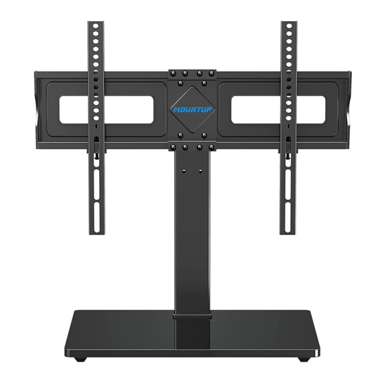
- Page 1 MU0031 Table Top TV Stand Installation Manual Min: 150x100mm / 6x4" 37~70" 88lbs Max: 600x400mm / 24x16" 40kg V1.0 If you have any questions , please contact our customer service.
- Page 2 MOUNTUP shall bear no responsibility for any damage or injury resulted from incorrect installation, incorrect assembly or misuse. ● Do not apply this product to any purpose not indicated by MOUNTUP. If this mount is NOT compatible, please contact our customer service to nd a compatible mount.
-
Page 3: Package Contents
PACKAGE CONTENTS ① (×1) ② (×1) ③ (×1) Base Support Pillar Support Pillar ④ (×2) ⑤ (×2) ⑥ (×1) ⑦ (×1) TV Bracket TV Plate Connecting Plate Angle Adjuster A (×3) B (×1) C (×4) D1 (×4) D2 (×4) E (×4) Bolt M6×30mm Washer M6 Nut... - Page 4 STEP 1: Support Pillar Installation Step 1-1: Connecting two Support Pillar (②&③). Insert 4pcs Screws (E) through the holes of Support Pillar (②&③), use the 4mm Allen Key (J1) to tighten them. ③ Checklist ② ② (x1) Support Pillar ③ (x1) Support Pillar E (x4) Bolt M6×10mm...
- Page 5 STEP 2: Apply Foot Pads to the Base Tear o plastic lm of Foot Pads (I), then attach Foot Pads (I) on the bottom of the Base (①) at the corners. ① Table Checklist I (x4) Foot Pad STEP 3: TV Plate Installation Step 3-1: Connecting TV Plate (⑤) and Angle Adjuster (⑦) by using Connecting Plate (⑥) and s (C).
- Page 6 STEP 3: (Continued) Step 3-2: Choose the appropriate position (three options) for your TV Plate, connecting TV Plate Unit to Support Pillar(②) by using Bolts(D1) and Washers(D2). Use the 4mm allen key(J1) to tighten them. TV Plate Unit ② Note: Arrow must be up! Checklist D1 (x4) Bolt M6×50mm...
- Page 7 STEP 4: Attach the TV Brackets 1-1 Select TV Screws Too Short Too Long Not Vertical Correct Correct 1-2 Need Spacer? Yes, choose the appropriate screws, washers, and spacers for your TV. Long Screw Washer Spacer Bracket Flat Back...
- Page 8 STEP 5: Attach TV with Brackets to TV Plate Choose the appropriate position (three options) for your TV. Hang TV with brackets onto the TV plate. Put the safety lock (G) in place and tighten the xing screw to the TV plate securely. Note: 45mm Three choices for...
-
Page 9: Step 6: Cable Management
STEP 6: Cable Management Attaching Wire Clips (H) into the holes of Support Pillar (②&③). Manage cables with the Wire Clips (H). ② ③ Checklist H (x2) Wire Clip... - Page 10 Adjustments Swivel Adjustment Refer to below illustrations to adjust swivel angle. -20° +20° Note: When the TV Stand is placed against the wall, the actual swivel angle is determined by the screen size. Wall Tilt Adjustment (If necessary) 1. Loosen 4 tilting bolts by MAXIMUM 1 turn with (J2).
-
Page 11: Product Dimensions
Product Dimensions 633mm/24.92" MAX:600mm/24" MIN:150mm/6" MAX: +5° 400mm/16" MIN: MAX: 100mm/4" 788mm /31.02" 110mm MIN: /4.33" 588mm /23.15" 0° 571mm /22.48" 23mm /0.91" 40mm 70mm /1.57" /2.76" 280mm /11.02" 130mm /5.12" +20°/-20° 420mm/16.54"... - Page 12 CAUTION AND MAINTENANCE: • Never allow children to climb, stand, hang, or play on any part of TV or stand. • This product is intended for indoor use only. Using this product outdoors could lead to product failure and personal injury. •...
Need help?
Do you have a question about the MU0031 and is the answer not in the manual?
Questions and answers