TAKAYA APT-9411 Series Service Manual
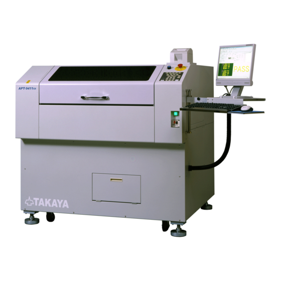
Fixtureless tester
Hide thumbs
Also See for APT-9411 Series:
- Operator's manual (63 pages) ,
- Operator's manual (31 pages) ,
- Operator's manual (15 pages)

Subscribe to Our Youtube Channel
Related Manuals for TAKAYA APT-9411 Series


Summary of Contents for TAKAYA APT-9411 Series
- Page 1 T-941 1 1 S 1 Se e r r i i e e s s Se Ser r v v i i c c e e M M a a n n u u a a l l TAKAYA CORP. TAKAYA CORP.
- Page 4 Vo ory in Vol l .2 .2 This Service Manual accommodates the APT-9411 Series which serial number is V5F4**23 or later. This Service Manual accommodates the APT-9411 Series which serial number is V5F4**23 or later.
- Page 6 1) The company name and the product name described in the service manual are the trademark of each company. 2) Copyright 2004 Takaya Corporation. All rights reserved. No portion of the contents of this publication may be reproduced or transmitted in any form or by any means without the express written permission of TAKAYA Corporation.
- Page 7 Precausions The TAKAYA Fixtureless Tester is composed of precise mechanisms and the electric circuits. Please keep this service manual handy to get a better understanding of the product before you start the installation and/or maintenance work. Operating and Safety Symbols...
-
Page 8: Table Of Contents
Contents Preface ..............1 Precautions ..............2 Contents ..............3 1 Specification Dimensions and weight ..............1-2 Names and function of parts Exterior ..................1-3 XY arm................... 1-5 Z arm ..................... 1-7 PCB holder unit ................1-8 Inside chassis ................ - Page 9 Contents Contents 3 Maintenance 3 Maintenance Grease Grease care care..................3-2 ..................3-2 Printer Printer Printer Printer ......................................3-5 Replacing Replacing printer printer paper paper ........................... . 3-5 Replacing Replacing probe probe pin Probe 1/4..................3-8 Probe 1/4..................3-8 Probe 2/3..................
- Page 10 Contents Contents 5 Constituent parts 5 Constituent parts Page Page composition composition ................5-3 ................5-3 Exterior Exterior Exterior Exterior cover cover (F (F, , R) R) .............................. 5-5 Exterior Exterior cover cover (B, (B, L) L) ............... 5-7 ...............
- Page 11 S S pec peci i fi fic c a a ti tion In this chapter you will find the size dimensions, the name of key components and specifications. In this chapter you will find the size dimensions, the name of key components and specifications. Dimensions Dimensions and and weight...
-
Page 12: Dimensions And Weight
1-1 Dimens ions and weig ht Dimensions and weight of the product is as per the drawing below. Please take them into account especially when this is your first time installation or movement. 2060mm 81" 1370mm 690mm 54" 27" Monitor base Max 8kgs 1270mm 50"... -
Page 13: Names And Function Of Parts Exterior
1-2 Names and function of parts Exterior Names and function of the exterior parts are explained below. ! Emergency stop SW # Operation panel " Reset SW ( Monitor * Clamp lever & Earth terminal - Cover SW(Left side) + Mouse $ Tester terminal , Keyboard % PC access window... - Page 14 1-2 Names and function of parts Name Function Reference Power SW The product turns on and off. The lamp lights in green color only when the Power ON lamp Power SW turns on. The product comes to a standstill on the spot and Emergency stop SW never actuate until the SW is released.
-
Page 15: Xy Arm
1-2 Names and function of parts XY arm Names and function of the parts used at XY arms are expla ined below. ' Y2 motor . X2-3 stopper ' Y3 motor ' Y1 motor ' Y4 motor + X1 stopper , X4 stopper ... - Page 16 1-2 Names and function of parts Name Function Reference X motor Y motor Driving motors Probe motor " X sensor Page 3-15 Home sensors for each axis Position of sensors Y sensor X cover plate Cover plates to turn on and off the Home sensors Y cover plate &...
-
Page 17: Z Arm
1-2 Names and function of parts Z arm Names and function of the parts used at Z arms are explained below. ) Motor & LED lamp # Sensor (Z4 top side) - Cover plate & LED lamp (Z1) & LED lamp (Z4 front side) "... -
Page 18: Pcb Holder Unit
1-2 Names and function of parts PCB holder unit Names and function of the PCB holder unit are explained below. & Handle ! Rear PCB holder + Support pin . Bottom probe ( Cable holder ' Front PCB holder , Machine ref. point(F) # Knob for adjusting PCB width "... -
Page 19: Inside Chassis
1-2 Names and function of parts Inside chassis Names and function of the parts inside the chassis are explained belo w. ) Personal computer ' CCU camera # Power panel ! Terminal 14 " Terminal 3 - Power panel (for measurement unit) &... - Page 20 1-2 Names and function of parts Name Function Reference Page 1-12 Personal computer Personal computer & Monitor Page 2-11 CCU camera Controller for camera CCD camera Terminal 14 AC100V OUT Terminal Page 2-12 Connection " Terminal 3 AC200,220,240V OUT Terminal Power panel Power panel Page 4-1...
-
Page 21: Serial Number
1-3 S erial number This section explains the serial num ber that identifies each tester individually. Every tester has an identification plate with a serial number on the back. This serial number will be necessary for efficient maintenance service. Be sure to tell us the serial number whenever the maintenance parts or some optional items would be required. -
Page 22: Personal Computer & Monitor
1-4 Pers onal computer & Monitor Under-mentioned is minimum requirements to the personal computer and the monitor usable in the tester. System Requirements Computer PC/AT compatible PC Pentium 4 2GHz or higher Memory 512MB or more CD-ROM 1 drive 4GB or more (Free space needs approx. -
Page 23: Accessories
1-5 A ccess ories Followings are standard accessories included in the tester. Name Type Remarks XX-00222 Probe pin SA941-46616P0 Probe socket TAKAYA LS-458-01 Probe 1/4 Probe wire TAKAYA LS-457-01 Probe 2/3 PTP-2N1LLM-3R Probe pin Bottom probe Cable holder TLA-201... - Page 24 Installation In this chapter you will find the way to install and set up the tester, its peripheral equipments and the CCD camera so on. Installation Movement..................2-2 Adjustable height margin ............... 2-3 Leveling pad .................. 2-3 Leveling the tester ................. 2-4 Fixing brackets ................
-
Page 25: Movement
2-1 Ins tallation Movement The case that the forks are inserted under the chassis in order to lift and move it to other location is described below. As for the footprint necessary for the t ester, please refer to 1-1 Dimensions and weight . DANGER Never fail to use the fork lift that supports the weight of the tester and deal with the frame size. -
Page 26: Adjustable Height Margin
2-1 Ins tallation Adjustable height margin The height margin adjustable by " Leveling pads equipped under the chassis is described below. Adjustable margin 900mm+70, -20 35"+2.8, -0.8 Standard inspection height 900mm 35" Leveling pad Leveling pad The way to adjust the leveling pads is explained below. CAUTION In order to level the tester, adjust the four leveling pads equipped under the chassis little by little carefully. -
Page 27: Leveling The Tester
2-1 Ins tallation Leveling the tester Try to level the tester with a water level as described belo w. (NOTE) As a water level is not standard accessory, be sure to bring it with you when the tester is introduced to the user. Operating steps: (NOTE) Pay attentions not to lift another level pad while working the operation below. -
Page 28: Fixing Brackets
2-1 Ins tallation Fixing brackets Fixing brackets installed at the deliver y as described below. CAUTION Be sure that any removed materials, such as fixing brackets, vinyl bands and screws never remains inside the tester. Fixing bracket-X There is a fixing bracket (red color) between the 2Y arm and the 3Y arm as illustrated below. Please open the rear exterior cover in order to take it out of the tester. -
Page 29: Monitor Base
2-1 Ins tallation Monitor base Install Monitor base as described below. Install the Monitor base to the Swing arm. Monitor base Swing arm Screw Install the monitor on the Monitor base and fix it with Monitor brackets. Monitor Monitor bracket Washer Wing nut Monitor bracket... - Page 30 2-1 Ins tallation Run all cables through a mounting hole on the Monitor base. Monitor power cable Monitor cable Keyboard cable Mouse cable Mounting hole Break down into Wiring hose, Joint and Nut as illustrated below. Joint Wiring hose (Inside) Wiring hose Wiring hose (Outside) Disassembly...
- Page 31 2-1 Ins tallation Run the cables through the Wiring hose (Inside) and cover it with the Wiring hose (Outside). Wiring hose (Inside) Wiring hose (Inside) Wiring hose (Outside) Cable Install the Nuts at both ends of the Wiring hose. Wiring hose Joint Joint Put the Nut on the cables.
- Page 32 2-1 Ins tallation Use the Nut to fix the Wiring hose on the Monitor base. Monitor base Joint Wiring hose Insert the cables through a Mounting hole on the Side cover, and put the Nut on the cables inside the Side cover.
-
Page 33: Peripheral Equipments Personal Computer
2-2 Peripheral equipments Personal computer Installation of a personal com puter is explained below. WARNING Make sure that the tester is powered off and unplugged before starting your operation. Otherwise it could possibly causes bodily injury or mechanical trouble. Remove Front cover to draw PC stage out of the tester and place a personal computer there. (Refer to " 1-4 Personal computer &... -
Page 34: Printer
2-2 Peripheral equipments CCU (Camera control unit) Install a CCU as described below. (SW panel is upside) PC stage Screw CCU holder SHUTTER GAIN CONTROL POWER SPEED HIGH/OFF AUTO GAIN MANUAL LOW/F.L. CSU4000B HIGH/OFF MANUAL CCU setting IMPORTANT Whenever the camera (CCD, CCU and/or lens) would be installed or replaced locally by yourselves, be sure to fine adjust the camera gain. -
Page 35: Wiring Connection
Vision card (TOS/TTG) Monitor Motion control PCB (JAPMC-MC2110) I/O PCB (ZPCIOO1T@L00) Relay cable LS-470-01 Keyboard Keyboard relay cable I/F PCB TAKAYA TVX-30P VME relay cable Motor driver (X4) Mouse relay cable Mouse Terminal (TM3) Power cable VME PCB TAKAYA TVX-30V... - Page 36 Monitor cable Power cable M 5 cable Vision card (TOS/TTG) Monitor Motion control PCB (JAPMC-MC2110) Keyboard Keyboard relay cable I/O PCB TAKAYA TVX-30Z VME relay cable Motor driver (X4) Mouse relay cable Mouse Terminal (TM3) Power cable VME PCB...
- Page 37 2. Be sure to connect the I/O PCB to the I/F PCB with an interface cable. 3. It may differ slightly from the drawing below depending on the option items to be installed. Original Configuration I/O PCB (ZPCIOO1T@L00) Driver PCB (TAKAYA TVX-30P) Interface cable Motion control PCB (JAPMC-MC2110) TAKAYA LS-470-01...
- Page 38 2-2 Peripheral equipments Terminal (TM 3/14) is explained below. 1-2 Names and function of parts (NOTE) Refer to " " for the terminal TM 3/14. TM14 100V 200V 6.6mm max 220V 240V 3.2mm min AC FG AC Size 2 - 15...
- Page 39 2-2 Peripheral equipments The cables from the m onitor, the keyboard and the mouse and po wer cables are described below. IMPORTANT It may differ slightly from the drawing below depending on the PC and/or the option items to be installed. Mouse Cable TM14 (100V) Keyboard Cable...
- Page 40 It may differ slightly from the drawing below depending on the PC and/or the option items to be installed. Monitor cable Video cable Printer cable Vision card " VME relay cable Mouse relay cable (I/F PCB TAKAYA TVX-30P) Keyboard relay cable cable (Motion control PCB) (JAPMC-MC2110) PC Power cable Rear PC Original Configuration...
- Page 41 2-2 Peripheral equipments New Configuration I/O PCB (TAKAYA TVX-30Z) Motion control PCB (JAPMC-MC2110) Vision card (TOS Video cable (TOS) VME relay cable M 5 cable PC Slots 2 - 18...
-
Page 42: Connecting Power Supply
2-3 Connection power s upply Input voltage The position of a transformer connecting to the primary input voltage is explained below. DANGER Be sure to power off the tester and unplug before starting your operation. Otherwise it could possibly cause bodily injury or mechanical trouble. WARNING The tester is always preset to accept available power source at the destination. -
Page 43: Earth/Power Supply
2-3 Connection power s upply Earth/Power supply The power cable and the earth cable for the primary input voltage is explained below. The power cable has different length and nose shape depending on the user specifications. It is always necessary to earth the Earth terminal on the rear tester using a thick wire (0.75mm or more), except the case that the tester is properly grounded through the power cable in which the earth lead is included as standard. -
Page 44: Camera Installation
2-4 Camera ins tallation Camera installation This section explains how to install a CCD on the APT-9411 which was pre-installed with the lens. Followings items are necessary in the working process written in this document. <Tools> Name Type Hexagon wrench Full set Rule L=150mm... - Page 45 2-4 Camera ins tallation Please go through the following steps to install the CCD. WARNING The probes are keen-edged! You may get serious injury caused by carelessness. Operating step Power on the tester to boot up the APT system. Open " PCU Parameter menu (Ctrl + P key). Choose " Adjust tab and click " Adjust button under Adjust Camera.
- Page 46 2-4 Camera ins tallation Remove the Camera bracket-2 at the right hand by unscrewing Allen screw. (Refer to Fig.3) CAUTION Both the lens and its camera bracket were already fine-adjusted at delivery. So never attempt to loose the Allen screw illustrated in Fig.3. Otherwise it may cause a serious trouble. Allen screw Camera bracket-2 Never loose this Allen screw!
- Page 47 2-4 Camera ins tallation Connect the Camera cable to the CCD. (Refer to Fig.6) Camera cable Fig.-6 15. Power on the CCU unit. 16. Rotate the CCD carefully by hand in order to set the camera target in parallel with the Marker on the Camera Adjustment Jig (Slider).
- Page 48 2-4 Camera ins tallation 17. Make sure the camera focus agrees with the Maker level. The working process is described below. Move the Camera Adjustment Jig (Slider) to the location where " Focus stage is properly displayed on the monitor. (Refer to Fig.9) Loose the Knob-2 and move the Focus stage up/down.
- Page 49 2-4 Camera ins tallation Camera focus adjustment Move the Camera Adjustment Jig (Slider) to the location where " Focus stage is properly displayed on the monitor. (Refer to Fig.1) (NOTE) Marker level of the Camera Adjustment Jig (Slider) is the same height as the testing level. Camera Adjustment Marker level Jig (Slider)
- Page 50 2-4 Camera ins tallation Make sure the camera focus agrees with the Maker level. The process to check is described below. Loose the Knob-2 and move the Focus stage up/down. Fix the Focus stage with the Knob-2 at the position where the camera focus agreed with the Focus marker. (Refer to Fig.6) When the Focus stage is the same height as the Marker level, the camera focus should agrees with the Maker level so that all what you need to do is finished.
-
Page 51: Ccd Gain Adjustment
CC D G ain Adjus tment Standard operating procedure This section describes a certain procedures for adjusting the Gain at t he CCD CS4300B (CCIR;CS4300BC) with accuracy. Followings are all items necessary for your operation described in this document. <Tools> Name Type Q # ty... - Page 52 CC D G ain Adjus tment 31. Choose [1 7 *-Presence check], and click [OK] $ [TEST START]SW. After the camera moved over the Gain adjustment plate , press 8 key on the keyboard. (Refer to Fig.-3) Fig.-3 32. Now you see the histogram (for Camera Gain) on the Optical data review menu. Please adjust the histogram value (M:xx) to be within "...
-
Page 53: Safecover_Opening Position
2-5 S afecover_opening pos ition Since the middle of the production, the Safety cover has been provided with a height adjustable mechanism. You can choose two opening position of the Safety cover by relocating Gas spring joints that are installed at both sides of the Safety cover. - Page 54 Mai ntenance In this chapter you will find the information associated with necessary maintenance and replacement of consumable parts so on. Grease lubrication ................3-2 Printer Printer ..................... 3-5 Replacing printer paper ..............3-5 Replacing probe pin Probe 1/4..................3-8 Probe 2/3..................
-
Page 55: Grease Lubrication
3-1 Grease lubrication The tester mechanism is composed of high quality ball-screws and slide rails, and they are lubricated with grease that is made from Li-Soap Grease Lubricant and is water-proof and heat resistant at the delivery. It is unnecessary to lubricate these mechanical parts with grease within one year after delivered. However, after the tester was used for more than a year, you are recommended to check if grease film still coats them periodically (even a half year at least). - Page 56 3-1 Grease lubrication We will give a simple explanation as to how the mechanical parts on the Y-axes should be lubricated with grease. Parts Position Method/Type Rail Direct application with cloth or the brush. LM guide Li-Soap grease lubricant Screw (Direct to Screw) (Direct to rail) LM guide...
- Page 57 3-1 Grease lubrication We will give a simple explanation as to how the mechanical parts on the PCB holder unit should be lubricated with grease. Parts Position Method/Type Direct application with cloth or the brush. LM guide Rail Li-Soap grease lubricant LM guide (Direct to rail) LM guide...
-
Page 58: Printer
3-2 Printer Printer The standard printer (TSP-600) is explained below. Paper outlet POWER Lamp Top cover ERROR Lamp FEED SW POWER SW TSP600 POWER ERROR FEED Replacing printer paper You can change a roll of printer paper as described below. WARNING Opening the top cover or touching "... - Page 59 3-2 Printer Put a roll of printer paper into the printer as shown below. Printer paper Direction of printer paper Draw a tip of the printer paper out of the printer. Printer paper Draw out 3 - 6...
- Page 60 3-2 Printer Close the top cover by pushing both ends down. CAUTION Be sure that the top cover was fully closed and either side of the top cover is not open. Pull the chip of the roll paper and cut it out. Printer paper ...
-
Page 61: Replacing Probe Pin
R eplacing probe pin Probe 1/4 You can replace Probe 1/4 in the manner described below. WARNING Particular care should be paid to the keen-edged head of the probes to be replaced. Otherwise it may be an injury to your body. Select [Tool] à... -
Page 62: Probe 2/3
R eplacing probe pin Probe 2/3 You can replace Probe 2/3 in the manner described below. WARNING Particular care should be paid to the keen-edged head of the probes to be replaced. Otherwise it may be an injury to your body. 1. -
Page 63: Bottom Probe
R eplacing probe pin Bottom probe You can replace Bottom probes in the manner described below. WARNING Particular care should be paid to the keen-edged head of the probes to be replaced. Otherwise it may be an injury to your body. Pull the probe out of the socket, using needle nose pliers, so on. -
Page 64: Replacing Probe Wire
Remove the probe holder and pull out the probe wire straight. Joint a new probe wire to the probe and install the probe holder. (NOTE) Probe wire for Probe 1/4 is TAKAYA LS-458-01 L=280mm. Install the probe wire up to the PCB in the direction which a figure below directs. -
Page 65: Probe 2/3
Remove the probe holder and pull out the probe wire straight. Joint a new probe wire to the probe and install the probe holder. (NOTE) Probe wire for Probe 2/3 is TAKAYA LS-457-01 L=310mm. Install the probe wire up to the PCB in the direction which a figure below directs. -
Page 66: Replacing Sensor Probe
3-5 R eplacing s ens or probe Replacing sensor probe You can replace the sensor probes in the manner described below. WARNING Particular care should be paid to the keen-edged head of the probe. Otherwise it may be an injury to your body. - Page 67 3-5 R eplacing s ens or probe Fix the Sensor probe cable with the Cable holder ASSY. : TEST STOP ; SW. Close the Safe cover, then select [Close] and press [RESET] SW à Fix the Sensor probe cable here! Cable holder ASSY Sensor probe 3 - 14...
-
Page 68: Replacement Of Sensor Probe Base Cs8000-S21
3-5 R eplacement of S ens or probe bas e CS 8000-S 21 The information on how to replace Sensor probe base CS8000-S21 is described below. How to remove 1. Pull out the CS8000-S21 straight. (NOTE) Never try to pull it in an oblique direction so hard the sensor probe is bent. -
Page 69: Photoelectric Sensors
3-6 Photoelectric s ens ors Position of photoelectric sensors The tester incorporates lot of photoelectric sensors to monitor the actuators. Please refer to this section in case that you need to replace the photoelectric sensors and/or realign their position. WARNING All the photoelectric sensors are equipped with the tester under ultra-sophisticated adjustment at the manufacturer. -
Page 70: Motor Drivers
3-7 Motor drivers Location and model The motor drivers corresponding to each moving arms are installed as shown below. Location of motor driver (Viewed from the back) The model name of these motor drivers are shown blow. SGDS-A5A12AY35 SGDS-A5A12AY35 SGDS-01A12AY35 SGDS-01A12AY35 SGDS-01A12AY35 Model name of motor driver... -
Page 71: Replacement
3-7 Motor drivers Replacement The replacement of the motor driver is briefly described below. WARNING Make sure that the tester is powered off and unplugged before starting your operation. Otherwise it could possibly cause bodily injury or mechanical trouble. When a motor driver has to be replaced, be sure to verify SW 1 and SW2 and change the switch positions according to instruction in following page. - Page 72 3-7 Motor drivers SW Setting The switches of the motor driver are described below. WARNING Make sure that the tester is powered off and unplugged before starting your operation. Otherwise it could possibly cause bodily injury or mechanical trouble. SW1 and SW2 are on the motor driver as shown below. Use a precision standard screwdriver to turn on/off the SW.
- Page 73 E lectric diag rams In this chapter you will find the electric circuit diagrams and the physical location of the electric parts. Electric parts layout Major electric parts ................. 4-2 Switching power supplies ............... 4- 3 Motor drivers................... 4-3 PCBs ....................4-4 Circuit diagram System block connection diagram..........
-
Page 74: Electric Parts Layout
E lectric part layout Major electric parts Physical layout of switches, rela ys, terminals, and power supplies is introduced below. RESET E SW1 C SW1 (XCS-PA591) C SW2 (XCS-PA591) C.B1 (GV2-M14) C.B4 (GB2-CB06 1A) TM14 C.B3 (GB2-CB09 4A) N.F2 (MZ2-1206-33) C.B2 Transformer (NES2000CEN) -
Page 75: Switching Power Supplies
E lectric part layout Switching power supplies Physical layout of switching power supplies is introduced below. P.S5 JWS100-24/A P.S8 RWS30A-12/A P.S7 JWS50-24/A P.S6 RWS30A-5/A P.S4 RWS15A-48/A P.S3 RWS15A-15/A P.S2 RWS30A-15/A P.S1 JWS50-5/A Motor drivers Physical layout of motor drivers is introduced below. Motor drivers SGDS-A5A12AY35 SGDS-A5A12AY35... -
Page 76: Pcbs
E lectric part layout PCBs Physical layout of PCBs is introduced below. Probe-2 Probe-3 TAKAYA TVX-32A L1 TAKAYA TVX-32A L1 Probe-1 Probe-4 TAKAYA TVX-32A L2 TAKAYA TVX-32A L2 Probe-5/6 TAKAYA TVX-32A L1 TAKAYA TVX-36S L2 TAKAYA TVX-32A L2 TAKAYA TVX-37... -
Page 77: Circuit Diagram
4-2 Circuit diagram System block connection diagram Original Configuration Sensor 1 X H O M E L S Sensor 1 Y H O M E L S I/O P.C.B . 2 X H O M E L S CN10 I/O P.C.B . 1 Z H O M E L S 3 X H O M E L S 2 Y H O M E L S...
Need help?
Do you have a question about the APT-9411 Series and is the answer not in the manual?
Questions and answers
Is it possible to remove the granite from these machines for the purpose of recycling?