Table of Contents
Advertisement
Quick Links
Advertisement
Table of Contents

Related Manuals for NODEXON NX-6510S-20X4S2Q


Summary of Contents for NODEXON NX-6510S-20X4S2Q
- Page 1 NX-6510S-20X4S2Q Core/Aggregation Switch Product Guide...
- Page 2 This document is provided “as is”. The contents of this document are subject to change without any notice. Please obtain the latest information through the Nodexon Networks website. Nodexon Networks endeavors to ensure content accuracy and will not shoulder any responsibility for losses and damages caused due to content omissions, inaccuracies or errors.
- Page 3 It is intended for the users who have some experience in installing and maintaining network hardware. At the same time, it is assumed that the users are already familiar with the related terms and concepts. Obtaining Technical Assistance Nodexon Networks Website: https://www.nodexonnetworks.com/ Technical Support Website: https://nodexonnetworks.com/support...
-
Page 4: Product Overview
Quality of Service (QoS) policies, assigning different service flow with different bandwidth and ensuring no delay for key service flow. NX-6510S-20X4S2Q provides 20 10G SFP+ ports, four 25G SFP28 ports and two 40G QSFP+ ports. - Page 5 Rated input current: <3 A@90~264 VAC@full load Power < 85 W Consumption Refer to Appendix B Optical Module The supported modules may update at any time. Please contact Nodexon Networks for details. Temperature Support temperature warning and overheat protection. Warning GB9254-2008 CLASS A GB4943-2011 Altitude...
- Page 6 440 mm x 330 mm x 43.6 mm (17.32 in. x 12.99 in. x 1.72 in.), 1RU (W x D x H) The NX-6510S-20X4S2Q switch is a class A product. In a domestic environment, this product may cause radio interference in which case the user may be required to take adequate measures.
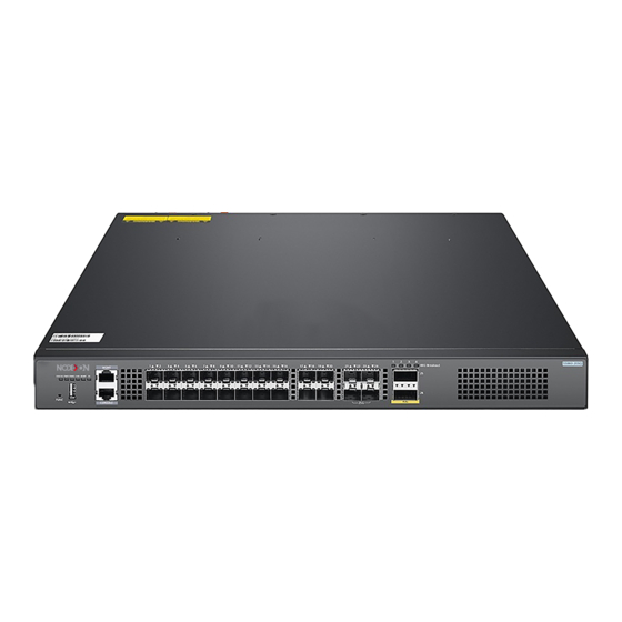
- Page 7 Nodexon NX-6510S-20X4S2Q Series Switch Product Guide Front Panel Figure 1-2 Front Panel of NX-6510S-20X4S2Q Note: 1. System indicator 10. SFP28 port indicator 2. PWR1 indicator 11. SFP28 port 3. PWR2 indicator 12. QSFP+ port indicator 4. Fan indicator 13. QSFP+ port 5.
- Page 8 4x10G mode. Button The NX-6510S-20X4S2Q switch provides a FUNC button for resetting the switch. Press the FUNC button and the system will start collecting information. After collection finishes, the switch will be reset automatically. Long press and short press both work.
- Page 9 Nodexon NX-6510S-20X4S2Q Series Switch Product Guide Identificatio Indicator n on the Status Meaning panel The system is powered off. 4) A system fault occurs. Solid red System indicator 5) The temperature reaches the upper limit. Status (Front panel/rear panel) Blinking green Initialization is in progress.
- Page 10 Nodexon NX-6510S-20X4S2Q Series Switch Product Guide The NX-6510S-20X4S2Q switch draws air from bottom to top using the rear panel fan to ensure that the device works properly in the specified environment. Make sure to maintain a minimum distance of 100 mm around the device for ventilation.
-
Page 11: Preparation Before Installation
Nodexon NX-6510S-20X4S2Q Series Switch Product Guide 2 Preparation before Installation 2.1 Safety Precautions To avoid body injury and device damage, please carefully read the safety precautions before you install the NX-6510S-20X4S2Q series switch. The following safety precautions do not cover all possible dangers. - Page 12 Direct or indirect touch through a wet object on high-voltage and mains supply can bring a fatal danger. The NX-6510S-20X4S2Q series switch has more than one input power supply. Please unplug all power cables after powering off the switch.
-
Page 13: Installation Site Requirements
Install the switch in an open cabinet as much as possible. If you install the switch inside a closed cabinet, be sure that the cabinet has a good ventilation and heat dissipation system. Be sure that the cabinet is firm enough to bear the weight of the NX-6510S-20X4S2Q series switch and its installation accessories. ... -
Page 14: Cleanness Requirements
2.2.5 System Grounding Requirements A good grounding system is the basis for the stable and reliable operation of the NX-6510S-20X4S2Q series switch. It is the key to prevent lightning stroke and resist interference. Please carefully check the grounding conditions on the installation site according to the grounding requirements, and perform grounding properly as needed. -
Page 15: Emi Consideration
Nodexon NX-6510S-20X4S2Q Series Switch Product Guide The device using AC power supply must be grounded by using the yellow/green safety grounding cable. Otherwise, when the insulating resistance decreases between the power supply and the enclosure in the device, electric shock may occur. -
Page 16: Precaution For Fiber Connection
Air-laid paper, fiber end microscope Meter Multimeter, errormeter, optic-power meter NX-6510S-20X4S2Q series switch is not shipped with a tool kit. You need to prepare a tool kit by yourself. 2.5 Package Contents Package Contents Chassis, Yellow/green grounding cables; Quick installation guide; Packing list, Pouched... -
Page 17: Product Installation
Bind cables or fibers Installation check 3.2 Installation Verification The NX-6510S-20X4S2Q series switch is a complicated device. Carefully plan and arrange the installation location, networking mode, power supply, and wiring before installation. The installation location provides sufficient space for heat dissipation. -
Page 18: Cabinet Installation
Precautions Before mounting the NX-6510S-20X4S2Q series switch into the cabinet, first verify that the front and back brackets of the cabinet are at the right locations. If the bracket is too far forward, the front panel of the device may be too close to... - Page 19 During the process of installation, keep the front panel of the switch forward. It is recommended use tray to install the NX-6510S-20X4S2Q series switch and fix the tray on the bracket, or use the rear bracket provided with the switch.
- Page 20 Nodexon NX-6510S-20X4S2Q Series Switch Product Guide The mounting brackets are located at the four of the six screw holes at both sides on the rear panel of the host. Distinguish the left and the right rear brackets according to the marked directions.
-
Page 21: Installing And Removing A Fan Module
Nodexon NX-6510S-20X4S2Q Series Switch Product Guide 3.5 Installing and Removing a Fan Module Wear anti-static gloves before the following operations. Installing an Fan Module Take out a new fan module from the fan module box. Hold the handle at the end of the fan module. Insert the fan module to the chassis slowly along the guide rail until it is fully seated, and make sure that it is in good contact with the slot. - Page 22 Nodexon NX-6510S-20X4S2Q Series Switch Product Guide Install the blank panel and put the removed fan module into its package Figure 3-5 Removing an M1SFAN I-F Fan Module Withdraw the fan module uprightly and slowly. Install a blank panel on the location where a fan module is removed to ensure normal ventilation and dissipation and avoid dust in the chassis.
- Page 23 Nodexon NX-6510S-20X4S2Q Series Switch Product Guide Insert the power module smoothly. Please pay attention to the direction of the power panel to avoid wrong insertion. If it is difficult or even impossible to insert the module, pull out the module, make sure the power module and guide rail are well aligned, and then insert the module again.
- Page 24 Nodexon NX-6510S-20X4S2Q Series Switch Product Guide Figure 3-3 Installing Power Cord Retainer Removing a RG-PA550I II-F Power Module Press the plug of the power module, Hold on to the module handle with one hand to pull out part of the module, hold the bottom of it with the other hand, and pull out the power module uprightly and slowly.
- Page 25 Nodexon NX-6510S-20X4S2Q Series Switch Product Guide Installing a RG-PA150I-F Power Module Take a new power module out of the package and confirm the input mode and the input parameters of the power module match the requirements. Remove the blank panel and take the plane printed with power information as the top panel of the power module.
- Page 26 3.7 Grounding A PGND is installed on the back of NX-6510S-20X4S2Q series switch. First connect the PGND to the grounding terminal of the cabinet and then connect the grounding terminal to the grounding bar of the equipment room.
-
Page 27: Connecting The External Interface Cables
Nodexon NX-6510S-20X4S2Q Series Switch Product Guide Connect the RJ45 connector to the Console interface of the management engine module with shipped console cable , and connect the DB9 connector to the NM or control terminal. By default, the baud rate is 9600, data bit 8, parity check none, stop bit 1, and flow control none. - Page 28 Nodexon NX-6510S-20X4S2Q Series Switch Product Guide Verify that the cabinet has been fastened completely, and does not move or tilt. Verify that the device has been installed in the cabinet, and all the cables have been fastened to the cabinet.
-
Page 29: System Debugging
Nodexon NX-6510S-20X4S2Q Series Switch Product Guide 4 System Debugging 4.1 Establishing the Configuration Environment Establishing the Configuration Environment Connect the PC to the console port of the switch through the console cable, as shown in Figure 4-1. Figure 4-1 Configuration Environment Connecting the Console Cable Connect one end of the DB-9 jack of the console cable to the serial port of the PC. - Page 30 Nodexon NX-6510S-20X4S2Q Series Switch Product Guide Choose Cancel. The Connection Description window appears as shown in Figure 4-2. Figure 4-2 Enter the name of the new connection and click OK. A window appears as shown in Figure 4-3. In the column of Connect Using field, select the serial port you want to use.
-
Page 31: Power-On Startup
Nodexon NX-6510S-20X4S2Q Series Switch Product Guide After the serial port parameters are set, click OK to enter hyper terminal window. 4.2 Power-on Startup Checking before Power-on Check if the switch is fully grounded. Check if the fan module and the power module are correctly installed. -
Page 32: Monitoring And Maintenance
5 Monitoring and Maintenance 5.1 Monitoring Indicator When the NX-6510S-20X4S2Q series switch is running, users can monitor the status of host and each module by inspecting corresponding indicators. When the indicator of the master CM is red, it means the system has a fault, in which case you can determine and eliminate the fault by viewing with the management software. - Page 33 When the power supply fails, you only need to disconnect the power cable, unplug the power module, replace it with a qualified one, and then connect the power cables. Replacing Lithium Battery The built-in lithium batteries can support the real time clock of the NX-6510S-20X4S2Q series switch without external power supply. Please contact Nodexon technical support for replacing lithium batteries.
-
Page 34: General Troubleshooting Procedures
Nodexon NX-6510S-20X4S2Q Series Switch Product Guide 6 Troubleshooting 6.1 General Troubleshooting Procedures Abnormal working after installation Check the cabinet installation Check the mounting of the switch in the cabinet Check the power connection Check the installation of the power supply module... -
Page 35: Common Issues
Check whether the configuration of the serial port on the hyper terminal is the same as that described in Nodexon NX-6510S-20X4S2Q Series Switches RGOS Configuration Guide. If not, modify the serial port configuration parameters. If there is still no serial port printed information, please contact Nodexon Customer Service Department for technical support. - Page 36 Such a problem is related to the settings of the serial port. Check if the settings of such parameters as the baud rate match those in Nodexon NX-6510S-20X4S2Q Series Switches RGOS Configuration Guide. Fault 6: The newly-inserted service card module fails to be powered on.
-
Page 37: Appendix A Connectors And Connection Media
Nodexon NX-6510S-20X4S2Q Series Switch Product Guide Appendix A Connectors and Connection Media 10GBASE-T/5GBASE-T/2.5GBASE-T/1000BASE-T/100BASE-TX Port 10GBASE-T/5GBASE-T/2.5GBASE-T/1000BASE-T/100BASE-TX is a port that supports self-adaptation of five rates, and automatic MDI/MDIX Crossover at these three rates. 10GBASE-T 10GBASE-T complies with IEEE 802.3an standard, and the supported cables and cabling distances are listed in the following table. - Page 38 Nodexon NX-6510S-20X4S2Q Series Switch Product Guide Compliant with IEEE 802.3bz, 5GBASE-T requires 100-ohm CAT6 UTP or STP (recommended) with a maximum distance of 100 meters (328 feet). The CAT6 UTP wire must meet TIA TSB-5021 requirements. And the recommended cabling rules are as follows: 1) Avoid mixed cabling with other cables, or use metal clapboard in the trunking to isolate different wires.
- Page 39 Nodexon NX-6510S-20X4S2Q Series Switch Product Guide 100BASE-TX In addition to the above cables, the 100BASE-TX can use up to 100m of 100-ohm CAT5. Figure A-2 shows the definition of pin signal concerning the 100BASE-TX: Figure A-2 Definition of pin signal concerning the 100BASE-TX...
-
Page 40: Appendix B Mini-Gbic, 10G, 25G, 40G And 100G Module
Nodexon NX-6510S-20X4S2Q Series Switch Product Guide Appendix B Mini-GBIC, 10G, 25G, 40G and 100G Module We provide 1000M SFP modules (Mini-GBIC modules), 10G SFP+ modules, 40G QSFP+ modules and 100G modules. according to the types of interfaces of the switch modules. You can select modules to suit your specific needs. The following models and technical specifications of some 1000M SFP modules, 10G SFP+ modules, 40G QSFP+ modules and 100G modules are listed for your reference. - Page 41 Nodexon NX-6510S-20X4S2Q Series Switch Product Guide MINI-GBIC-ZX80-SM1550 80km MINI-GBIC-ZX100-SM1550 100km GE-SFP-LX20-SM1310-BIDI 9/125 20km GE-SFP-LX20-SM1550-BIDI 9/125 20km GE-SFP-LH40-SM1310-BIDI 9/125 40km GE-SFP-LH40-SM1550-BIDI 9/125 40km SFP-S4-R1000P1 V1 1310 9/125 10km SFP BIDI Modules Rate/Distance Model GE-SFP-LX20-SM1310-BIDI Gigabit/20km GE-SFP-LX20-SM1550-BIDI GE-SFP-LH40-SM1310-BIDI Gigabit/40km GE-SFP-LH40-SM1550-BIDI BIDI modules must be used in pairs. If one end uses GE-SFP-LX20-SM1310-BIDI, the other end must use GE-SFP-LX20-SM1550-BIDI.
- Page 42 Nodexon NX-6510S-20X4S2Q Series Switch Product Guide XG-SFP-ER-SM1550 1550 40km -4.7 -11.3 interface) XG-SFP-ZR-SM1550 1550 80km interface) 62.5 SFP-M3-R1000P1 2000 300m -7.5 interface) SFP-S1-R1000P1 1310 10km -8.2 -10.3 interface) SFP-S4-R1000P1 V2 1310 10km -8.2 -10.3 interface) The existing 10G SFP+ copper modules:...
- Page 43 Nodexon NX-6510S-20X4S2Q Series Switch Product Guide interface) 150m 4700 (OM4) 300m 2000 40G-QSFP-LS (OM3) -7.6 to 2.3 -9.9 to 2.4 (MPO R-MM850 (Perlane) (Perlane) 400m interface) 4700 (OM4) 40G-QSFP-LR -7.0 to 2.3 -13.7 to 2.3 1310 10km 4-SM1310 (Perlane) (Perlane)
-
Page 44: Appendix C Lightning Protection
Nodexon NX-6510S-20X4S2Q Series Switch Product Guide Appendix C Lightning Protection Installing AC Power Arrester (lightning protection cable row) The external lightning protection cable row should be used on the AC power port to prevent the switch from being struck by lightning when the AC power cable is introduced from the outdoor and directly connected to the power port of the switch. - Page 45 Nodexon NX-6510S-20X4S2Q Series Switch Product Guide Installing the Ethernet Port Arrester During the switch usage, the Ethernet port arrester should be connected to the switch to prevent the switch damage by lightning before the outdoor network cable connects to the switch .
- Page 46 Nodexon NX-6510S-20X4S2Q Series Switch Product Guide You should pay attention to the following conditions during the actual installation to avoid influencing the performance of the Ethernet port arrester: Reversed direction of the arrester installation. You shall connect the external network cable to the “IN” end and connect the switch Ethernet port to the “OUT”...
-
Page 47: Appendix D Cabling Recommendations In Installation
Nodexon NX-6510S-20X4S2Q Series Switch Product Guide Appendix D Cabling Recommendations in Installation When the switches are installed in standard 19-inch cabinets, the cables are tied in the binding rack on the cabinet by the cable management bracket, and top cabling or bottom cabling is adopted according to the actual situation in the equipment room. - Page 48 Nodexon NX-6510S-20X4S2Q Series Switch Product Guide Cables of different types (such as power cords, signal cables, and grounding cables) should be separated in cabling and bundling and no mixed bundling is allowed. When they are close, crossover cabling can be adopted.
- Page 49 Nodexon NX-6510S-20X4S2Q Series Switch Product Guide Figure D-3 Bundling up cables (3) Cables not to be assembled or remaining parts of cables should be folded and placed in a proper position of the cabinet or cabling slot. The proper position indicates a position that will not affect device running or cause device damage or cable damage during commissioning.
- Page 50 Nodexon NX-6510S-20X4S2Q Series Switch Product Guide Figure D-4 Cable fastening The hard power cable should be fastened at the terminal connection area to prevent stress on terminal connection and cable. Do not use self-tapping screws to fasten terminals.
-
Page 51: Appendix E Site Selection
Nodexon NX-6510S-20X4S2Q Series Switch Product Guide Appendix E Site Selection The machine room should be at least 5km away from the heavy pollution source such as the smelter, coal mine and thermal power plant, 3.7km away from the medium pollution source such as the chemical industry, rubber industry and electroplating industry, and 2km away from the light pollution source such as the food manufacturer and leather plant.