Icom IC-A23 Instruction Manual
Vhf air band transceiver
Hide thumbs
Also See for IC-A23:
- Instruction manual (40 pages) ,
- Service manual (38 pages) ,
- Schematic diagrams (2 pages)
Table of Contents
Advertisement
INSTRUCTION MANUAL
VHF AIR BAND TRANSCEIVER
iA23
iA5
This device complies with Part 15 of the FCC rules. Operation is sub-
ject to the following two conditions: (1) This device may not cause
harmful interference, and (2) this device must accept any interference
received, including interference that may cause undesired operation.
Advertisement
Table of Contents

Related Manuals for Icom IC-A23


Summary of Contents for Icom IC-A23
- Page 1 INSTRUCTION MANUAL VHF AIR BAND TRANSCEIVER iA23 This device complies with Part 15 of the FCC rules. Operation is sub- ject to the following two conditions: (1) This device may not cause harmful interference, and (2) this device must accept any interference received, including interference that may cause undesired operation.
-
Page 2: Foreword
Inconvenience only. No risk of personal NOTE injury, fire or electric shock. FCC caution: Changes or modifications to this transceiver, not expressly approved by Icom Inc., could void your authority to operate this transceiver under FCC regulations. (U.S.A. only) CAUTION R WARNING! NEVER... -
Page 3: Supplied Accessories
–10°C (+14°F) or above +60°C (+140°F). The use of non-Icom battery packs/chargers may impair transceiver performance and invalidate the warranty. Even when the transceiver power is OFF, a slight current still flows in the circuits. -
Page 4: Table Of Contents
COM band scan ... 16 Memory scan ... 16 Weather channel scan ... 17 “TAG” channels ... 17 6 VOR NAVIGATION (IC-A23 only) ... 18 – 24 VOR indications ... 18 VOR functions ... 19 Flying to a VOR station ... 20 – 21 Entering a desired course ... -
Page 5: Accessory Attachment
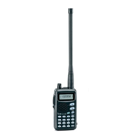
D Antenna CAUTION: Transmitting without an antenna may damage the transceiver. Insert the supplied antenna into the antenna connector and screw down the antenna as shown below. Keep the jack cover attached when jacks are not in use to avoid bad contacts from dust and moisture. ACCESSORY ATTACHMENT D Belt clip Conveniently attaches to your belt. -
Page 6: Panel Description
PANEL DESCRIPTION Panel description [DIAL] [PTT] Tx/Rx indicator [LIGHT] [ DIGIT KEYS] [ ENT( [MIC/SP] [ANT] Display [UP/DOWN] [SQL( SCAN) [PWR] [ CLR( DIAL/ÙÚ) [ ANL( REC) [ BANK( PLAY) [ FUNCTION] [ MR(... - Page 7 q LIGHT [LIGHT] (p. 10) Turns the light for display and keypad ON or OFF. w PTT SWITCH [PTT] (p. 11) Push and hold to transmit; release to receive. e TUNING DIAL [DIAL] (p. 8) Rotate [DIAL] to select the desired frequency. (default) Rotate [DIAL] to select the BANK number.
- Page 8 PANEL DESCRIPTION !0 CLR KEY [CLR (DIAL/YZ)] (continue) Push [CLR] to cancel the SCAN function. Push [CLR] to cancel the direct frequency enter- ing with digit key. Push [CLR] to turn the squelch level adjusting mode OFF. !1 ANL KEY [ANL (REC)] Push to turn the ANL function ON or OFF.
-
Page 9: Panel Description ............................................................... 2
• Adjustable level; 0 to 9 (p. 9) Push played memory or weather channel as a “TAG” channel. (p. 17) These functions available on the IC-A23 only. PANEL DESCRIPTION , then push [4 (CDI)] to select the CDI , then push [5 (DUP-W)] to set the du-... -
Page 10: Function Display
LOCK INDICATOR (p. 10) Appears while the lock function is in use. r DUPLEX INDICATOR (IC-A23 only) (p. 22) “DUP” appears when the duplex function is activated in NAV mode. “DUP” blinks while setting the duplex frequency. -
Page 11: Panel Description ........................................................ 2
VOR station or lead- ing away from the VOR station. !4 COURSE DEVIATION NEEDLES (IC-A23 only) (p. 22) Indicates the deviation between the desired course and your actual flying course every 2 degrees. -
Page 12: Basic Operation
Accessing 121.5 MHz emer- gency frequency The IC-A23 and IC-A5 can quickly access the 121.5 MHz emergency frequency. This function can be activated even when the key lock function is in use. q Push , then push [121.5] to call the emergency fre-... -
Page 13: Selecting A Weather Channel
Selecting a weather channel (U.S.A. version only) The U.S.A. version has VHF marine WX (weather) channel receiving capability for flight planning. q Push , then push [ENT (WX)] to select WX channel mode. • “WX--” and previously se- lected channel number ap- pears. -
Page 14: Lock Function
BASIC OPERATION Lock function The lock function prevents accidental frequency changes and accidental function activation. q Push , then push [KEY LOCK] to turn the function ON. w To turn the function OFF,repeat step q above. • “ ” disappears. Display backlighting Push [LIGHT] to turn the display backlighting ON or OFF. -
Page 15: Basic Operation .......................................................... 8
Receiving q Push [PWR] to turn the power ON. w Push [SQL], then turn the [DIAL] counterclockwise (or [Z] key) to select the squelch level [0]. e Push [Y]/[Z] key several times to adjust the audio level. r Push [SQL], then turn the [DIAL] clockwise (or [Y] key) until the noise is muted. -
Page 16: Memory Operation
MEMORY OPERATION Memory channel selection The transceiver has 200 memory channels for storage of often-used frequencies along with 6-character notes. q Push [MR] to select memory mode. • Memory BANK number and memory CH number appears. Using the [DIAL]: w Push [BANK], then rotate the [DIAL] to select the desired memory bank number, then push [BANK] (or [CLR]) to exit the bank selection mode. -
Page 17: Programming A Memory Channel
Programming a memory channel The transceiver has 200 (10 BANK x 20 CH) memory chan- nels for storage of often-used frequencies. q Push [CLR] to select Frequency mode, if necessary. w Select the desired frequency. • Push , then push [ENT (WX)] to select a weather channel.* •... -
Page 18: Memory Names
MEMORY OPERATION Memory names ï Programming memory names The memory channel can display a 6-character comment as well as a frequency. q Rotate the [DIAL] to select the desired frequency in Fre- quency mode. w Push , then push [MR]. e Rotate the [DIAL] to select the desired memory channel to be programmed. - Page 19 • EXAMPLE: Programming 125.000 MHz into memory BANK 0/ memory channel 15 with “AIR-23” as a comment. [CLR], [1], [2], [5], [ENT] [MR] [0], [0], [0],[2],[3] MEMORY OPERATION [F], [MR(MW)] [2], [2], [4], [4], [4], [4] [ENT] *NOTE: Push [BANK], then rotate the [DIAL] to select the BANK number, if desired.
-
Page 20: Scan Operation
SCAN OPERATION Scan types The U.S.A. version has 3 scan types to suit your needs. The non-U.S.A. versions have 2 scan types. COM BAND SCAN 108.00 118.00 136.975 Scan Jump MEMORY SCAN non-TAG channel Mch 2 Mch 4 Mch 6 Mch 1 Mch 7 non-TAG... -
Page 21: Weather Channel Scan
Weather channel scan (U.S.A. version only) q Push , then push [ENT (WX)] to select a weather channel. w Set squelch to the point where noise is just muted. e Push , then push [SQL (SCAN)] to start the scan. •... -
Page 22: Vor Navigation (Ic-A23 Only)
Course deviation needle NAV BAND (108.00–117.975 MHz) DVOR MODE Course indicator Push [F] then [q DVOR]. CDI MODE General VOR equipment Function display of the IC-A23 FROM Course indicator To-from flag indicator To-from flag indicator Push [F] then [r CDI]. -
Page 23: Vor Functions
◊ To select DVOR mode When entering the NAV band, 108.000–117.975 MHz, the IC-A23 selects DVOR mode automatically. To show your aircraft’s direction to (or from) the VOR station, push , then [1 (DVOR)]. -
Page 24: Flying To A Vor Station
VOR NAVIGATION Flying to a VOR station The IC-A23 shows the deviation from a VOR station. q Select a VOR station on your aeronautical chart and set the frequency of the station. • The course indicator indicates where you are located on a radial from the VOR station. - Page 25 THE AIRCRAFT IS ON COURSE THE AIRCRAFT IS OFF COURSE The course deviation indicator ap- pears when the aircraft is off course. In this example, the aircraft is 6 degrees off course to the left. The pilot must turn more than 6 degrees right to get back on course.
-
Page 26: Entering A Desired Course
VOR NAVIGATION Entering a desired course The IC-A23 shows not only the deviation from the VOR sta- tion but the deviation from the desired course. q Set the frequency for the desired VOR station. • To change the to-from flag, push (FROM)]. -
Page 27: Crosschecking Position
EXAMPLE: Entering the desired course bearing 89° to a VOR station. CROSSCHECKING POSITION VORTAC OLYMPIA 330 340 113.4 Ch 81 OLM 310 320 station VOR NAVIGATION 123.65 VORTAC SEATTLE 330 340 310 320 116.8 Ch 115 SEA Magnetic north station... -
Page 28: Duplex Operation
VOR NAVIGATION Duplex operation (U.S.A. version only) The duplex function allows you to call a flight service station while receiving a VOR station. The duplex function requires frequency programming for the flight service station in ad- vance. ◊ Programming a duplex frequency q Push [CLR] to select frequency mode. -
Page 29: Battery Packs
Charging precautions NEVER connect two or more chargers at the same time. Charging may not occur under temper- atures of 10°C (+50°F) or over temper- atures of 40°C (+104°F). When using BC-119: If the charge indicator flashes orange, vehicle bat- tery voltage is low and charging is not possible. - Page 30 Attach the battery pack to the transceiver. w Be sure to turn the transceiver power OFF. e Connect the Wall charger (BC-110A) or optional cable (CP-12L or OPC-254L) as shown below. • Charging period: 15 hours IC-A23/A5 with attached battery case AD-87A (optional)
-
Page 31: Battery Packs ........................................................... 25
About the battery pack D Operating period The operating period of the transceiver is 6 hours. • Operating periods are calibrated for the following conditions: at 25°C (77°F), Tx : Rx : standby = 5 : 5 : 90 D Battery pack life If your battery pack seems to have no capacity even after being fully charged, completely discharge it by leaving the power ON overnight. -
Page 32: Cloning
When cloning is finished, turn power OFF, then ON again to exit cloning mode. NOTE: DO NOT transfer the data from IC-A23 to IC-A5, when the data contains the NAV band data. In such case, cloning error may occur. -
Page 33: Troubleshooting
If your transceiver seems to be malfunctioning, please check the following points before sending it to a service center. PROBLEM No power comes on. • The battery is exhausted. • Bad connection for the battery pack. No sound comes from the •... -
Page 34: Specifications
SPECIFICATIONS D General • Frequency coverage (MHz): TX : IC-A23 only, IC-A5; 118.000 to 136.975 : U.S.A. version only. • Mode : 6K00A3E • Number of memory channels : 200 (10 BANK x 20 CH) • Acceptable power supply : 9.6 V DC nominal (negative ground) •... -
Page 35: Options
D Battery packs BP-200L Operating periods are calibrated for the following conditions: at 25°C (77°F), Tx (high power) : Rx : standby = 5 : 5 : 90 D Other options BC-110A WALL CHARGER (same as supplied. Depends on version) Used for regular charging of the connected battery pack. -
Page 36: Opc-967 Connection
D OPC-967 ( HEADSET ADAPTER) When using an optional headset, such as those from the David Clark Co. via the adapter transmitted voice to the headset for monitoring. (p. 9) IC-A23 IC-A5 connection the transceiver outputs your OPC-967 Clip the cable to the... -
Page 37: Quick Reference
QUICK REFERENCE Important operating instructions are summed up in this and the following page for your simple reference. By cutting along the line and folding on the dotted line, it will become a card sized operating guide which can easily be carried in a card case or wallet, etc. -
Page 38: Operation Guide
OPERATION GUIDE... - Page 39 Count on us! A-5665H-1EX Printed in Japan © 2000 Icom Inc. 6-9-16 Kamihigashi, Hirano-ku, Osaka 547-0002 Japan...
Need help?
Do you have a question about the IC-A23 and is the answer not in the manual?
Questions and answers
how do I get the antenna off my a23
The document does not provide specific instructions on how to remove the antenna from the Icom IC-A23. However, it warns that improper handling of the antenna connector could damage the transceiver’s front end.
This answer is automatically generated