
Subscribe to Our Youtube Channel
Related Manuals for Link-Belt PULSE


Summary of Contents for Link-Belt PULSE
- Page 1 Link‐Belt Pulse Calibration Manual (Level 2) Access on Cranes with Outrigger Sensors ® Link‐Belt is a registered trademark.
- Page 4 Link‐Belt Pulse Calibration Manual...
-
Page 5: Table Of Contents
Table Of Contents General Information ............... . Display Button Identification . - Page 6 Auxiliary Lifting Devices ..............Winch .
-
Page 7: General Information
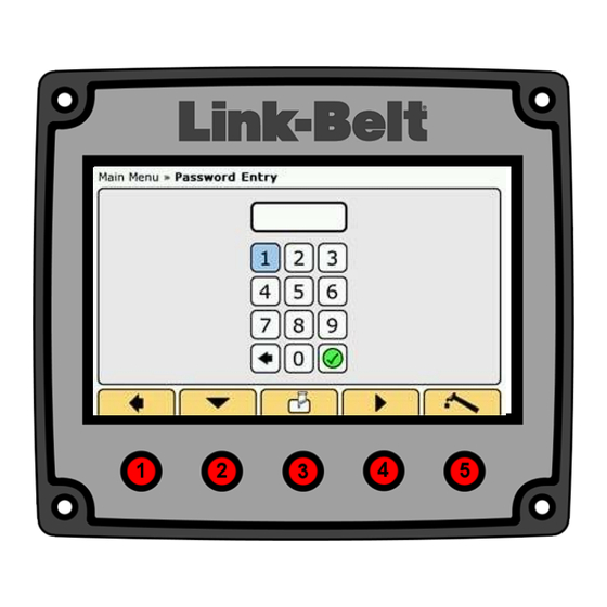
General Information Display Button Identification 1. Required Tools 1. The Buttons on the actual Pulse Display are not numbered, but for the purpose of this document, a. Test weights - [1 approximately 2,000 lb (907kg) Buttons 1 through 5, starting on the left, will be ref- and 1 approximately 10,000 lb (4 536kg)] b. -
Page 8: Calibration And Programming Procedures
Calibration And Programming Procedures 1. Calibration Mode Entry c. Use Buttons 2 and/or 4 to navigate to the first number of the Password and press Button 3 to enter the number. Follow this procedure for each number of the Password. Press Button 3 one more time when checkmark is highlighted. -
Page 9: Boom Length Calibration
Boom Length Calibration Zero Telescope Cylinder Calibration 1. Fully retract the boom. 4. Use Buttons 2 and/or 4 to navigate to Boom Length. 5. Press Button 3 to enter Boom Length. 2. In Access Level 2, use Buttons 2 and/or 4 to navig- ate to Calibration and Programming. - Page 10 CAUTION Manual mode is intended only for emergency operation. Improper operation of the boom in manual mode can cause major damage to the boom. Extend/Retract Switch Not Pinned Indicator Light 8. Pinned Indicator Light Latch Forward Indicator Light Pin/Unpin Switch 9.
- Page 11 14. Depending on the previous inputs, “Zero Tele- scope Cylinder Successful” or “Zero Telescope Cylinder Failure” should be shown. Note: If a “Zero Telescope Cylinder Failure” is shown when trying to zero the telescope cylin- der, confirm that the Manual Control Box is plugged in and the “PINNED and NOT LATCHED”...
-
Page 12: Calibrate Boom Length - Pat Reel Initial Setup
Calibrate Boom Length – PAT Reel Initial Setup 1. Remove cover from PAT reel. 2. Adjust soft stop on length potentiometer. 2-Gear Reeling Drum 3-Gear Reeling Drum a. Soft stop adjustment for 2-gear reel, use small b. Soft stop adjustment for 3-gear reel, use small screwdriver and rotate potentiometer counter- screwdriver and rotate potentiometer clock- clockwise until potentiometer stops. -
Page 13: Calibrate Boom Length - Pin And Latching Booms
Calibrate Boom Length - Pin And Latching Booms 4. Fully retract the boom for the first calibration point. Note: Adjust soft stop on PAT reel first. Refer to With the boom fully retracted and in the “PINNED “Calibrate Boom Length-PAT Reel Initial Setup”. and LATCHED”... -
Page 14: Calibrate Boom Length - Full Power Booms
Calibrate Boom Length – Full Power Booms 4. Fully retract the boom for the first calibration point - Note: Adjust soft stop on PAT reel first. Refer to with the boom fully retracted, press Button 3 which “Calibrate Boom Length-PAT Reel Initial Setup”. will place a green checkmark at the Set Fully Re- tracted position as in the example above. -
Page 15: Boom Angle Calibration
Boom Angle Calibration 1. In Access Level 2, Calibration and Programming, 6. A green checkmark will appear indicating position use Buttons 2 and/or 4 to navigate to Boom Angle. has been calibrated. 7. Raise the boom to 80 degrees, verifying with a di- 2. - Page 16 10. Enter actual angle value. I.E. 80 degrees. Use But- tons 2 and/or 4 to navigate to the first number and press Button 3 to enter the number. Repeat for the second number. 11. Use Buttons 2 and/or 4 to navigate to the green checkmark.
-
Page 17: Swing Angle Calibration
Swing Angle Calibration 1. In Access Level 2, Calibration and Programming, 6. A green checkmark will appear indicating the 0° use Buttons 2 and/or 4 to navigate to Swing Angle. position has been calibrated. 7. Release the travel swing lock. 2. -
Page 18: Pressure Programming
Pressure Programming Program Pressure Transducers 1. In Access Level 2, Calibration and Programming, 7. A green checkmark will appear indicating piston use Buttons 2 and/or 4 to navigate to Pressure. pressure transducer has been programmed. The 2. Electrically disconnect both pressure transducers piston pressure transducer readout should now re- from the system. -
Page 19: Reset Pressure Transducers
Reset Pressure Transducers This is used to reset the CAN ID to factory default. If this procedure is used, the CAN ID’s must be repro‐ grammed by repeating the previous procedures, “Program Pressure Transducers”. 3. Use Buttons 2 and/or 4 to navigate to Reset Piston Pressure Sensor. -
Page 20: Outrigger Programming And Calibration
Outrigger Programming And Calibration This is used to program and calibrate the outrigger sensors. 1. In Access Level 2, Calibration and Programming, use Buttons 2 and/or 4 to navigate to Outriggers. Use Buttons 2 and/or 4 to navigate to “Pro‐ gram Front Left”. - Page 21 beams.
- Page 22 4. Use the following procedures to reset the outrigger sensors if any outrigger sensor system faults are present. Note: One can reset individual or all sensors based on whether or not the sensor(s) is/are con- nected. If a sensor is connected it will be reset. a.
-
Page 23: Hydraulic Fly Angle Sensor Calibration
Hydraulic Fly Angle Sensor Calibration 1. In Access Level 2, Calibration and Programming, use Buttons 2 and/or 4 to navigate to Fly Angle. 2. Press Button 3 to enter Fly Angle. 6. A green checkmark will appear indicating the 2° Angle has been calibrated. - Page 24 8. Use Buttons 2 and/or 4 to navigate to Set 2° Fly 10. Confirm and then enter the actual boom angle Angle at Max Boom Angle. value. (I.E. 80°.) Use Buttons 2 and/or 4 to navig- 9. Press Button 3 to enter Set 2°Fly Angle at Max ate to the first number and press Button 3 to enter Boom Angle.
-
Page 25: Main Winch Friction Calibration
Main Winch Friction Calibration See Appendix A for Dynamic and Friction Calibration procedures for cranes requiring these procedures. 4. Use Buttons 2 and/or 4 to navigate to Main Winch. 5. Press Button 3 to enter Main Winch. 1. Ensure the computer system is fully operational, in working mode, and with a fully functional ATB sys- tem. - Page 26 8. Calibrate Short Boom Friction screen should ap- higher piston pressures. Adjust sliders until the cor- pear. rect weight is displayed. 9. Fully retract the boom and position to 0 degree Note: Static load adjustment will not show cor- boom angle. rection until Step 14 is completed.
- Page 27 25. Wait at least 30 seconds for the accurate load weight. (If an adjustment is made to the friction modifier sliders, slightly engage the boom hoist hy- draulics again and wait at least 30 seconds for the accurate load weight.) Use the number on the left for lower piston pressures and the number on the right for higher piston pressures.
- Page 28 35. Repeat the complete “Main Winch Friction Calibra- tion” procedures given previously while lifting the test weight of approximately 10,000 lb (4 536kg) in place of the test weight of approximately 2,000 lb (907kg), where applicable within the load rating charts.
-
Page 29: Auxiliary Winch Friction Calibration
Auxiliary Winch Friction Calibration See Appendix A for Dynamic and Friction Calibration procedures for cranes requiring these procedures. 5. Use Buttons 2 and/or 4 to navigate to Auxiliary Winch. 6. Press Button 3 to enter Auxiliary Winch. 1. Ensure the computer system is fully operational, in working mode, and with a fully functional ATB sys- tem. - Page 30 10. With the test weight hanging in a “static” state, use 16. Press Button 3 to select the chosen setting. Buttons 2 and/or 4 to adjust the static load to actual 17. At each friction modifier angle, lift the load and wait approximately 30 seconds for the accurate load load on the hook.
-
Page 31: Bias And Slope Sliders Explanation
Bias And Slope Sliders Explanation Always start at a high boom angle and adjust the Bias to achieve actual load on hook. The Bias slider will move the entire Calibration Target UP or DOWN as shown below. I.E. - Actual load on hook is 8,000 lb (3 629kg) and the Calibration Target is at 6,500 lb (2 948kg), increase the slider value until the Calibration Target of 8,000 lb (3 629kg) is achieved. -
Page 32: Fly Weight Calibration (Fly Erected)
Fly Weight Calibration (Fly Erected) 1. Ensure the computer system is fully operational, in working mode, and with a fully functional anti-two block system. Setup crane on fully extended out- riggers and select boom mode to allow full exten- sion of all boom sections. Configure the crane preferably with full counterweight. - Page 33 11. Use Buttons 2 and/or 4 to move the highlighted po- sition (blue) to the appropriate adjustment slider. 12. Press Button 3 to activate the slider, which will turn the slider green. 13. With the test weight hanging in a “static” state, use Buttons 2 and/or 4 to adjust the static load to actual load on hook.
-
Page 34: Fly Weight Calibration (Fly Stowed)
Fly Weight Calibration (Fly Stowed) 1. Ensure the computer system is fully operational, in working mode, and with a fully functional anti-two block system. Setup crane on fully extended out- riggers and select boom mode to allow full exten- sion of all boom sections. Configure the crane preferably with full counterweight. - Page 35 11. Use Buttons 2 and/or 4 to move the highlighted po- sition (blue) to the appropriate adjustment slider. 12. Press Button 3 to activate the slider, which will turn the slider green. 13. With the test weight hanging in a “static” state, use Buttons 2 and/or 4 to adjust the static load to actual load on hook.
-
Page 36: Diagnostics
Diagnostics 1. In Access Level 2, use Buttons 2 and/or 4 to navig- 3. The CAN Viewer allows the operator to view the ate to Diagnostics. CAN traffic on either CAN Bus 1, 2, or 3. 2. Press Button 3 to enter Diagnostics. CAN Viewer 4. -
Page 37: Active System Faults
Active System Faults System Fault Log 1. In Access Level 2, Diagnostics, use Buttons 2 and/ 3. In Access Level 2, Diagnostics, use Buttons 2 and/ or 4 to navigate to Active System Faults. or 4 to navigate to System Fault Log. 2. -
Page 38: Boom Telescope Diagnostics
Boom Telescope Diagnostics Primary Telescope Cylinder Length – * - indicates LTC controller is currently using 1. In Access Level 2, Diagnostics, use Buttons 2 and/ encoder or 4 to navigate to Boom Telescope. k. Secondary Telescope Cylinder Length – 2. -
Page 39: Outrigger Position Diagnostics
Outrigger Position Diagnostics 2. Press Button 3 to enter Outrigger Position. a. This screen will show actual length and posi- 1. In Access Level 2, Diagnostics, use Buttons 2 and/ tion readings of each outrigger beam. or 4 to navigate to Outrigger Position. -
Page 40: Sensor Data
Sensor Data e. Piston Pressure Rod Pressure Active Sensor Values – Shows a summary of all g. Cylinder Length Primary sensors in the system. h. Cylinder Length Secondary 1. In Access Level 2, Diagnostics, use Buttons 2 and/ Boom Controller Length or 4 to navigate to Sensor Data. -
Page 41: Setup
Setup Counterweight Crane dependant option – enables/disables counter- weight selections. 1. In Access Level 2, use Buttons 2 and/or 4 to navig- ate to Setup. 2. Press Button 3 to enter Setup. 1. In Access Level 2, Setup, Enable Options, use But- tons 2 and/or 4 to navigate to Counterweight. -
Page 42: Auxiliary Lifting Devices
3. Use Buttons 2 and/or 4 to navigate to the desired Auxiliary Lifting Devices device selection. 4. Press Button 3 to enable the desired selection. This enables/disables Auxiliary Head and Fly Selec- (Pressing Button 3 again will disable the selection.) tions. -
Page 43: Winch
3. Use Buttons 2 or 4 to navigate to desired device se- Winch lection. a. Front Winch This enables/disables Winch and First Layer/Third b. Rear Winch Wrap Selections. First Layer/Third Wrap Without Function Kick- 1. In Access Level 2, Setup, Enable Options, use But- out (FKO) tons 2 and/or 4 to navigate to Winch. -
Page 44: Misc
2. Press Button 3 to enter Misc. Misc 3. Use Buttons 2 and/or 4 to navigate to desired 1. In Access Level 2, Setup, Enable Options, use But- device selection. tons 2 and/or 4 to navigate to Misc. a. Wind Speed – enables/disables wind speed indication b. -
Page 45: Front Winch Rope Capacity
Front Winch Rope Capacity Rear Winch Rope Capacity 1. In Access Level 2, Setup, use Buttons 2 and/or 4 to 1. In Access Level 2, Setup, use Buttons 2 and/or 4 to navigate to Front Winch Rope Capacity. navigate to Rear Winch Rope Capacity. 2. -
Page 46: About
2. Press Button 3 to enter About. About a. Display Version b. RCL Version 1. In Access Level 2, use Buttons 2 and/or 4 to navig- LTC Version ate to About. d. Crane Serial e. Load Chart Display Crane Type g. -
Page 47: Friction And Dynamic Calibration
Appendix A Friction And Dynamic Calibration 1. Ensure the computer system is fully operational, in working mode, and with a fully functional ATB sys- tem. Setup crane on fully extended outriggers, and select boom mode to allow full extension of all boom sections. - Page 48 piston pressures and the number on the right for...
- Page 49 higher piston pressures. Adjust sliders until the cor- 26. If a boom angle is unattainable and the load is rect weight is displayed. between two friction modifier angles, the sliders for the higher and lower angle must both be adjusted Note: Static load adjustment will not show cor- to smooth out the curve.
- Page 50 49. If a boom angle is unattainable and the load is between two friction modifier angles, the sliders for the higher and lower angle must be both adjusted to smooth out the curve. 50. The load reading must be equal to actual load to +10% over actual load.
- Page 51 69. Press Button 1 to return to Calibrate Boom Up Fric- 90. Ensure the boom is fully extended. tion. 91. Lift the test weight of approximately 2,000 lb (907kg). 70. Use Buttons 2 and/or 4 to navigate to Calibrate Me- 92.
- Page 52 98. Long Boom (fully extended boom length) screens. 99. Repeat the complete procedures above lifting the test weight of approximately 10,000 lb (4 536kg), in place of the weight of approximately 2,000 lb (907kg), where applicable within the load rating charts.
-
Page 53: Hed Programming Instructions
Appendix B HED Programming Instructions When arriving at the crane, the laptop display to be used should look similar to the above. 1. Use the left mouse button and double click on the HED file to be programmed to the crane RCL computer. WinZip should open and look similar to the above. - Page 54 3. Click the “Desktop” icon. 4. Click the “Extract” button. A window should open and the screen should look similar to the above. 5. Use the left mouse button and double click on the “Pulse Software” icon.
- Page 55 A second window should open and the screen should look similar to the above. 6. Use the left mouse button and double click the “HED” folder. 7. Use the left mouse button and double click the “Shortcut to Files_Digital” folder.
- Page 56 8. Use the right mouse button and click on the “romfs.jffs2” file. 9. Use the left mouse button and click on the “Copy” option. 10. Use the right mouse button and click in the “Files_Digital” window. 11. Use the left mouse button and click the “Paste” option.
- Page 57 12. Left click on the “Copy and Replace” option. File preparation is complete. 13. Use the left mouse button and click on the “Back” arrow button.
- Page 58 14. Left click on the “HED Programmer II” file. The “HED Display Device Programmer II” window should open as shown above.
- Page 59 15. Turn the crane ignition switch off. 16. Connect the laptop to the USB Programming Connector. 17. Turn the crane ignition switch on. An “AutoPlay” window should open automatically as shown above. 18. Close the “AutoPlay” window by left clicking the “X” button.
- Page 60 19. Use the left mouse button to click on “HED device –disk E:” 20. Use the left mouse button to click the single right arrow button. 21. Use the left mouse button to click on the box next to “romfs.jffs2”. This will place a check mark in the box. If programming a new display that has not been programmed before, also place a check in the box next to “logo”.
- Page 61 22. Use the left mouse button to click on the “Start” button.
- Page 62 After clicking the “Start” button, programming should begin. Do not allow the computer to “go to sleep”. The status bar should begin to move. Once “Request completed.” appears at the bottom of the screen, the programming process is complete. 23. Turn the crane ignition switch off, remove the RCL Display fuse, close the “HED Display Device Programmer II” program, and disconnect the USB cable.
-
Page 63: Ecm Programming Instructions
Appendix C ECM Programming Instructions 1. Before updating any software, always record ALL friction slider values. These values can be entered after updating software to minimize the time re- quired for calibration. The “.srz” file will be the file to program the LTC Elec‐ tronic Control Module (ECM). - Page 64 CAN 1 CAN 2 8. Turn crane ignition switch to the “ON” position. (The crane engine does not have to be started.) 9. Start the “MotoUpdate” software (Desktop Icon or through the Start – All Programs Menu). 10. Select the correct programming location (Blank, RCL, or LTC).
- Page 65 17. When programming is complete, “Programming 13. Click the “Program SRZ” button. Successful” message should appear. 14. Using the “BLANK” programming location will set the “CityID” of the ECM. Confirm all connections are connected into the correct programming port when using the “BLANK” command. a.
- Page 66 22. Program will search for the ECM, connect to the ECM, and begin loading the selected file. 20. Select file to be programmed. 23. When programming is complete, “Programming Successful” message should appear. 21. Click “Open”.
- Page 67 24. Select the programming location for “RCL”. 26. Select the file to be programmed. a. FIELD – use this file to update software. No cal- ibration required. b. PASSWORDRESET – use this file to reset the default factory passwords. FACTORY – use this file when directed to do so by the version description.
- Page 68 28. Program will search for the ECM, connect to the ECM, and begin loading the selected file. 34. Press button 1 to enter the Main Menu. 29. When programming is complete “Programming Successful” message should appear. 30. Turn crane ignition switch to the “OFF” position. 31.
- Page 69 ORY” or “FIELD”) installed, perform necessary pro- cedures to complete the installation. a. FIELD version – no calibration required b. FACTORY version – full calibration required. Refer to procedures given previously in this Pulse Calibration Manual. 39. Turn crane ignition switch to the “OFF” position.
Need help?
Do you have a question about the PULSE and is the answer not in the manual?
Questions and answers
How to enter access 2 8090 link belt