
Related Manuals for Sigicom INFRA C22


Summary of Contents for Sigicom INFRA C22
- Page 1 INFRA C22 Wireless Vibration Monitor Art no. 080-05222-0 Manual ver. K Valid for firmware 2.3.0 Manual Copyright © Sigicom AB 2020 Art.no. ML089-05222-0En...
- Page 2 Only use batteries and power supplies provided or recommended by 8 Accessories Sigicom, see chapter • Do not use C22 batteries in other products than applicable Sigicom products. • A power source connected to the C22 must not be able to supply more than 20V and 3A.
- Page 3 Scrapped equipment should be sent back to the manufacturer of the equipment (Sigicom AB) for proper handling according to the WEEE directive. • Sigicom uses a certified local partner for recycling of scrapped equipment. The batteries used in this equipment falls under the Battery Directive 2006/66/EC: •...
-
Page 4: Table Of Contents
Table of Contents Introduction ..................7 1.1. INFRA System ................. 7 1.2. INFRA C22 Vibration Monitor ..........7 1.3. INFRA C22 Enclosure ............. 8 1.4. Unpacking and Parts Identification .......... 9 Product Description ................. 10 2.1. Keypad ................... 10 2.2. - Page 5 GPS position ................40 6.3. GPS time synchronization ............41 6.4. Time Synchronization through Internet ......... 41 6.5. Daylight Saving Time ............41 Technical Specifications ..............43 Accessories ..................44 Maintenance and Calibration ............45 Copyright © Sigicom AB 2020...
- Page 6 Appendix G. Standards with Frequency Weighting ....... 67 Appendix H. British Standard BS 6841 (VDV) ........70 Appendix I. Set another APN (external SIM) ........72 Developed and manufactured by: Sigicom AB Glasfibergatan 8 SE – 124 45 Älvsjö, Sweden Support: support@sigicom.com Copyright © Sigicom AB 2020...
-
Page 7: Introduction
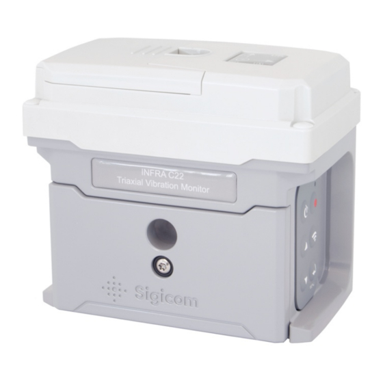
Manual communication is performed by the operator. • At scheduled communication. 1.2. INFRA C22 Vibration Monitor The C22 instrument is a complete triaxial wireless vibration monitor measuring in three directions, vertical, longitudinal, and traverse. It consists of vibration sensor elements, analog measuring electronics, analog-digital converters, an embedded microcontroller/DSP for digital signal processing etc., a small color display, a six-button keypad, a... -
Page 8: Infra C22 Enclosure
1.3. INFRA C22 Enclosure The enclosure base is milled out of solid aluminum and includes: • A horizontal hole for wall-mounting (M6 or ¼” bolt). • A vertical hole for floor-mounting (M6 or ¼” bolt). • A front lid covering the two batteries. -
Page 9: Unpacking And Parts Identification
1.4. Unpacking and Parts Identification The INFRA C22 Vibration Monitor has been shipped in protective packaging. Please keep this and use it when transporting your equipment. Verify the package content with the following list: • C22 Vibration Monitor instrument. •... -
Page 10: Product Description
Menu / Enter / Acknowledge / Activate For more information about operation of the graphical user interface, see chapter 5 Operation. Note! The LED indicator (the green circle in the picture above) is only used at firmware upgrade. Copyright © Sigicom AB 2020... -
Page 11: Display
DATA: Measurement standard. Vibration data; interval (INTV) or transient (EVT) values in three directions. Live values for three directions = maximum over the last three seconds. MONITORING status. GPS and COMMUNICATION status. ERRORS and WARNINGS Copyright © Sigicom AB 2020... -
Page 12: Batteries
When set through the graphical user interface, the memory card can be accessible as a Windows drive via the USB interface. See section 5.8.5. Firmware upgrade is normally performed remotely via INFRA Net but may also be done via the USB interface. See section 5.8.6. Copyright © Sigicom AB 2020... -
Page 13: Memory Card
If the memory card is unintentionally missing (or corrupt), an error message will be displayed at start-up. Please contact Sigicom Support for guidance regarding memory card formatting or other memory card issues. Note! Only use a memory card approved by Sigicom. - Page 14 Note! The PIN-code lock of the removable mini-SIM card must be deactivated before use in C22. Contact your network provider for pin-code lock deactivation. For activation or deactivation of the embedded SIM card, please contact Sigicom Support. Copyright © Sigicom AB 2020...
-
Page 15: Measuring Parts
The main processor of the C22 is a combined general processor and a digital signal processor (DSP). The DSP part of the processor filters, compensates and detects the signals according to the selected measurement standard Copyright © Sigicom AB 2020... -
Page 16: Measuring Logic
The three normal values, V, L and T, are always stored, and are always un- weighted, even if frequency weighting is active This is different compared to e.g. INFRA C12. Copyright © Sigicom AB 2020... - Page 17 The limit here is equal to the lowest possible threshold for the chosen standard e.g. 0.4 mm/s (0.02 in/s) for standards with level range 250 mm/s, and 0.04 mm/s (0.002 in/s) for standards with level range 25 mm/s. Copyright © Sigicom AB 2020...
-
Page 18: Transient Recording
In this way INFRA Net can indicate possible overload in its interval and transient data reports. Overload is indicated in the display with a “>” before the value. Copyright © Sigicom AB 2020... -
Page 19: Data Storage
3.3. Data Storage C22 follows the data storage model for the new generation of Sigicom’s INFRA instruments. Although data files are accessible through the USB interface (see section 5.8.5), data is only readable after post-processing through INFRA Net. Transient Data 3.3.1. -
Page 20: Configuration And Installation
4. Configuration and Installation 4.1. Configurations and Settings The customer’s INFRA Net account is pre-set from Sigicom prior to delivery and cannot be changed by the customer. Contact Sigicom Support if this needs to be changed. INFRA Net Communication Schedule 4.1.1. -
Page 21: Factory Default Settings
Make sure that the C22 is firmly attached and aligned (plumb and level). For correct measuring results, the mounting angle of the instrument must not exceed 5º relative to the horizontal plane. Refer to Sigicom product catalog for more information on mounting solutions. -
Page 22: Site Startup Check
4.3. Site Startup Check After mounting, it is recommended to start the instrument and check: • Battery level • Clock set • INFRA Net communication • Monitoring Copyright © Sigicom AB 2020... -
Page 23: Operation
Sensor test failed, or the alignment of the sensor is not horizontal enough. After transition into monitoring mode, the instrument will communicate to INFRA Net and transmit its status. In previous INFRA systems, Monitoring is called registration (REGON). Copyright © Sigicom AB 2020... -
Page 24: Sensor Test
If the instrument is recording when monitoring off is selected, the recording will be completed before monitoring is stopped. Once monitoring is stopped, the instrument will communicate to INFRA Net and update the instrument’s new status and data. Copyright © Sigicom AB 2020... -
Page 25: Infra Net Communication
Manual INFRA Net Communication 5.4.2. Manual communication can be intiated from the communication screen. Press to enter this screen, and then press again to start the communication. The communication process is displayed on the screen: Copyright © Sigicom AB 2020... -
Page 26: More Communication Information
When the batteries are completely discharged, monitoring will stop and the C22 will turn off. If power was accidentally lost while in monitoring mode (e.g. if the batteries were improperly removed), the C22 will restart monitoring when new or recharged batteries are reinserted. Copyright © Sigicom AB 2020... -
Page 27: Removal And Replacement Of Li-Ion Batteries
Turn the battery lock lever to the other side and remove/replace the second battery. • Reset the lock lever in its middle position for the lid to fit. • Replace the front lid using a Torx T20 driver. Figure 5. Instrument with front lid removed Copyright © Sigicom AB 2020... -
Page 28: Gui Menu
To view and possibly change the monitoring parameters, select “Monitoring config”: → Monitoring config Frequency weight parameter may also be available, as an additional option, depending on selected standard. to select parameter, and to enter the parameter settings screen. Copyright © Sigicom AB 2020... -
Page 29: Communication Mode
Normal mode: Internet and INFRA Net is available. • Flight mode: Internet and INFRA Net communication is disabled. Flight mode is indicated on the main screen with an airplane symbol: Set communication mode by pressing: → Settings and actions → Communication mode. Copyright © Sigicom AB 2020... -
Page 30: Clock Set
Note! C22 will reboot after the clock is changed. Clock Format 5.8.4. Time can be displayed in either 12- or 24-hour format, which is configured by this selection. This configuration is only for the instrument, INFRA Net is not affected by this. Copyright © Sigicom AB 2020... -
Page 31: Usb Memory Interface Mode
The microSD memory should now appear as a removable drive in the file system of the PC. When finished command the PC to eject the removable disc. Disconnect the USB connector from the instrument and it will reboot automatically. Copyright © Sigicom AB 2020... -
Page 32: Firmware Upgrade
This section describes how to upgrade to latest FW version when the C22 is in the office. To upgrade a C22 which is monitoring out in the field (so called Remote firmware upgrade), see section 5.10.1. The latest FW release is available for download from the Sigicom Support page: http://support.sigicom.com/infra/index.html Note! Monitoring must be OFF, and communication mode set to Flight mode (see section 5.8.2), to perform a firmware upgrade. - Page 33 The LED is positioned just above the REC-key on the keypad. Note! FW in green; if it is in yellow and without a frame the files are in downloading state. Copyright © Sigicom AB 2020...
-
Page 34: Errors And Warnings
Errors are in red text, and warnings in orange. If there are several errors, use the arrow keys to scroll between them. Each individual error code can be acknowledged / cleared with the key. A list of errors and warnings is presented in Appendix E. Copyright © Sigicom AB 2020... -
Page 35: Power Off And Reboot
→ Settings and actions → Power off / Reboot. Note! Monitoring must be OFF when doing Power off or Reboot. Select either Power off or Reboot in the list and click If none of the two selections is wanted, back out with Copyright © Sigicom AB 2020... -
Page 36: Gui Passcode
(or not entered at all), the C22 GUI will be opened in a ‘view- only’ mode. All settings and actions (including monitoring start) are prohibited. An active passcode may be deactivated in the following way: → Settings and actions → GUI Passcode. Copyright © Sigicom AB 2020... -
Page 37: Infra Net Remote Control
3. Use INFRA Net to change parameter settings. 4. Perform a manual communication again on the C22 to read the new change request. The changes will then be performed. For further information about INFRA Net remote control, see INFRA Net Hardware manual. Copyright © Sigicom AB 2020... -
Page 38: Remote Firmware Upgrade
Hardware tab) Special commands → Remote Reboot followed by Manage changes → Commit. The data logger will perform the reboot at the next communication. It may take several minutes until the firmware files have been downloaded. Copyright © Sigicom AB 2020... -
Page 39: Remote Shut Down
Please select (in INFRA Net – Hardware tab) Special commands → Remote Update GPS Position followed by Manage changes → Commit. The C22 will perform the update at the next communication. First a controlled “Stop Monitoring” will be performed. Copyright © Sigicom AB 2020... -
Page 40: Other Functions
Red, when no GPS position is received after latest Monitoring On • Yellow, when a GPS position is received (accuracy > 20 meters) • Green, when a GPS position is received (accuracy < 20 meters) Copyright © Sigicom AB 2020... -
Page 41: Gps Time Synchronization
C22:s are placed with a distance of at least 50 meter between them, and that their Trigger level is so low that they triggers a transient each. Please contact Sigicom for further details of using this function. - Page 42 All data from C22 is time stamped with UTC time. Daylight Saving Time only affects the presentation of time. Copyright © Sigicom AB 2020...
-
Page 43: Technical Specifications
Static pressure: 101.3 kPa (14.7 psi) Accuracy: Noise and interference according to EMC demands in IEC61326-1:2006. Transient low-pass filter characteristics: - 0.5 dB at 467Hz, -3dB at 627Hz. Operations temp: -20°C to +50°C (-4°F to 122°F) Copyright © Sigicom AB 2020... -
Page 44: Accessories
Socket wrench 10 mm with handle, part number 080-01893-0 • Hex screwdriver 3 mm (for plastic antenna cover), part number 080-01894-0 • Transport case INFRA C2x, part number 080-01888-0 See latest INFRA product catalogue for a complete list of accessories and more details. Copyright © Sigicom AB 2020... -
Page 45: Maintenance And Calibration
If the backup battery drops below 2.6 V, a warning message will be communicated. For replacement of the backup battery, send the instrument to Sigicom. • If repair is required, please contact Sigicom prior to sending the instrument in for repair. Copyright © Sigicom AB 2020... -
Page 46: Contact And Support
SE-12545 ÄLVSJÖ Sweden Phone: +46 8 4499750 Email: info@sigicom.com USA: Sigicom Inc. 2636 Midpoint Drive Ste B Fort Collins, CO 80525 Phone: 970-493-1552 Email: info@sigicom.com World-wide Support: Phone: +46 8 44 99 770 Email: support@sigicom.com Copyright © Sigicom AB 2020... -
Page 47: Appendix A. Battery Level Limits
Service messages are sent when the SOC level falls below the BAT LOW or BAT CRITICAL levels. For replacement of the backup battery, send the instrument to Sigicom. SOC = State-Of-Charge (a combined state of charge of the two batteries). -
Page 48: Appendix B. Li-Ion Battery Transport
Transport by Air is prohibited according to the IATA Special Provision A154. • Follow safety instruction for Li-Ion batteries in the beginning of this manual. • Call Sigicom for consultation before any transportation. Note! Worn out batteries are forbidden in air transport. Copyright © Sigicom AB 2020... -
Page 49: Appendix C. Safe Handling Of Li-Ion Batteries
• Place the safety instruction easily seen in all sites where batteries are handled. • Inform personnel about the instruction. • Report all safety related events to management. Reference: http://batteryuniversity.com/learn/article/safety_concerns_with_li_ion Copyright © Sigicom AB 2020... -
Page 50: Appendix D. In Case Of Li-Ion Battery Fire
COMBUSTABLE MATERIAL PLACE THE BATTERY IN SAND FILLED BUCKET, PLACE OUTSIDE IF POSSIBLE USE FIRE EXTINGUISHER WATER IS OK IF NO OTHER KIND OF FIRE EXTINGUISHER IS AVAILABLE PUT SEEMINGLY BURNED-OUT BATTERY OUTSIDE FOR A TIME Copyright © Sigicom AB 2020... -
Page 51: Appendix E. Errors And Warnings
E100/1 Temperature alarms Cool down the instrument E102 Instrument humidity warning Check that all screws of the instrument lid are tightened Is set if instrument time differs two seconds or more from correct time, see section 5.8.3 Copyright © Sigicom AB 2020... - Page 52 Connect to the server so the files SD-card is full can be upload E115 Slow file opening Format the SD-card E116 Connect to the server so the files SD-card is almost full can be upload Copyright © Sigicom AB 2020...
-
Page 53: Appendix F. Measurement Standards
ISO 10816-2 200 mm/s RMS 1s Frequency: calculated frequency is sent in additional interval channels. Resultant: a calculated resultant value is sent as an additional interval channel. Resultant is only calculated when frequency weighting is OFF. Copyright © Sigicom AB 2020... - Page 54 5 – 150 Hz S28A SN 640312a 250 mm/s 5 – 150 Hz S28B SN 640312a 25 mm/s 1 – 300 Hz S30A BS 7385 250 mm/s 1 – 300 Hz S30B BS 7385 25 mm/s Copyright © Sigicom AB 2020...
- Page 55 1 – 100 Hz S46B SBR-A 25 mm/s 1 – 80 Hz SBR-B 20 mm/s Comfort RMS 125ms 2 – 250 Hz Toronto 250 mm/s bylaw 214 1 – 100 Hz Toronto 250 mm/s bylaw 214 Copyright © Sigicom AB 2020...
- Page 56 250 mm/s 1 – 315 Hz S60B NCh 3577 25 mm/s S70A BS 6841 125 m/s (VDV) S70B BS 6841 12.5 m/s (VDV) Different depending on vertical or horizontal. See Appendix H for a detailed description Copyright © Sigicom AB 2020...
- Page 57 Vibration och stöt – Mätning och riktvärden för bedömning av komfort i byggnader. Level and frequency ranges: 20 mm/s, RMS, 1-80 Hz. Filtered according to ISO 2631-2, time constant 1 s. Max resolution in presentation: 0.005 mm/s RMS and 3 significant digits. Copyright © Sigicom AB 2020...
- Page 58 Mechanical vibration and shock – Measurement and evaluation of shock and vibration effects on sensitive equipment in buildings. Level and frequency ranges: 125 m/s , 5-300 Hz. Max resolution in presentation: 0.01 m/s and 3 significant digits. 0.1 – 110 m/s Threshold range: Copyright © Sigicom AB 2020...
- Page 59 Vibrasjoner og støt - Måling av svingehastighet og beregning av veiledende grenseverdier for å unngå skade på byggverk. Level and frequency ranges: 250 mm/s, 5-300 Hz. Max resolution in presentation: 0.05 mm/s and 3 significant digits. 0.4 – 220 mm/s. Threshold range: Copyright © Sigicom AB 2020...
- Page 60 Max resolution in presentation: 0.005 mm/s and 3 significant digits. 0.04 – 22 mm/s. Threshold range: 27. ISO 2631-2 Human exposure to mechanical vibration and shock. Level and frequency ranges: 20 mm/s, RMS, 1-80 Hz. Copyright © Sigicom AB 2020...
- Page 61 0.04 – 22 mm/s. Threshold range: 33. ANSI S2.71 Guide to the Evaluation of Human Exposure to Vibration in Buildings. Level and frequency ranges: 0.8 in/s, RMS, 1-80 Hz. Filtered according to ISO 2631-2, time constant 1 s. Copyright © Sigicom AB 2020...
- Page 62 0.4 – 220 mm/s. Threshold range: 41. ICPE-Circ86 French standard ICPE Circulaire du 23/07/86. Level and frequency ranges: 25 mm/s, 1-150 Hz. Max resolution in presentation: 0.005 mm/s and 3 significant digits. 0.04 – 22 mm/s. Threshold range: Copyright © Sigicom AB 2020...
- Page 63 Max resolution in presentation: 0.05 mm/s and 3 significant digits. 0.4 – 220 mm/s. Threshold range: 46B. SBR-A Level and frequency ranges: 25 mm/s, 1-100 Hz. Max resolution in presentation: 0.005 mm/s and 3 significant digits. Copyright © Sigicom AB 2020...
- Page 64 Threshold range: 53A. Geophone Unfiltered geophone signal. Upper frequency limit 500 Hz. Level and frequency ranges: 250 mm/s, 5-500 Hz. Max resolution in presentation: 0.05 mm/s and 3 significant digits. 0.4 – 220 mm/s. Threshold range: Copyright © Sigicom AB 2020...
- Page 65 Federal Transport Administration (USA) Level and frequency ranges: 50 - 118 dB (rel. 10 in/s), RMS, 1-80 Hz. Filtered according to ISO 2631-2, time constant 1 s. Max resolution in presentation: 0.1 dB and 3 significant digits. Copyright © Sigicom AB 2020...
- Page 66 Acceleration standard including channels for VDV (Vibration Dose Value). See Appendix H for further description. Level and frequency ranges: 12.5 m/s 1.75 Max resolution in presentation: 10 and 3 significant digits. 0.04 – 11 m/s 1.75 Threshold range: Copyright © Sigicom AB 2020...
-
Page 67: Appendix G. Standards With Frequency Weighting
Drywall and Plaster, see Figure G1: • (4 – 15 Hz) Drywall: 0.75 in/s • (2.6 – 10 Hz) Plaster: 0.50 in/s Figure G1. Frequency weighting curves for the standards S51A and S51B (ISEE Seismograph). Copyright © Sigicom AB 2020... - Page 68 (peak) is greater than 1.0 in/s and its frequency is in the range 2.6 - 10 Hz • a signal (peak) is greater than 4.0 in/s and its frequency is 40 Hz (or higher) Copyright © Sigicom AB 2020...
- Page 69 Figure G2. Figure G2. Frequency weighting curves for the standards S18A and S18B (DIN 4150-3). This figure is copied from a Transient report in INFRA Net, where the different standard’s frequency weighting curves can be displayed. Copyright © Sigicom AB 2020...
-
Page 70: Appendix H. British Standard Bs 6841 (Vdv)
The output from the band pass filters is the base for the interval channels (V, L, T). However, these are not the only interval channels in this standard. There are also intervals based on Vibration Dose Values (VDV) calculated as Copyright © Sigicom AB 2020... - Page 71 VDV accu is also the base for the possibility to trigger an event, which can be used to generate an SMS or e-mail. This is configured in INFRA Net. Note! Recordings are disabled in the VDV-standards. 1.75 The unit of VDV is m/s Copyright © Sigicom AB 2020...
-
Page 72: Appendix I. Set Another Apn (External Sim)
Set the C22 in USB mode and copy the file above to the root of the SD-card. Reboot. This will configure the internal APN in the configuration When succeeded, the file name above is changed to _extapn.txt Copyright © Sigicom AB 2020...
Need help?
Do you have a question about the INFRA C22 and is the answer not in the manual?
Questions and answers