Table of Contents
Advertisement
INFRA C12
Wireless Triaxial Vibration Monitor
Art no. 080-04212-0 (2G and 3G versions)
(3G version is marked on front- and right-side of unit)
Manual
ver. H
Valid for firmware version 1.5.2
Read instructions on safety, electrical equipment waste and battery recycling before
operating this product.
Manual
Copyright © Sigicom AB 2019
Art.no. ML089-04212-0En
Advertisement
Table of Contents

Related Manuals for Sigicom INFRA C12


Summary of Contents for Sigicom INFRA C12
- Page 1 (3G version is marked on front- and right-side of unit) Manual ver. H Valid for firmware version 1.5.2 Read instructions on safety, electrical equipment waste and battery recycling before operating this product. Manual Copyright © Sigicom AB 2019 Art.no. ML089-04212-0En...
- Page 2 Recommended minimum distance is 1meter (3 ft.). • Only use antennas provided or recommended by Sigicom. • Before installing the equipment, make sure there are no restrictions for the use of radio transmitters at the intended site.
- Page 3 • Replacement of the batteries may only be done by persons who have read this manual very carefully and registered this to Sigicom AB (see the registration template in Appendix F. Operator’s Registration Template) • Never keep the batteries at temperatures above 50ºC (122ºF).
- Page 4 Turn the lock lever to the other side to release the second battery and pull out the battery. • The lock lever must be reset in its middle position for the lid to fit. For information about transportation rules for equipment and batteries, see Appendix C. Copyright © Sigicom AB 2019...
- Page 5 – read this before use. US customers: • Contains FCC ID QIPMC55i (2G version) • Contains FCC ID N7NHL8548 (3G version) Canadian customers: • Contains IC 267W-MC55i (2G version) • Contains IC 2417C-HL8548 (3G version) Copyright © Sigicom AB 2019...
- Page 6 Directive (WEEE directive) 2012/19/EU, category 9: monitoring and control instruments: • Scrapped equipment should be sent back to the manufacturer of the equipment (Sigicom AB) for proper handling according to the WEEE directive. • Sigicom uses a certified local partner for recycling of scrapped equipment.
-
Page 7: Table Of Contents
Table of Contents Introduction ..................9 1.1. INFRA Monitoring System ............9 1.2. INFRA C12 Triaxial Vibration Monitor ........9 1.3. Automatic Data Transfer through GSM/Internet ....10 1.4. Unpacking and Parts Identification ......... 10 The Enclosure ................... 11 2.1. - Page 8 In Case of Li-Ion Battery Fire ..........49 Operator’s Registration Template ........50 Measurement Standards ............. 51 Tables of Weighted Standards ........... 66 The use of Weighting Standard .......... 71 The use of US standard ISEE Seismograph (S51 and S52)75 Copyright © Sigicom AB 2019...
-
Page 9: Introduction
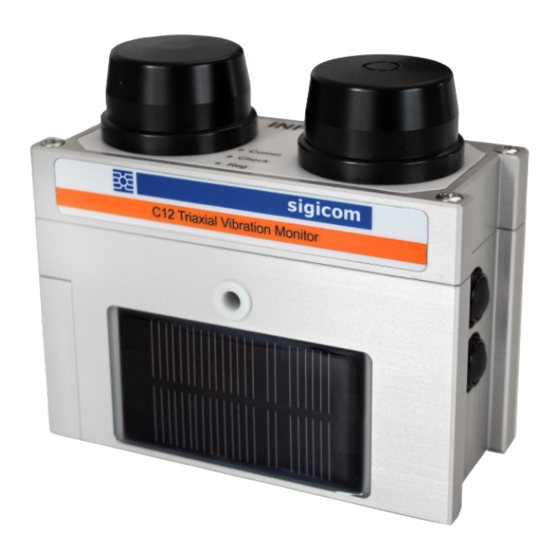
1.2. INFRA C12 Triaxial Vibration Monitor The INFRA C12 is a complete wireless vibration monitor measuring in three directions. It consists of a tri-axial vibration sensor, together with measuring electronics, digital signal processing, CompactFlash, quad band GSM/GPRS modem, antenna and batteries. -
Page 10: Automatic Data Transfer Through Gsm/Internet
Note! 3G version can be identified by the product label and is 2G compatible. It does not communicate faster than the 2G version. 1.4. Unpacking and Parts Identification Your INFRA C12 Triaxial Vibration Monitor has been shipped in protective packaging. Please keep this and use it when transporting your equipment. -
Page 11: The Enclosure
Power OFF (see section 5.5). • B1+B2 long Toggle monitoring mode (see sections 5.2 and 5.3). • B1 long Data server connection (see section 5.4.2). Note! ‘Long’ indicates that the button must be pressed for at least three seconds. Copyright © Sigicom AB 2019... -
Page 12: Leds
If you can’t solve the problem after this, contact Sigicom support. Note! On units equipped with a 3G modem, the RSSI value is more unreliable. RSSI values lower than the 20-30% mentioned above may still be enough to send data. Copyright © Sigicom AB 2019... -
Page 13: Check Led (White Or Red)
Reg LED will flash with 50% duty cycle synchronously with the red Check LED. If this happens, it is recommended to check the last .log files on the memory card (if present) to diagnose the problem. Copyright © Sigicom AB 2019... -
Page 14: Antennas
There is one antenna for GSM to the left, and one dummy antenna for future options to the right. If the antenna is removed, the SMA connector can be connected to an external antenna instead (contact Sigicom for more information on this matter). -
Page 15: Solar Panel
There are two power options available through this port: 1. Input for a 5V battery eliminator/charger (Sigicom art. no. 080-01676-0 Power supply). 2. Input for an external 12V battery or solar panel. This input has an under-voltage protection switch at 11.0V. -
Page 16: Usb Connector (Mini-B Type)
It is recommended to use the firmware upgrade module in INFRA Net Manager. • There is also a separate document at the Sigicom support site with instructions how to upgrade the firmware manually. 2.8. CompactFlash The C12 uses a CompactFlash, which is a well-established standard as memory in digital cameras, industrial computers etc. - Page 17 Note! The C12 should not be used without a CompactFlash inserted. If the CompactFlash is missing during startup, all LEDs will first be lit for approx. 60 seconds. After that the Check LED (red) and Reg LED (green) will flash simultaneously until the instrument is turned off. Copyright © Sigicom AB 2019...
-
Page 18: Sim Card
2.9. SIM Card A SIM card must be inserted into the C12 instrument for the GSM communication to work. We suggest the use of Sigicom branded SIM cards. The SIM card must have an active GSM subscription, including GPRS access. -
Page 19: Measuring Parts Of The System
A digital signal processor (DSP) filters, compensates and detects the signals according to the selected measurement standard. Every geophone is regarded as an individual, and an adjustment is made with respect to the characteristics of that specific geophone. This gives measurements of high quality. Copyright © Sigicom AB 2019... -
Page 20: Measuring Logic
The timestamp of the interval is set to the time when it was saved. The interval time can be set to a value between 5 seconds and 20 minutes using INFRA Net. The same value applies to all three nodes. Copyright © Sigicom AB 2019... -
Page 21: Frequency Detection, Weighting And Trigger Filter
Note! The trigger event is delayed until the zero crossing after the signal maximum. • Direct SMS messages or INFRA Server messages sends weighted vibration level values. • The log file still contains the unweighted vibration level, and considers only post-trig data. Copyright © Sigicom AB 2019... -
Page 22: Transient Recording
Analogously, if analog or digital overload occurs in one or more samples during recording of the transient, the corresponding transient file will be tagged with an overload flag. In this way INFRA Net can indicate possible overload in its interval and transient data reports. Copyright © Sigicom AB 2019... -
Page 23: File Types
S2 is the serial number of the individual C12 node (xxxx0, xxxx1or xxxx2). • C is the channel of the measurement standard. Example 1: ‘INFRA_60300_0_101_0dedff51.log’ Example 2: ‘C12T_60302_1_12_0733b551.interval’ Note! Interval and transient files are node specific. Log files are common for the C12 instrument. Copyright © Sigicom AB 2019... -
Page 24: Event Files (.Log)
Node identity (e.g. C12V). • Calibration data. • Measurement standard. • Data quantity (e.g. velocity). • Data unit (e.g. mm/s). • Presentation control (resolution, no. of significant digits). • Monitoring start/stop flags. • Overload flags. Copyright © Sigicom AB 2019... -
Page 25: Transient Files (.Transient)
The post processing Web application (INFRA Net) includes all the measurement standard algorithms that the C12 uses. (It can also include ‘virtual’ standards, which don’t exist in the C12, or standards under development.) Copyright © Sigicom AB 2019... -
Page 26: Data Storage On Compactflash
Otherwise the memory card will eventually become full. Check the directories creation date to decide which directories to delete. If unsure, check in the post-processing system (e.g. INFRA Net) for missing data before deleting any files on the memory card. Copyright © Sigicom AB 2019... -
Page 27: Configuration And Installation
‘at+cgdcont=1,"IP","online.telia.se";d*99**PPP*1# ‘ ‘pppuser.txt’ and ‘ppppasswd.txt’ may be needed for the GPRS connection. If so, this information should be provided by the GSM operator. Note! No changes of the GSM settings are needed for the 3G version. Copyright © Sigicom AB 2019... -
Page 28: Running Without Data Transfer
It can be used to identify e.g. a point of measurement in a project, and may be 4 characters long at maximum. • It can be changed in INFRA Net. • Note! Node ID text is also used in the setup of weighted standards, see 3.2.3. Copyright © Sigicom AB 2019... -
Page 29: Sms Settings
After the phone number, a note of the receivers name can be entered. Examples: /+4670135565335 # John (off) S+46479003030303 # Peter (service) A+467021343556 # Mary (all) +4670545262626#Henry (data) Note! The SMS function does not work if the GSM function is turned OFF. Copyright © Sigicom AB 2019... -
Page 30: Infra Net Messages
10 seconds when using standards without frequency channels. • 20 seconds when using standards with frequency channels. Otherwise some Live data can be missing. Recorded interval data, sent to the ordinary data server are not affected by this restriction. Copyright © Sigicom AB 2019... -
Page 31: Factory Default Settings
LEDs pointing up (see front page). For correct measuring results, the mounting angle of the C12 instrument must not exceed 5º relative to the horizontal plane. Refer to Sigicom product catalog for more information on mounting solutions. Note! C12 must not be submerged in water. -
Page 32: Operation
(green) will flash fast to indicate the mode transition. After a few seconds (depending on selected standard), the Reg LED changes to slow flashing (once per two seconds). The instrument is now in monitoring mode. Copyright © Sigicom AB 2019... -
Page 33: Sensor Test
The test pulses are recorded and saved in each transient file and can be viewed in the Triax/ Multi Reports in INFRA Net. The analyzed result of the sensor test is also uploaded to be presented in the Remote module of INFRA Net. Copyright © Sigicom AB 2019... -
Page 34: Stop Monitoring
5.4.1. Automatic Data Server Connection An automatic data server connection will be done at the following situations: • After start or stop of monitoring. • After a transient recording. • When an error has been detected. • When scheduled. Copyright © Sigicom AB 2019... -
Page 35: Manual Data Server Connection
– on procedure caused by a remote parameter change. Any such activity must be allowed to finish before power off can be performed. Note! Power off may also be inhibited by external charging (see section 2.6). Copyright © Sigicom AB 2019... -
Page 36: Power Lost
(e.g. the threshold level), will cause the instrument to enter monitoring off mode, then change the parameters, and restart monitoring again. Other parameters (e.g. the data server connection schedule), can be changed without a monitoring stop/restart procedure. Copyright © Sigicom AB 2019... - Page 37 ‘IMnnnnn.control’, where ‘nnnnn’ is the serial number of the C12. Note! It is possible to remotely change the ‘communication’ parameters stored in the ‘config’ directory of the CompactFlash. In this case Sigicom support should be contacted. Note! The ‘remote’ directory must exist on the data server before the INFRA Remote system can be used.
-
Page 38: Other Functions
NTP server. If needed, the ‘ntpserver.txt’ file can be changed through INFRA Net. Sigicom is supplying an NTP service at ‘ntp.infra.sigicom.net’, which can be written in the ‘ntpserver.txt’ file. In monitoring off mode, time synchronization is performed after every manual data server connection. -
Page 39: Daylight Saving Time
INFRA Net. Note! New C12 may have factory settings of the clock and time zone, which not fully matches your local standards. Use INFRA Net to alter these settings. Copyright © Sigicom AB 2019... -
Page 40: Skip File Archive
CompactFlash will not become full. The first row in the file must be ‘1’ to disable the archive system. Note! To skip file archiving is the default on delivery. Copyright © Sigicom AB 2019... -
Page 41: Technical Specifications
• 850/1900 MHz, for users in the US. Reference Standard: conditions: Vibration level: 10 mm/s Frequency: 80 Hz Ambient temperature: 23 ºC Static pressure: 101.3 kPa Accuracy: Follows all requirements in the various measurement standards. Copyright © Sigicom AB 2019... -
Page 42: Accessories
SMA connector (50-ohm adapters may be used) • Gain: not better than 3 dBi • VSWR: better than 3:1 within the used frequency ranges See latest INFRA product catalogue for a complete list of accessories and more details. Copyright © Sigicom AB 2019... -
Page 43: Maintenance And Calibration
• If sent to repair, please carefully write down the description of the problem. It is also recommended contacting Sigicom before sending the unit for repair. Copyright © Sigicom AB 2019... -
Page 44: Contact And Support
+46 8 44 99 750 USA: Sigicom Inc. 2636 Midpoint Drive Ste B Fort Collins, Colorado 80525 United States +1 (970) 493-1552 Web: http://www.sigicom.com Support: Phone: +46 8 44 99 770 Email: support@sigicom.com Web: http://support.sigicom.com/infra Copyright © Sigicom AB 2019... -
Page 45: Battery Voltage Limits
The State of charge parameter is used for presentation in INFRA Net etc. If battery is recovering from a previous level below ’BAT LOW set’, the Check LED blink will remain red until ’BAT LOW clear’ is reached again. State of charge will remain at 25%. Copyright © Sigicom AB 2019... -
Page 46: Configuration File Reference List
Skip file archive ‘noarchive.txt’ Log of the last failed GSM ‘modemlog.txt’ connection Agenda script ‘agenda.txt’ Server messages receivers ‘smsdest.txt’ Server messages server ‘eventauth.txt’ Server messages authentication ‘eventserver.txt’ INFRA Net Live server ‘onlineauth.txt’ INFRA Net Live ‘onlineserver.txt’ authentication Copyright © Sigicom AB 2019... -
Page 47: Li-Ion Battery Transport
Transport by Air is prohibited according to the IATA Special Provision A154. • Follow safety instruction for Li-Ion batteries in the beginning of this manual. • Call Sigicom for consultation before any transportation. Note! Worn out batteries are forbidden in air transport. Copyright © Sigicom AB 2019... -
Page 48: Safe Handling Of Li-Ion Batteries
• Place the safety instruction easily seen in all sites where batteries are handled. • Inform personnel about the instruction. • Report all safety related events to management. Reference: http://batteryuniversity.com/learn/article/safety_concerns_with_li_ion Copyright © Sigicom AB 2019... -
Page 49: In Case Of Li-Ion Battery Fire
COMBUSTABLE MATERIAL PLACE THE BATTERY IN SAND FILLED BUCKET, PLACE OUTSIDE IF POSSIBLE USE FIRE EXTINGUISHER WATER IS OK IF NO OTHER KIND OF FIRE EXTINGUISHER IS AVAILABLE PUT SEEMINGLY BURNED-OUT BATTERY OUTSIDE FOR A TIME Copyright © Sigicom AB 2019... -
Page 50: Operator's Registration Template
• The disposal rules of the batteries used in the equipment. Date: Name: Organization: Phone no: Sign: Scan and send copy by E-mail or send original by air-mail to Sigicom. See chapter 10 Contact and Support. Copyright © Sigicom AB 2019... -
Page 51: Measurement Standards
5. “Trigger filter” A variant of the “discrete frequency type”, where only the trigger algorithm for recordings uses the weighted data. Copyright © Sigicom AB 2019... - Page 52 9012 mm/s RMS 1s ISO 8569 125 m/s 5 – 300 Hz Accel ISO 10816-2 5 – 500 Hz RMS 1 s mm/s DIN 4150-3 Discrete 1 – 315 Hz frequency Anlage mm/s type Copyright © Sigicom AB 2019...
- Page 53 ISO2631-2 type RMS 1s BS 7385 25 mm/s 1 – 300 Hz AS 2187.2-2006 2 – 250 Hz mm/s Particle displac 1500 10 – 60 Hz µm Particle displac 250 µm 1 – 300 Hz Copyright © Sigicom AB 2019...
- Page 54 2 – 250 Hz filter Seismograph ISEE 1 in/s 2 – 250 Hz Trigger filter Seismograph Geophone 5 – 500 Hz mm/s ISEE/USBM 2 – 250 Hz mm/s ISEE/USBM 25 mm/s 2 – 250 Hz Copyright © Sigicom AB 2019...
- Page 55 Level, frequency ranges: 25 mm/s, 2-150 Hz Max resolution in presentation: 0.005 mm/s and 3 significant digits. Threshold range 0.04 – 22 mm/s. Transient file resolution: ~0.001 mm/s. Copyright © Sigicom AB 2019...
- Page 56 20 mm/s, RMS, 1-80 Hz Filtered according to ISO 2631-2, time constant 125 ms. Max resolution in presentation: 0.005 mm/s RMS and 3 significant digits. Threshold range 0.04 – 15 mm/s. Transient file resolution: ~0.001 mm/s. Copyright © Sigicom AB 2019...
- Page 57 Erschütterungen im Bauwesen – Teil 3: Einwirkungen auf bauliche Anlage. Level, frequency ranges: 25 mm/s, 1-80 Hz Max resolution in presentation: 0.005 mm/s and 3 significant digits. Threshold range 0.04 – 20 mm/s. Transient file resolution: ~0.001 mm/s. Copyright © Sigicom AB 2019...
- Page 58 3000 r/min and 3600 r/min. Level, frequency ranges: 200 mm/s, RMS 1s, 5-500 Hz Max resolution in presentation: 0.05 mm/s RMS, and 3 significant digits. Threshold range 0.2 – 180 mm/s. Transient file resolution: ~0.01 mm/s. Copyright © Sigicom AB 2019...
- Page 59 20 mm/s RMS, 1-80 Hz Filtered according to ISO 2631-2, time constant 1 s. Max resolution in presentation: 0.005 mm/s RMS and 3 significant digits. Threshold range 0.04 – 15 mm/s. Transient file resolution: ~0.001 mm/s. Copyright © Sigicom AB 2019...
- Page 60 Level, frequency ranges: 25 mm/s, 3-400 Hz Max resolution in presentation: 0.005 mm/s and 3 significant digits. Threshold range 0.04 – 22 mm/s. Transient file resolution: ~0.001 mm/s. Copyright © Sigicom AB 2019...
- Page 61 Replaced by #51 in rev: 1.5.0 ISEE Performance Specifications For Blasting Seismographs. Level, frequency ranges: 10 in/s, 2-250 Hz Max resolution in presentation: 0.002 in/s and 3 significant digits. Threshold range 0.02 – 9 in/s. Transient file resolution: ~0.0004 in/s. Copyright © Sigicom AB 2019...
- Page 62 Threshold range 10-1300 µm. Transient file resolution: ~0.2 µm. Note! The stated range/resolution in “displacement” is only valid at 16Hz and below because sensor element measures velocity. At higher frequencies the range/resolution is scaled down. Copyright © Sigicom AB 2019...
- Page 63 Level, frequency ranges: 250 mm/s, 1-150 Hz Max resolution in presentation: 0.05 mm/s and 3 significant digits. Threshold range 0.4 – 220 mm/s. Transient file resolution: ~0.01 mm/s. Copyright © Sigicom AB 2019...
- Page 64 Based on the ISEE standard, but in SI units. Level, frequency ranges: 250 mm/s, 2-250 Hz Max resolution in presentation: 0.05 mm/s and 3 significant digits. Threshold range 0.4 – 220 mm/s. Transient file resolution: ~0.01 mm/s. Copyright © Sigicom AB 2019...
- Page 65 Based on the ISEE standard, but in SI units. Level, frequency ranges: 25 mm/s, 2-250 Hz Max resolution in presentation: 0.005 mm/s and 3 significant digits. Threshold range 0.04 – 22 mm/s. Transient file resolution: ~0.001 mm/s. Copyright © Sigicom AB 2019...
-
Page 66: Tables Of Weighted Standards
<30 Hz 3 mm/s **X3 nent Stan- Standard Variant Reference Reference Customer dard name frequency level string Arrêté du 5 - 30 Hz 10 mm/s **** 1994 Note! For standard 40, weighting is always active. Copyright © Sigicom AB 2019... - Page 67 <8 Hz 2 mm/s **C3 Circ86 très sensible ICPE- Impulsion <8 Hz 8 mm/s **I1 Circ86 résistant ICPE- Impulsion <8 Hz 6 mm/s **I2 Circ86 sensible ICPE- Impulsion <8 Hz 4 mm/s **I3 Circ86 très sensible Copyright © Sigicom AB 2019...
- Page 68 2 mm/s **C3 continu très sensible S42, IN1226 Vibration <10 Hz 5 mm/s **C4 continu Plateforme S42, IN1226 Vibration <10 Hz 8 mm/s **I1 transitoire résistant S42, IN1226 Vibration <10 Hz 6 mm/s **I2 transitoire sensible Copyright © Sigicom AB 2019...
- Page 69 S42, IN1226 Vibration <10 Hz 4 mm/s **I3 transitoire très sensible S42, IN1226 Vibration <10 Hz 8 mm/s **I4 transitoire Plateforme Copyright © Sigicom AB 2019...
- Page 70 Trigger filter only, no weighted data values: Stan- Standard Variant Reference Reference Customer dard name frequency level string S51, ISEE Plaster 3 – 10 Hz 0.5 inch/s **UP S51, ISEE Drywall 4 – 15 Hz 0.75 inch/s **UD Copyright © Sigicom AB 2019...
-
Page 71: The Use Of Weighting Standard
In this example we study Zeile 1 (Line 1), which for example allows • 2.0 times higher velocities at 50 Hz compared to frequencies < 10 Hz • 2.5 times higher velocities at 100 Hz compared to frequencies < 10 Hz Copyright © Sigicom AB 2019... - Page 72 The limits in figure I1 lead to the weighting curves in figures I2 – I4, which are implemented in the firmware of INFRA C12. Figure I2. The weighting of the measured signal, made by the C12 firmware when configured with standard DIN 4150-3, Zeile 1.
- Page 73 Figure I3. The weighting of the measured signal, made by the C12 firmware when configured with standard DIN 4150-3, Zeile 2. Copyright © Sigicom AB 2019...
- Page 74 Figure I4. The weighting of the measured signal, made by the C12 firmware when configured with standard DIN 4150-3, Zeile 3. Copyright © Sigicom AB 2019...
-
Page 75: The Use Of Us Standard Isee Seismograph (S51 And S52)75
(2.65 – 10 Hz) Figure J1. Trigger filter for S51 ISEE Seismograph. The nominal level is defined in the frequency interval 4 – 15 Hz for Drywall, and in the frequency interval 2.6 – 10 Hz for Plaster. Copyright © Sigicom AB 2019... - Page 76 0.25 in/s, if its frequency is in the range 4 - 15 Hz • 0.67 in/s, if its frequency is larger than 40 Hz As can be seen, all three figures above are decreased to a third of the %.'( )*/, values in Example 1. [ " %.-( )*/, Copyright © Sigicom AB 2019...
- Page 77 1.0 in/s, if its frequency is in the range 2.6 - 10 Hz • 4.0 in/s, if its frequency is larger than 40 Hz As can be seen, all three figures above are doubled compared to the !.% )*/, values in Example 3. [2 = %.(% )*/, Copyright © Sigicom AB 2019...
Need help?
Do you have a question about the INFRA C12 and is the answer not in the manual?
Questions and answers