Table of Contents
Advertisement
Quick Links
Advertisement
Table of Contents

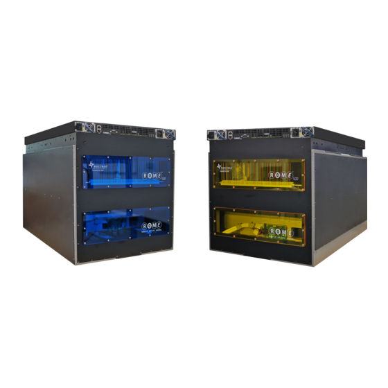
Summary of Contents for Wave2wave Fiber Smart Networks ROME 500
- Page 1 Hardware Installation Manual DOC-0002...
- Page 2 Hardware Installation Manual ROME and LCU are registered trademarks of Wave2Wave and/or its affiliates in the U.S.A. and certain other countries. All other brands, names and trademarks mentioned in this document are the property of their respective owners. The use of the word “partner” does not imply a partnership relationship between Wave2Wave and any other company.
-
Page 3: Table Of Contents
Hardware Installation Manual TABLE OF CONTENTS Introduction 1.1 About This Document 1.2 Audience 1.3 Safety Warnings Pre-Installation 2.1 Parts List 2.2 Rack Planning 2.2 Installing Slider Mounting Units Preparing ROME 3.1 Installation Preparation 3.2 Unpacking ROME Installing the ROME Chassis 4.1 Mounting the ROME Chassis 4.2 Mounting the Patch Panel 4.3 Cabling (Fiber and Ground) -
Page 4: Introduction
Introduction About This Document This guide provides step by step instructions for the installation of the Wave2Wave Robotic Optical Management Engine (ROME) system, as well as important information on Standards, Agency193 Approvals, and Safety warnings. Please read all the safety warnings before beginning installation. - Page 5 Hardware Installation Manual Electrical Current Possible Laser Hazard Electrical current from power, telephone, and This device can switch laser based source signals, which, communication cables is hazardous. at higher wattage levels, require additional precautions 1. Do not connect or disconnect any power cables or by the user.
-
Page 6: Pre-Installation
Hardware Installation Manual Pre-Installation Once the ROME unit and the hardware is ready to be installed into rack. Remove the ROME slider rails from the kit and adjust the slider rails to a minimum of 29" which is the required depth needed for proper installation of ROME chassis, to a maximum of 46 inches. -
Page 7: Rack Planning
Hardware Installation Manual Rack Planning When planning rack configuration, remember to allocate 1RU space in the rack for the LCU. The LCU may be installed in any location within the rack, including directly above the ROME. If installing ROME in a populated rack, install ROME in the lowest available space on the rack. The ROME Chassis uses non-forced air cooling. - Page 8 Hardware Installation Manual 3. Secure the back side of the slider rail unit to the back post, use a level to make sure the slider rail unit is level. 4. Tighten the slider brackets screws to the slider body and stiffener. 5.
-
Page 9: Preparing Rome
Hardware Installation Manual Preparing ROME Installation Preparation Before beginning the installation of ROME equipment, please make sure to: • Wear an ESD strap. • Have a mechanical lifting device available, such as the one pictured, which is required to lift and maneuver the heavy, 87 kg (191.8lbs) ROME equipment, to avoid possible bodily injury. -
Page 10: Unpacking Rome
4. After the box is unpacked, inspect the internal shock watch indicator and all elements of the unit for damage. If either the indicator is activated or if there is any damage to the ROME equipment, please do not proceed with installation and contact Wave2Wave. Page 10... -
Page 11: Installing The Rome Chassis
Hardware Installation Manual Installing the ROME Chassis Installing the ROME Chassis involves the following steps: Mounting the ROME Chassis Mounting the patch panel Cabling (fiber and ground) Note: Configuring the ROME equipment is covered in the ROME Administrator Manual. Option 1: You will need a total of 20 RUs to properly install ROME chassis, LCU and fiber patch panel in front of rack. -
Page 12: Mounting The Patch Panel
Hardware Installation Manual 8. Once the chassis is securely attached to the slider bracket system, the lift can be removed. 9. It is optional to remove the protective bottom plate that has been protecting the underside of ROME during the installation process. Please be sure to store plate for future relocation. The plate can be removed by unscrewing the 4 bolts at each corner of plate (Allen #6). -
Page 13: Cabling (Fiber And Ground)
Hardware Installation Manual Cabling (Fiber and Ground) 4.3.1 Organizing the Fiber Cable The slack fiber cable from the ROME Chassis should be spooled and secured to the rear of the patch panel. Sufficient slack should be allowed to fully extend the ROME Chassis outwards for maintenance. 4.3.2 Grounding the ROME Chassis Connect the customer facility ground to the ROME Chassis at the attachment point which is located at the lower left corner when looking at the back of the ROME (refer to the pictures below). -
Page 14: Installing The Lcu
Hardware Installation Manual Installing the LCU Each ROME Chassis is controlled by an LCU. The LCU install kit includes the LCU, a signaling cable (Y-Cable) to attach to the ROME Chassis, and a ground cable. 1 RU of space above the LCU is recommended to allow adequate space for connecting the LCU control and ground cable. - Page 15 Hardware Installation Manual 2. Connect the cable to the back of the corresponding ROME Chassis The signaling cable from the LCU to the ROME Chassis should be tied down to the rack to organize the cable. When it is tied down properly, the cable should have enough slack to allow ROME Chassis to slide out for maintenence.
-
Page 16: Powering Up Rome
Hardware Installation Manual Powering Up ROME Once the ROME Chassis and LCU have been installed, connected through signaling Y cable, and properly grounded, the ROME equipment can be powered up. The power cable connections are located on the front panel of the LCU. Use provided 2 power cables (15P to C15, SJT 14AWG) and plug in to turn on the ROME. -
Page 17: Appendices
Hardware Installation Manual Appendix 1 - ROME Dimensions 17.42in (442.50mm) 16.83in (427.50mm) ROME - Front View Dimensional Details UNLESS OTHERWISE SPECIFIED: DIMENSIONS ARE IN MILLIMETERS SURFACE FINISH: TOLERANCES: LINEAR: ANGULAR: NAME SIGNATURE DATE YONATAN DRAWN CHK'D APPV'D 0.63in (16mm) 0.2in (5mm) 30.32in (770mm) 31.14in (791mm) ROME - Side View Dimensional Details (mm) -
Page 18: Lcu Dimensions
Hardware Installation Manual Appendix 2 -LCU Dimensions 16.93in (430mm) 16.93in (430mm) 17.48in (444 in) 16.93in (430mm) Front View 17.48in (444 in) 16.93in (430mm) 29.39in (745.5mm) 1.73in (44mm) 28.16in ( 715.2mm) Side View 29.39in (745.5mm) 1.73in (44mm) 28.16in ( 715.2mm) 27.49in (698.2mm) 27.49in (698.2mm) Top View 17.44in (443mm) -
Page 19: Patch Panel Dimensions
Hardware Installation Manual Appendix 3 - Patch Panel Dimensions 6.05in (153.6mm) 18.98in (482mm) 4.98in (126.6mm) Appendix 4 - Console Cable Pinout Signals and Pinouts for the Console RJ-45 to DB-9 Serial Cable Console Cable Pinout Console Port PC COM Port RJ-45 DB-9 Pins... -
Page 20: Rome Specifications
Hardware Installation Manual Appendix 5 - ROME Specifications Specifications ROME® 500 ROME® 64Q ROME® 128Q Optical Characteristics Fiber 512 Fibers 512 Fibers 1,024 Fibers • Duplex Tandem Any to Any 8 Fiber Any to Any 8 Fiber Any to Any •... - Page 21 Hardware Installation Manual Standards Compliance Safety Compliance · ANSI/UL 60950-1 / CSA 60950-1 (USA / Canada) · EN60950-1 (Europe) · IEC60950-1 (International), CB Certificate & Report Including All Group and Country Deviations · Low Voltage Directive 2006/95/CE (Europe) EMC Compliance ·...
- Page 22 1RU (1.71in) Innovate • Design • Manufacture Contact U.S. Headquarters 47775 Fremont Blvd • Fremont, CA 94538 phone: +1 408-586-8800...
Need help?
Do you have a question about the Fiber Smart Networks ROME 500 and is the answer not in the manual?
Questions and answers