Table of Contents
Advertisement
Quick Links
Advertisement
Chapters
Table of Contents

Related Manuals for NETZSCH LFA 447 Nanoflash

Summary of Contents for NETZSCH LFA 447 Nanoflash
- Page 1 LFA 447 Operating Instructions Operating Instructions LFA 447 Nanoflash Contents General Information Chapter I Chapter II Installation Chapter III System Components Operating the Instrument Chapter IV Chapter V Appendix 01/09 J:\LFA447\Contents.doc...
- Page 2 Chapter I LFA 447 General Information 01/09 J:\LFA447\CHAPTER1.DOC...
- Page 3 E-Mail: at@netzsch.com Internet: http://www.netzsch-thermal-analysis.com Maintenance and service must be carried out by NETZSCH Customer Service personnel. A service contract is available for our customers. This instruction manual is provided to give the customer information on proper operation of the instrument. NETZSCH-Gerätebau GmbH will accept no liability for damage resulting from improper use.
- Page 4 LFA 447 General Information Notes on the Use of this Manual In this manual, the symbols described below are used to simplify orientation. NOTE! This sets particularly important information apart from the rest of the text. ATTENTION! These instructions must be followed exactly to avoid injury to the user and damage to the instrument.
- Page 5 Authorized Any operation of the instrument other than as authorized Operation requires consultation with NETZSCH. Any use exceeding the (expanded) authorized operation is considered unauthorized. The manufacturer will not be liable for any damage resulting from such use.
- Page 6 LFA 447 General Information Maintenance The operator of the system must ensure that the instrument is operated in perfect condition at all times. Obligation The operator must guarantee the openness and cleanliness of Proper Set-up of the the work stations at the instrument through appropriate Work Stations instruction and inspections.
- Page 7 LFA 447 General Information Operating Using the Operation Manual, the operator should prepare operating instructions which specify the actions and tasks Instructions required for safe operation. The operating instructions should be placed in a suitable location in the work place and complied with by the employees. Gases Observe the relevant regulations and protective measures when handling the required gases.
- Page 8 LFA 447 General Information Safety regulations for handling liquid nitrogen LN It is imperative that you observe the safety regulations for handling nitrogen. FIRE AND EXPLOSION HAZARDS Neither gaseous nor liquid nitrogen are flammable and do not in themselves constitute a fire or explosion risk. However, both gaseous and liquid nitrogen are normally stored under pressure and the storage vessels, whether gas containers or liquid tanks,...
- Page 9 LFA 447 General Information HEALTH HAZARDS Asphyxia Nitrogen, although non-toxic, can constitute an asphyxiation hazard through the displacement of the oxygen in the atmosphere. The potential for this type of hazard is significant because of the widespread use of nitrogen as a purging or blanketing gas in chemical, metallurgical, and other industrial operations and because neither nitrogen gas nor oxygen depletion are detectable by the normal human senses.
- Page 10 LFA 447 General Information Frostbite Severe or prolonged exposure to cold nitrogen vapor and gas can cause frostbite. Local pain usually gives warning of freezing, but sometimes no pain is experienced. Frozen tissues are pain-free and appear waxy with a pallid yellowish color. Thawing of the frozen tissues can cause intense pain.
- Page 11 LFA 447 General Information PRECAUTIONS Operations and maintenance It is essential that operations involving the use of gaseous or liquid nitrogen, particularly where large quantities are used, are conducted in well-ventilated areas to prevent the formation of oxygen-deficient atmospheres. Ideally, nitrogen should be vented into the open air well away from areas frequented by personnel.
- Page 12 LFA 447 General Information Personnel protection It is recommended that persons handling gas containers wear safety glasses, safety footwear and clean, sturdy gloves. Persons handling equipment in service with liquid nitrogen should wear protective face shields, loose fitting leather or insulated gauntlets.
- Page 13 LFA 447 General Information Treatment by medical practitioner or hospital a) Remove any clothing that may constrict the circulation to the frozen area. Remove patient to sick bay or hospital. b) Immediately place the part of the body exposed to the cryogenic material in a water bath which has a temperature of not less than 40°C (104°F) but not more than 45°C (113°F).
- Page 14 LFA 447 General Information GAS CONTAINERS The content of the container is primarily identified by a label attached to the container shoulder and secondarily by the color of the container. The Air Products identification colors for containers containing nitrogen are: Body: French gray;...
- Page 15 LFA 447 General Information Storage and handling − Where necessary for toxic gases, see that self-contained positive pressure breathing apparatus or a full face air line respirator is available in the vicinity of the working area. − Check for gas leaks using a suitable method. Flammable and toxic gas monitors are available.
- Page 16 LFA 447 General Information − Replace outlet caps or plugs and container caps (where provided) as soon as container is disconnected from equipment. Storage − Containers should be stored in a well-ventilated area. Some gases will require a specially built area. −...
- Page 17 LFA 447 General Information LIQUID STORAGE CONTAINERS − Liquid nitrogen is stored and transported either in purpose built storage tanks or dewar flasks. Storage quantities vary from a few liters for dewar flasks to several thousands of liters for storage tanks. The storage tanks are pressurized, insulated containers which are installed in accordance with established codes of practice.
- Page 18 Chapter II LFA 447 Installation 01/09 J:\LFA447\CHAPTER2.DOC...
-
Page 19: Table Of Contents
LFA 447 Installation Contents .....................1 NSTALLATION ................1 ACKING AND ELIVERY ................2 OCATION EQUIREMENTS .................3 NSTALLATION SCHEMATICS ..............4 ONNECTING THE COMPUTER SYSTEM ................5 ONNECTING THE THERMOSTAT 01/09 J:\LFA447\CHAPTER2.DOC... -
Page 20: Installation
LFA 447 Installation Installation In most cases, your LFA 447 is set up and commissioned by one of our customer service engineers. If you would like to set up your instrument yourself, please read the following sections. Packing and Delivery We deliver all components in separate cartons. -
Page 21: Location Requirements
LFA 447 Installation Location Requirements Select the optimal component arrangement for the space you have available. The location of your instrument must meet the following requirements: constant temperature conditions (room temperature) to the extent possible no direct sunlight on the instruments dust-free environment to the extent possible measuring system A stable, shock-absorbent table with a working surface of... -
Page 22: Installation Schematics
LFA 447 Installation Installation schematic depth 610 depth 450 depth 500 Ln max. 2l/day on line sta te te mp I te mp II LFA 447 measuring part LFA 447 computer printer table 230 V (115 V), 6 A weight: 10.5 Kg weight: 12 Kg monitor weight: 3.5 Kg... -
Page 23: Connecting The Computer System
LFA 447 Installation Connecting the system components Connecting the computer system sensor connection LFA 447 (rear) computer connection (serial port) WATER INLET WATER OUTLET power supply Figure 2: connecting the computer system For connecting the computer system, see also the technical documentation of the computer manufacturer. -
Page 24: Connecting The Thermostat
LFA 447 Installation Connecting the thermostat LFA 447 (rear) water inlet WATER INLET WATER OUTLET water outlet thermostat (rear) water filter outlet inlet ALARM power supply Figure 3: connecting the thermostat Adjust the temperature of the thermostat 2°C - 3°C below room temperature (e.g. - Page 25 Chapter III LFA 447 System Components 01/09 J:\LFA447\CHAPTER3.DOC...
- Page 26 LFA 447 System Components Contents ..................1 EASURING UNIT ..............2 ETAILS OF THE MEASURING UNIT ....................3 RONT PANEL ....................4 ACK PANEL ..................5 XTRACTOR TOOL ..................6 AMPLE HOLDER ..............7 TANDARD SAMPLE HOLDERS ................... 7 ROUND SAMPLES ................... 7 SQUARE SAMPLES ...............8 PECIAL SAMPLE HOLDERS •...
-
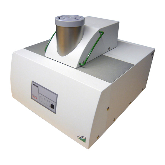
Page 27: Measuring Unit
LFA 447 System Components Measuring unit height depth width ® Figure 1: LFA 447 measuring unit 01/09 J:\LFA447\CHAPTER3.DOC... -
Page 28: Details Of The Measuring Unit
Figure 2: details of the measuring unit The LFA 447 Nanoflash is equipped with a furnace capable of operation from room temperature to 300°C. The system is equipped with a software-controlled automatic sample changer allowing measurement of up to 4 samples at the same time. The temperature rise on the back face of the sample is measured using an In-Sb detector. -
Page 29: Front Panel
LFA 447 System Components Front panel detector housing hood ® operating elements online status charged interlock LFA 447 Figure 3: front panel of the measuring unit label function online green LED lights up: instrument is switched on status start the software - click on the Nanoflash™ icon: the status light on the front panel lights up in a red, yellow, green sequence once communication is established charged... -
Page 30: Back Panel
LFA 447 System Components Back panel WATER INLET WATER OUTLET Figure 4: back panel of the measuring unit label function 6A, 240 V mains fuses power switch power switch: instrument “on/off” AC input power connection 230 (115) V detector amplifier signal connection to the detector thermostat outlet connection: cooling water outlet... -
Page 31: Extractor Tool
LFA 447 System Components Extractor tool handhold knob clip Figure 5: extractor tool The extractor tool is used to open the individual components of the sample holder. Operating principle Fix the lower end of the extractor tool in the respective part of the sample holder (e.g. furnace lid, the two fixing bolts on the lower part of the extractor tool must be clamped into the holes of the furnace lid). -
Page 32: Sample Holder
LFA 447 System Components Sample holder Individual parts extractor tool furnace lid mask sample (round or square) sample holder plate (round or square inserts) sample tray furnace Figure 7: individual parts of the sample holder The vertical installation of the flash lamp and the IR detector allows a very easy sample holder handling. -
Page 33: Standard Sample Holders
LFA 447 System Components Standard sample holders The samples must be placed into the sample holder plate and covered by the corresponding mask. round samples square samples sample holder plate with mask sample holder plate with mask - size 1 - - size 1 - sample holder plate mask... -
Page 34: Special Sample Holders
LFA 447 System Components operating principle: mask sample (round or square) sample holder plate (round or square inserts) Figure 8: operating principle standard sample holder Special sample holders • Sample holder for laminated samples The sample must be cut into single sample strips (A) (strips length: 12.7 mm), placed into the sample holder plate (B), affixed by the two fixing screws (C) and covered by the corresponding mask (D) (see Figure 9). - Page 35 LFA 447 System Components In addition: The sample holder for laminated samples can also be used for in-plane measurements (anisotropic samples). In order to achieve this, the sample must also be cut into single sample strips (E) (strips length: 12.7 mm) which must be turned by 90° (on their side) (F) so that the sample can be measured in a horizontal direction.
-
Page 36: • In-Plane Sample Holder
LFA 447 System Components • In-plane sample holder (for measurements of a round sample in a horizontal direction) The In-plane sample holder is designed so that the position for the energy input on the bottom side of the sample and the position for measuring the temperature increase on the top side of the sample (energy output) are located at different lateral positions. -
Page 37: Sample Holder For Liquids
LFA 447 System Components • Sample holder for liquids By using a special sample holder it is possible to analyze liquids with the LFA 447 instrument. When using the sample holder please pay attention to the following indications. ring of stainless steel crucible liquid sample Figure 12: sample holder for liquids... - Page 38 LFA 447 System Components Determination of the liquid level in the crucible total crucible sample For measurements, the 3 layer model for determination of the thermal diffusivity of the liquid must be used. This means that the bottom thickness of the crucible h crucible the liquid level h and the thickness of the cover bottom h...
- Page 39 LFA 447 System Components Pour the liquid in the crucible • Insert the sample holder plate ∅ 12.7 mm into the sample tray such that the shallow margin (1.6 mm) faces upwards (see figure). sample holder plate Ø 12.7 mm sample tray shallow margin (1.6 mm) (must show to the top)
- Page 40 LFA 447 System Components • pipette Insert a drop of the liquid into the crucible. The volume of the drop should be 50 -60 µl. By known density of the liquid sample it is possible to determine the volume via measurement of the sample mass.
- Page 41 LFA 447 System Components • extractor tool Put the furnace lid in the place. furnace lid A test measurement with water should yield the following result: a = 0.146 mm /s (at room temperature) Example of a measurement: Liquid sample holder 304 V / Long / 3500ms* Signal Ratio (empty/water) <...
- Page 42 LFA 447 System Components The figure (example for water) shows that the calculation range is reduced to 2000 ms. This is strongly recommended for all measurements with the sample holder for liquids due to the heat spreading in the container which influences the detector signal above 2000 ms.
-
Page 43: Sample Holder For Powdery And Pasty Samples
LFA 447 System Components • Sample holder for powdery and pasty samples By using a special sample holder it is possible to analyze powdery and pasty samples with the LFA 447 instrument. When using the sample holder please pay attention to the following indications. - Page 44 LFA 447 System Components • graphite spary Turn the lid and place a cover plate (Ø approx. 10 mm) in the center of the bottom side. Coat the bottom side with graphite spray so that only the edge of the lid (bottom side) is coated.
- Page 45 LFA 447 System Components • Fill the powdery sample into the sample pan. ATTENTION! The powdery sample should exceed slightly from the upper edge of the pan. powder sample powder sample (non-transparent) • Place the lid onto the pan. • Place the upper support plate as shown in the figure and fix it by means of the phillips screws.
- Page 46 LFA 447 System Components Sample preparation for transparent samples: • graphite spary Coat the base area inside of the pan with graphite spray. NOTE! The complete area of the pan must always be coated with graphite spray in order to make sure that the energy will be absorbed on the inner side of the pan.
- Page 47 LFA 447 System Components • Wait some minutes until the coating is dried. coated pan coated lid (inside) (bottom side) • Insert the coated pan into the lower support plate. ATTENTION! The powdery sample should exceed slightly from the upper edge of the pan.
- Page 48 LFA 447 System Components • Place the upper support plate as shown in the figure and fix it by means of the phillips screws. • Check the thickness: The inner distance between pan and lid is approx. 1.5 mm. If the sample is not compressible, a higher sample thickness could result.
-
Page 49: Matrix Sample Holder
LFA 447 System Components • Matrix sample holder The installation and operation are described in chapter 5 “Appendix”! Thermostat A thermostat is required to operate the instrument. This handles thermostatic control of instrument components relevant to the measurement and cooling of the furnace system. The thermostat is connected to the thermostat (inlet-outlet) connections on the back panel of the measuring unit. - Page 50 Chapter IV LFA 447 Operating the Instrument 01/09 J:\LFA447\CHAPTER4.doc...
- Page 51 LFA 447 Operating the Instrument Contents ................1 PERATING THE INSTRUMENT ...................... 1 RINCIPLE ................3 REPARING THE DETECTOR ............... 4 PEN AND CLOSE THE MEASURING UNIT ..................5 AMPLE REPARATION ....................5 AMPLE HICKNESS ....................6 AMPLE OATING ..................6 RANSPARENT ATERIAL .....................
-
Page 52: Operating The Instrument
LFA 447 Operating the Instrument Operating the instrument Principle signal amplifier IR-detector software sample furnace P.C. power filter wheel printer xenon flash tube pulse forming network Figure 1: measuring principle LFA 447 The Nanoflash instrumentation can be used to measure the thermal diffusivity, specific heat and thermal conductivity of metals, graphite, coatings, composites, ceramics, polymers and other materials. - Page 53 LFA 447 Operating the Instrument A mathematical analysis of the measured temperature/time function allows the determination of the thermal diffusivity a. This is carried out in the analysis software which includes different mathematical models for the respective application. The most simple model which is described here for understanding is the “adiabatic model”.
-
Page 54: Preparing The Ir Detector
LFA 447 Operating the Instrument Preparing the IR detector Remove the detector cover from the sensor cover top of the detector casing. Remove the plug from the top of the plug detector casing. Insert the funnel into the free opening. funnel 01/09 J:\LFA447\CHAPTER4.doc... -
Page 55: Open And Close The Measuring Unit
LFA 447 Operating the Instrument Fill in approx. 200 ml liquid nitrogen LN2 storage vessel Wear safety glasses! After a few minutes the detector should be completely filled. The detector cooling stabilizes after 5 minutes. Open and close the measuring unit •... -
Page 56: Sample Preparation
LFA 447 Operating the Instrument Sample Preparation Sample Thickness It is important to use a sample with flat and parallel faces in order to record an accurate value for the sample thickness. To determine the sample thickness: 1. Use a micrometer to measure the sample thickness to at least three significant figures. -
Page 57: Sample Coating
LFA 447 Operating the Instrument Sample Coating Transparent Material The analysis of the flash diffusivity data requires that the energy be absorbed in the surface of the sample. It also requires that only the sample surface temperature is measured by the IR detector. -
Page 58: Sample Mass
LFA 447 Operating the Instrument to coat the samples: 1. Clean all samples with a suitable solvent (including the reference sample if it has been graphite coated previously) and lay them side by side (maintaining sample identification). 2. Shake the can and hold it approximately 10-12 inches from the samples. 3. -
Page 59: Calibration Materials
LFA 447 Operating the Instrument Calibration materials reference samples recommended max. coating temp. [°C] SRM8421 (electrolytic iron) 700°C sandblasting, no graphite above 400°C SRM1461 (steel) 900°C sandblasting, no graphite above 400°C SRM781 (molybdenum) 2000°C sandblasting, no graphite PocoAXM (graphite) 2000°C graphite Pyroceram (ceramics) 900°C... -
Page 60: Insert A Sample
LFA 447 Operating the Instrument Insert a sample • Use the software to move the sample stage to the center position. This is done by clicking “change sample” button main window. Open the LFA 447 measuring unit. Therefore press the interlock button and move the hood to the rear end position (see Figure 4). - Page 61 LFA 447 Operating the Instrument • Place the sample holder plates (round or square) into the sample tray and insert the samples (round or square, as shown in Figure 6 and Figure 7) with corresponding mask. The sample tray can also be moved (removed or installed) by means of the extractor tool. sample holder plates (round or square inserts) sample tray...
- Page 62 LFA 447 Operating the Instrument The Nanoflash sample tray has four positions. Figure 8 shows the sample tray with each individual sample position numbered 1 through 4. sample 1 sample 2 sample 3 sample 4 Figure 8: sample positions • Reinstall the cover by means of the extractor tool and close the measuring unit.
-
Page 63: Staring A Measurement
LFA 447 Operating the Instrument Staring a measurement 1. After software installation, please insert the sample(s) and check the hardware settings: >File>Instrument Configuration 01/09 J:\LFA447\CHAPTER4.doc... - Page 64 LFA 447 Operating the Instrument 2. Check measurement parameters >Measurement>Parameters Please use for first measurements 270V, medium and always 300 points for baseline • A reason to increase the flash lamp power (>270 V, long pulse) is a bad signal-to-noise ratio (maybe 8V signal increase and 4V noise) •...
- Page 65 LFA 447 Operating the Instrument 3. Define samples press corresponding windows or >Samples>Define Sample>1…4 - Choose sample holder, sample name, ID - possible types of measurement: • Single Layer: standard, please enter material, thickness and properties (properties can be changed later after the measurement) •...
- Page 66 LFA 447 Operating the Instrument 4. Press button “Add shots” (green “+” symbol) Select a sample (1 to 4); enter the temperature of the first shot; enter the number of steps if you want to measure at different temperatures; enter the temperature between two steps (Inc.);...
- Page 67 LFA 447 Operating the Instrument 5. Prior to starting a measurement, it is necessary to change the gain and duration for each sample at each temperature manually (up to software version 0.96c); please consider that the maximum increase should be between 2 and 8 Volts – check this after the first shot, maybe the following gain values can be used: 25 C ->...
- Page 68 LFA 447 Operating the Instrument Duration time is too short! Duration time is ok (maximum at 2/5 of total x-range)! 01/09 J:\LFA447\CHAPTER4.doc...
- Page 69 LFA 447 Operating the Instrument 6. Steps to import an LFA measurement file into analysis - Create a new database: >Database>Create new empty - furthermore: >Database>Explore> ---new window is opened--- >Database>Import LFA 447 File ---please select correct directory--- c:\ngbwin\ta\nanoflash\files Double click on the newest file (check the date of files) After this, you have to confirm the following questions with "yes";...
- Page 70 LFA 447 Operating the Instrument 01/09 J:\LFA447\CHAPTER4.doc...
-
Page 71: Procedure For Cp-Determination
LFA 447 Operating the Instrument Procedure for cp-determination The determination of the specific heat using LFA 447 occurs via the comparison method. Exactly the same test conditions for sample and reference are absolutely necessary. Please note the following indications: Right choice of the reference sample Reference samples are offered for each material group: metals (e.g. -
Page 72: Optical Filters
LFA 447 Operating the Instrument Optical filters The filter wheel has eight total positions. Positions 1 through 4 contain filters which can be rotated into the path of the flashtube to reduce the power. The various flashtube powers are available as follows: %light (transmission) Optional Neutral Density Filter(s) Position 1... - Page 73 Chapter V LFA 447 Appendix 01/09 J:\LFA447\CHAPTER5.DOC...
- Page 74 LFA 447 Appendix Contents ..................1 ECHNICAL DATA ................2 ATRIX SAMPLE HOLDER ....................2 NDIVIDUAL PARTS ..................... 3 NSTALLATION ..................13 TART A MEASUREMENT ....................15 ITERATURE 01/09 J:\LFA447\CHAPTER5.DOC...
-
Page 75: Technical Data
LFA 447 Appendix Technical data Standard Sample Area Dimensions: round samples: 25.4 mm, 12.7 mm, 10 mm square samples: 12.7 mm, 10 mm, 8 mm Sample Thickness: typically 1-3 mm Temperature Range ambient to 300°C (matrix sample holder: only room temperature) Thermal Diffusivity Range 0.001 cm /s to 10 cm... -
Page 76: Matrix Sample Holder
LFA 447 Appendix Matrix sample holder The matrix sample holder is used for the pointwise scanning of a sample. The individual parts and the installation is described below. Individual parts sample holder plate support plate coordinates plate casing allen key adjusting plate aperture support apertures with... -
Page 77: Installation
LFA 447 Appendix Installation 1. Select Set Any Position to place the sample holder in the position for changing the sample holder. 2. Close the measuring software. on/off switch 3. Switch off the LFA measuring unit on the rear of the instrument. 4. - Page 78 LFA 447 Appendix 6. Loosen the phillips screws. phillips screws 7. Remove the hood (lift it upwards). hood front cover 8. Loosen the phillips screws, remove the front cover and disconnect the plug of the operating elements on the board as shown in the figure. phillips screws plug connection front cover...
- Page 79 LFA 447 Appendix 9. Move the slide unit in the rear position. slide unit 10. Remove the cover plate. cover plate 11. Remove the sample tray. sample tray plug connection 12. Disconnect the plug connection of the sensor. sensor 01/09 J:\LFA447\CHAPTER5.DOC...
- Page 80 LFA 447 Appendix 13. Remove the sensor (lift it upwards). sensor 14. Insert an aperture into the aperture aperture support and fix it with the phillips screws. Apertures with different aperture diameter are available: 1 mm, 2 mm, 3.5 mm, 5 mm. Apertures with a small aperture diameter allow a higher lateral resolution than apertures with a...
- Page 81 LFA 447 Appendix 16. Insert the sensor and connect the plug. ATTENTION! When using the Matrix sample holder, the sensor must be placed in the upper position contrary to the normal sample holder. Lift the sensor from the normal position upwards and turn it counterclockwise until it snaps into the upper end position.
- Page 82 LFA 447 Appendix glass plate 19. Remove the glass plate (move it outwards). 20. Loosen the phillips screws. phillips screws rear left corner 21. Remove the furnace (lift it upwards). (for reassembly of the 300°C furnace: insert the furnace so that the furnace cable is placed in the rear left corner) furnace...
- Page 83 LFA 447 Appendix 23. Fix the frame with the phillips screws. phillips screws glass plate 24. Insert the glass plate. 25. Insert the support plate. support plate 26. Put the sample holder plate (C) into the support plate (B) (position is not important).
- Page 84 LFA 447 Appendix 27. Connect the plug connection of the control elements, push the front cover onto the instrument and fix it with the phillips screws. front cover plug connection front cover phillips screws 28. Push the hood onto the instrument. hood hood 29.
- Page 85 LFA 447 Appendix 30. Affix the hood with the phillips screws. ATTENTION! When fixing the hood check that there is a small gap of approx. 2-3 mm between instrument cover and hood. phillips screws Danger of scratching when moving the slide unit! 31.
- Page 86 LFA 447 Appendix Reassembly to the 300°C-furnace The reassembly to the 300°C furnace with ATTENTION! four samples must be carried out in reverse order. • sensor: guide pins sensor For the 300°C furnace the sensor must be placed in the lower position so that the guide pins go through the holes in the sensor plate as shown in the figure.
-
Page 87: Start A Measurement
LFA 447 Appendix Start a measurement • Put the sample on the sample sample holder plate holder plate. sample • Check that the height of the adjusting plate sample is not higher than the lower edge of the adjusting plate. •... - Page 88 LFA 447 Appendix • Before starting a measurement, insert the coordinate plate where you can see the values for x and y position (in "mm") which have to be entered into the measuring software. Position (x/y) in “mm” coordinate plate top view coordinate plate •...
-
Page 89: Literature
LFA 447 Appendix Literature (1) "Flash Method of Determining Thermal Diffusivity, Heat Capacity, and Thermal Conductivity", Parker et al, J. Applied Physics 32, 1679 (1961). "Pulse Method of Measuring Thermal Diffusivity at High Temperatures", Cowan, J. Applied Physics 34, 926 (1963). "Radiation Loss in the Flash Method for Thermal Diffusivity", Clark and Taylor, J.
Need help?
Do you have a question about the LFA 447 Nanoflash and is the answer not in the manual?
Questions and answers