
Related Manuals for UNI-TROL PO-22H


Summary of Contents for UNI-TROL PO-22H
- Page 1 WHEEL RIM STRAIGHTENING MACHINE Model PO-22H Instruction Manual “UNI-TROL” Co.Ltd. Ul. Estrady 56 01-932 Warsaw, Poland tel./fax (+4822) 817 94 22 & 834 90 13 (14)
- Page 2 Operation Manual WHEEL RIM STRAIGHTENING MACHINE Model PO-22H Serial number Production date MANUFACTURER “UNI-TROL” Co.Ltd. Ul. Estrady 56 01-932 Warsaw, Poland tel./fax (+4822) 817 94 22 & 834 90 13 (14)
-
Page 3: Table Of Contents
TABLE OF CONTENTS 1.0 INTRODUCTION 2.0 OPERATORS’ TRAINING 3.0 TRANSPORTATION AND PACKAGING 4.0 INSTALLATION REQUIREMENTS 4.1 PLACE OF INSTALLATION 4.2 ELECTRICAL CONNECTION 5.0 INDUSTRIAL SAFETY 5.1 RULES FOR THE OPERATOR 5.2 SERVICE, REPAIRS AND SPARE PARTS EXCHANGE 6. STORING 7. SCRAPPING 8. -
Page 4: Introduction
INTRODUCTION This operation manual is an integral part of the straightening machine for car wheel rims from 10” to 22” with a turning lathe. The remarks and recommendations included in this manual must be read carefully since they concern important instructions on the machine’s operation and maintenance. -
Page 5: Electrical Connection
4.2 ELECTRICAL CONNECTION Connecting the machine to the power supply must be done by authorised personnel. The electric connection must correspond to the voltage taken by the machine, stamped on its rating support. Connecting the machine to power supply requires the following parts: - a separate electric switch which meets the safety regulations;... -
Page 6: Scrapping
mist etc.). The parts which might get damaged in case they dry out have to be lubricated. 7. SCRAPPING When the machine is going to be scrapped, all the electric and electrical parts as well as those made of plastic have to be disassembled, while the rest has to be scrapped as the steel scrap. -
Page 7: Recommendations On Fire-Fighting Equipment
9. RECOMMENDATIONS ON FIRE-FIGHTING EQUIPMENT While choosing the right fire-extinguisher, follow the recommendations below: Dry inflammable matters Water fire-extinguishers Foam fire-extinguishers Dry chemical fire-extinguishers YES* CO2 fire-extinguishers YES* YES* use only when there is no better fire-extinguisher nearby and when the fire is modest. -
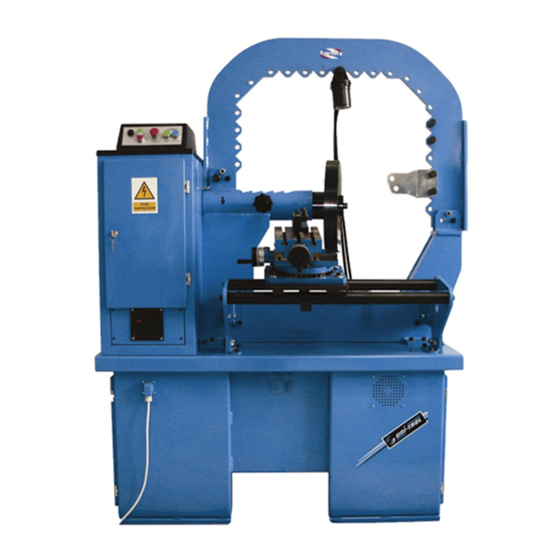
Page 8: Technical Description
10.0 TECHNICAL DESCRIPTION 10.1 GENERAL INFORMATION The machine is designed to repair of faults 10”-22” steel and aluminium rims. The rim repair is carried out by means of the hydraulic piston supplied with the suitable shaped working tools. The machine is supplied with a quick release hydraulic adapter to set the position and mount a rim securely. -
Page 10: Electrical System
10.3 ELECTRICAL SYSTEM The machine is adapted to alternating current of 3 x 400 V / 50 Hz. It is supplied with four-wire power supply cable; the green-yellow wire is a protective conductor while the other three wires are the phase conductors. The main power switch is located on the control box –... -
Page 11: General Protection Instructions
11.1 GENERAL PROTECTION INSTRUCTIONS Before operation of the wheel rim straightening machine, read attentively the following instructions: - Some rims require the use non-standard of centring rings or working tools. In order to provide correct operation and safety, non-standard spare parts must be re- supplied by the manufacturer (or the distributor) on the customer’s order against payment. - Page 12 Fig. 2. CONTROL PANELS 1. Emergency stop button 2. Hydraulic pump switch 3. Drive motor switch 4. Hydraulic adapter connecting (clamping) button 5. Hydraulic adapter disconnecting (loosening) button 6. Electrical system signal LED diode...
- Page 13 hydraulic pump oil level Fig. 3. Hydraulic pump...
-
Page 14: Mounting And Demounting System Operation
11.2 MOUNTING AND DEMOUNTING SYSTEM OPERATION (Figure 4) Wheel rim mounting: - Choose the proper mechanical pressure (Fig.4 no.1) for the rim which is going to be straightened. - On the spindle (Fig.4 no.2), slide the centring ring (Fig.4 no.3) with the outer diameter adapted to the diameter of central hole of rim. -
Page 15: Sensor
- Slide the rim until it leans on the flanche of adapter (Fig.4 no.4). - Slide the mechanical pressure (Fig.4 no.1) on the spindle (Fig.4 no.2) until the bolts (Fig.4 no.6) are set in the holes of the screws which fix the wheel to the car’s hub. - Put the washer (Fig.4 no.7) on the spindle (the flat side to mechanical pressure) between the mechanical pressure and the nut of adapter (Fig.4 no.8). - Page 17 1. Machine’s frame 2. Straightening piston 3. Support 4. Lever 5. Spreading hook 6. Bolt Fig. 5. Hook device 13.0 Accessories – standard equipment...
- Page 18 No. Name Amount Preliminary straightening lever S-shaped tool Angle tool Hammer tool Locking washer Magnetic mount Scriber I=63 mm I=188 mm 10 Rod I=88 mm 11 Rod I=113 mm 12 Middle rod I=96 mm 13 Middle rod I=174 mm 14 Centring ring D=64 mm 15 Centring ring D=63.3 mm...
-
Page 19: Health And Safety Regulations
14.0 HEALTH AND SAFETY REGULATIONS during operation of the straightening machine General remarks 1. You can operate the straightening machine on your own only if: - you have completed the right professional training; - you have completed the training in general and fire regulations, as well as the job position training;... -
Page 20: Electrical System Scheme
Basic operations before the straightening machine operation An operator of the straightening machine should: - read the detailed manual instruction; - listen to the commands and instructions of the professional supervisor concerning safe and correct task fulfilment; - consider how to work safely to fulfil one’s task; - prepare necessary helpful workshop equipment, tools, personal protectors (if necessary);... - Page 21 12. RELAY CONTROL TIME RELAY 13. FAN 14. RECTIFIER 15. EMERGENCY STOP BUTTON ( ENERGIA STOP) 16. WARNING LIGHT 17. TRANSFORMER 400 V / 24 V 18. MAIN SWITCH...
- Page 22 Fig. 6. Electrical system scheme CAUTION: The following control parts used twice in the straightening machine are not shown in the scheme: 5 – hydraulic pump switch 9 – hydraulic adapter demounting switch 10 – hydraulic adapter mounting switch 15 – emergency stop (ENERGIA STOP)
-
Page 23: Hydraulic System Scheme
16.0 HYDRAULIC SYSTEM SCHEME 1. Filter 2. Motor – pump assembly 3. Monoblock two-chamber hydraulic divider 4. Rotating joint 5. Adapter servo-motor 6. Straightening piston Fig. 7. Hydraulic system scheme of the straightening machine with the monoblock two-chamber hydraulic divider... -
Page 24: Picture Catalogue Of Spare Parts
17. Picture catalogue of spare parts Working tools S-shaped working tool Angle working tool Hammer working tool Rods for working tools Middle rod l=178 Middle rod l=96... - Page 25 17. Picture catalogue of spare parts LIMIT measurement support Scriber (magnetic mount) Preliminary Nut of adapter Locking washer straightening M27x2 lever...
- Page 26 17. Picture catalogue of spare parts...
- Page 27 17. Picture catalogue of spare parts...
- Page 28 17. Picture catalogue of spare parts...
- Page 29 The technical documentation mentioned product, as specified in Annex VII A, point 1 of the Machinery Directive, is located in the headquarters Uni-trol Ltd. (address as above) and will be made available to the competent national authorities for at least ten years from the date of the last piece.
Need help?
Do you have a question about the PO-22H and is the answer not in the manual?
Questions and answers