
Related Manuals for UNI-TROL TROLL MICRO M


Summary of Contents for UNI-TROL TROLL MICRO M
- Page 1 Operation and Maintenance Manual Wheel Balancer Model TROLL MICRO M Manufacturing – Sales – Maintenance „UNI-TROL” Sp. z o.o. ul. Estrady 56 01-932 Warszawa tel/fax (0-22) 817 94 22, 834 90 13,834 90 14...
- Page 2 Operation and Maintenance Manual Wheel Balancer for Motobike Wheels MODEL TROLL MICRO M Serial number: Manufacturing year: MANUFACTURER: „UNI-TROL” Sp. z o. o. ul. Estrady 56 01-932 Warszawa tel/fax (0-22) 817 94 22, 834 90 13,834 90 14 AUTHORISED SERVICE CENTRE UNI - TROL Sp.
-
Page 3: Table Of Contents
CONTENTS 1. PACKAGING, TRANSPORTATION, STORAGE ............ 4 2. INTRODUCTION ....................5 3. MACHINE DESCRIPTION ..................8 4. SAFETY ........................ 10 5. INSTALLATION ....................12 6. PROGRAMMES ....................15 6.1 Balancer Computer Software ................15 6.1.1 WIDTH ......................15 6.1.2 OFF-SET ...................... 16 6.1.3 DIAMETER .................... -
Page 4: Packaging, Transportation, Storage
THE MANUFACTURER RESERVES THE RIGHT TO MAKE MODERNIZATION CHANGES TO ITS PRODUCT WITHOUT ANY OBLIGATION TO MAKE SUCH CHANGES IN THIS MANUAL. 1.PACKAGING, TRANSPORTATION, STORAGE ATTENTION ! Any operations related to packaging, lifting, moving, transportation and unpacking must be performed only by qualified staff. Packaging The wheel balancer is dispatched as a complete machine (quick adapter, casing, wheel balancer). -
Page 5: Introduction
2. INTRODUCTION WARNING This manual is addressed to workshop staff who are authorised to operate a wheel balancer (an operator) as well as to workers performing on-going maintenance; read this manual thoroughly before starting unpacking and operation of the wheel balancer. The manual contains important information concerning PERSONAL SAFETY of operators and maintenance workers, OPERATION OF THE WHEEL BALANCER. - Page 6 - PN-EN 50419 -1:2008 Marking of electrical and electronic equipment in accordance with Article 11 (2) of Directive 2002/96/CE (WEEE) - PN-EN 61190-1 -3:2008 Materials for connecting electronic components - Part 1-3: Particular requirements for solders for electronic applications and solders with fluxes or without fluxes for soldering electronic components .
- Page 7 Technical data: - max. wheel diameter 0,9 m - rim diameter 10" - 30" - rim width 2" - 15" - balancing accuracy - measuring time 6-7 s - balancer’s weight 60 kg - dimensions: - with hood opened 880x800x1400mm - with hood closed 880x550x1080mm - max.
-
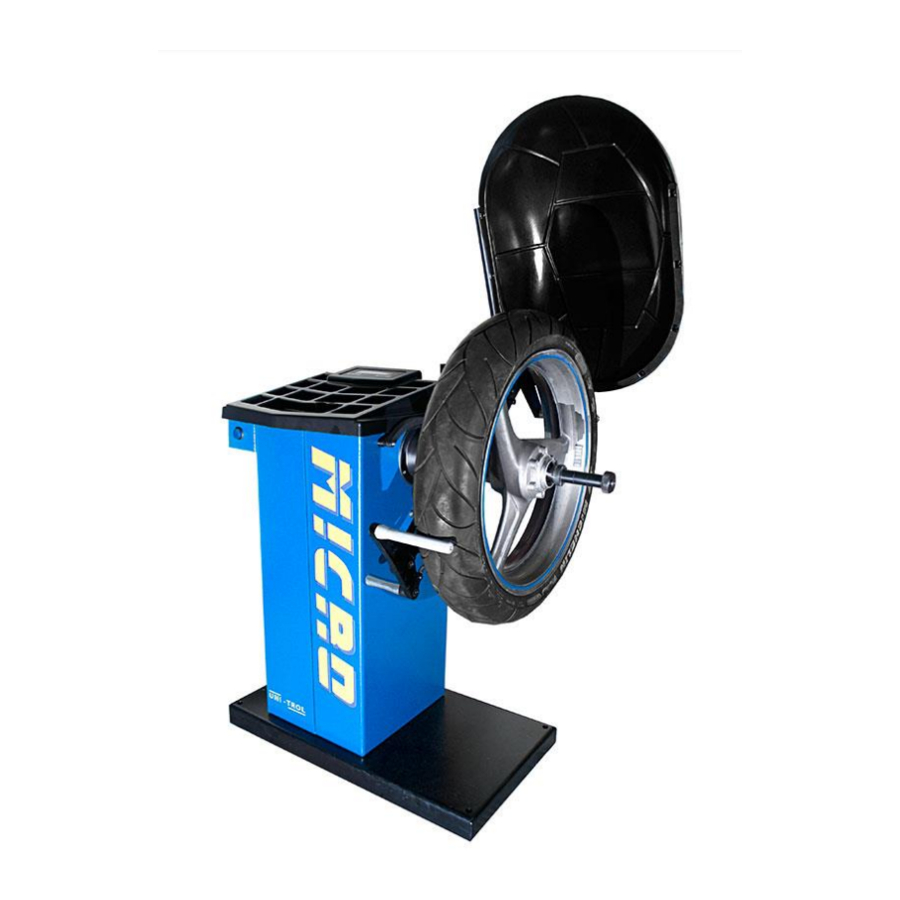
Page 8: Machine Description
MACHINE DESCRIPTION The wheel balancer TROLL – MICRO M serves for motorbike wheels dynamic balancing within one measuring cycle. 1. Switch on/off 2. Adjuster 3. Rubber pads (4 pcs) 4. Motorbike adapter 5. Keyboard 6. Hood 7. Calibration device... - Page 9 Fig.1 Wheel balancer parts. Fig.2 Keyboard Keys: Wheel parameters selection Blancing programme selection dynamic-static* Wheel parameters: off-set, diameter, width Balancing accuracy Measuring cycle stop [STOP] Measuring cycle start [START] Imbalance recalculating Calibration Hidden-weight programme Memory M1 – M2 * programme 1: adhesive weights programme 2: static balancing ( for thin rims, by one weight) Sound signal confirms button pressing.
-
Page 10: Safety
Explanations concerning threats and hazards that may occur during operation and maintenance of the wheel balancer as well as general and specific precautions intended to eliminate the potential dangers are provided below. Before starting work with TROLL MICRO M, it is necessary to read carefully and understand these instructions. ATTENTION ! - Page 11 Electric shock risk — a specific caption placed on the machine where there is particularly high risk of electric shock. Hazards for staff The paragraph describes possible threats for the operator or any other people present near the wheel balancer caused by its improper use. Risk of hitting There is a risk of hitting the component of the machine.
-
Page 12: Installation
Never exceed admissible weight capacity of the balancer — i.e. 60 kg. IMPORTANT ! Every use of the wheel balancer in a manner contrary to its intended purpose shall entail the danger of causing serious injuries and accidents. Therefore, it is particularly significant to strictly apply any and all recommendations concerning operation, maintenance and safety, stipulated in this manual. - Page 13 Adapter mounting. Before mounting the adapter, it is necessary to clean thoroughly the cone areas of shaft and adapter with an oil-wetted cloth. Mount the adapter onto the shaft and tighten up the adapter to the shaft with the use of screw. Fig.3.
- Page 14 Wheel mounting on adapter. (Fig.4.) Center the wheel in conus sleeves (4) and block by distance sleeves (5) and nut (6). Eventually the wheel is fixed by tyre tighters (2). Electrical connection of the wheel balancer ATTENTION ! Plug the supply cable into the socket 230V/50Hz. ATTENTION ! SINCE UNEXPECTED WARMING OF FROZEN METAL AND PLASTIC SOLID GENERATES CONSIDERABLE QUANTITIES OF WATER VAPOUR CONDENSATE, IT IS...
-
Page 15: Programmes
1. Hood 2. Hood holder 3. M6 x 15 4. Socket Fig. 5 Hood mounting. 5. M8 x 80 6. Distance 6. PROGRAMMES. 6.1 Balancer Computer Software. Switch the balancer on. After control test and signal sound display shows 6.1.1 WIDTH. Press D until the display show (<->) and last entered width. -
Page 16: Off-Set
6.1.2 OFF-SET. Press D until the display show set-off symbol and its last entered value. Move adjuster’s head (1) to rim (4) (Fig.10). Adjuster’s nonius show the set-off value (3). Insert this value pressing (+) or (-). 6.1.3 DIAMETER. Press D until the display show diameter symbol and its last entered value. Pressing (+) or (-) we change this parameter one inch from 10 till 30. -
Page 17: Balancing Programme Selection
6.1.4 Balancing programme selection. Press . On display marker stops in front of pictogram (a) or (b). Select the programme by pressing Variant a) Dynamic balancing by two adhesive weights. Variant b) Static balancing (for thin rims by one weight). This variant is not recommended for wheels wider than 2,5”. -
Page 18: Balancer Drive
6.1.7 Balancer drive. - Manual start. . If we don’t close the hood the display shows CASE. The drive starts when hood is Press closed and key pressed. Display shows pictogram of cycle start. When the display shows measuring result and the spindle stops the cycle is finish. - Automatic start. - Page 19 After attaching weights of particular weight in particular positions perform a control measurement. In theory, the indicator should now display two zeros meaning that the remaining volume of imbalance does not exceed No 5 g, according to the set cut-off threshold.
- Page 20 If new position of imbalance is the same as the previous one or it differs to only a small extent, the weight should be larger. 1 – weight 2 – new correction position...
- Page 21 If the new position of imbalance is exactly at the opposite side of the previously attached weight, or it is slightly moved from this point, the weight should be decreased. 1 – weight 2 – new correction position If previously attached weight is below the new correction position, it should be moved upwards.
- Page 22 It is difficult to clearly identify by what distance the weight should be moved in order to correct the residual imbalance. It depends on the value of imbalance to be corrected as well as the dimensions and position of the mounted weight. In general, it can be said that large weight and residual imbalance requires minor correction of the position.
-
Page 23: Imbalance Recalculation
6.2.1 Imbalance recalculation This function enables to quickly obtain the correct values of imbalance in the event when the measurement was performed upon entry of incorrect parameters of a wheel. Example: Incorrect data regarding the wheel to be balanced are entered to the machine’s memory. -
Page 24: Calibration With Calibrating Device
3.4 Spin the wheel to the right to the position defined in point 3.1 until the spoke where weight can be placed. To accept this position press (+) . This is a point where correcting weight of 15 g should be placed. 3.5 Spin the wheel to the left until the place defined in point 3.3. - Page 25 1. Calibration device screwed to tighter 2. Calibration device position Fig.10 Calibrating device mounting 3. Press and hold (display shows CAL!) until sound signal and the pictogram will switch the balancer’s drive on. shown below. Release 4. Calibrating cycle finish when display shows figures: 0 and 59 or 0 and 60. ATTENTION ! If display shows other figures that means wrong calibration –...
-
Page 26: Calilbration With Wheel
6.3.1 CALIBRATION WITH A WHEEL 1. Use accurately balanced wheel with known parameters. Enter into the memory wheel DIAMETER, WIDTH, OFF-SET. Select programme ALU-1. 2. Place weight of 60 g on the outer rim side 3. Press and release , then press and hold until sound signal and pictogram shown below. -
Page 27: Scrapping
PERIODIC MAINTENANCE In order to maintain the wheel balancer in good technical condition, it is recommended to comply with the following instructions. FAILURE TO APPLY THESE RECOMMENDATIONS SHALL ABSOLVE THE MANUFACTURER FROM ANY LIABILITY STIPULATED IN THE GUARANTEE. 1. Clean the wheel balancer at least once a month without using chemical cleaning agents and high pressure spray guns.
Need help?
Do you have a question about the TROLL MICRO M and is the answer not in the manual?
Questions and answers