
Related Manuals for 4BARCODE Technology 4B-2044A Series

Summary of Contents for 4BARCODE Technology 4B-2044A Series
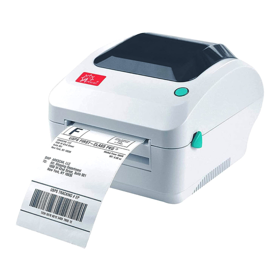
- Page 1 4B-2044x/ 4B-2054x/4B-2064x/ 4B-3034x/ 4B-3044x Series DIRECT THERMAL BARCODE PRINTER USER’S MANUAL...
-
Page 2: Table Of Contents
Contents ....................... 1 OPYRIGHT ECLARATION ......................... 1 OMPLIANCES 1. Introduction ......................... 3 2. Getting Started ......................3 2.1 Unpacking and Inspection ..................3 2.2 Equipment Checklist ....................3 2.3 Printer Parts......................5 2.3.1 Front View ....................... 5 2.3.2 Rear View ......................5 3 Setup .......................... - Page 3 LED Status ....................31 Print Quality ....................31 7. LED and Button Operation..................33 7.1 LED ........................33 7.2 Button Operation ....................33 Revise History ....................... 36...
-
Page 4: Copyright Declaration
Information in this subject to change without notice and does not represent a commitment on the part of 4BARCODE Technology Co., Ltd... No part of this manual may be reproduced or transmitted in any form by any means, for any purpose other than the purchaser’s personal use, without the expressed written permission of 4BARCODE... - Page 5 CAUTION 1. THE MAIN BOARD INCLUDES REAL TIME CLOCK FEATURE HAS LITHIUM BATTERY CR2032 INSTALLED. RISK OF EXPLOSION IF BATTERY IS REPLACED BY AN INCORRECT TYPE. 2. DISPOSE OF USED BATTERIES ACCORDING TO THE MANUFACTURER INSTRUCTIONS.
-
Page 6: Introduction
Introduction Thank you for purchasing the 4BARCODE 4B-2044A/ 4B-2054A/ 4B-3034A/ 4B-3044A Series Direct Thermal BarCode Printer. Although it is a compact desktop printer, it is reliable and with Superior throughput performance. This printer provides direct thermal printing at user selectable speed of: 2.0, 3.0, 4.0, 5.0, inches per second. - Page 7 Dealer option Peel off module assembly. Main board integrated with internal Ethernet Internal Ethernet print server module User option PEEL module External roll mount, media OD. 214 mm (8.4”) with 3” core label spindle ...
-
Page 8: Printer Parts
2.3 Printer Parts 2.3.1 Front View Clear Window Top Cover LED Indicator Feed Button Label Opening Top Cover Open Lever Backing Paper Opening Front Panel 2.3.2 Rear View 1. Ethernet Interface 2. SD Card 3. USB Interface 4. RS-232C DB-9 Interface 5. -
Page 9: Setup
3 Setup 3.1 Setting Up the Printer 1. Place the printer on a flat, secure surface. 2. Make sure the power switch is off. 3. Connect the printer to the computer with the RS-232 or USB cable. 4. Plug the DC power cord into the power jack at the rear of the printer, and then plug the AC power cord into a properly grounded receptacle. -
Page 10: Loading Label Stock
3.2 Loading Label Stock 1. Insert a 1” label spindle into a paper roll (If your paper core is 1 inch, remove the 1.5 inch core adapter from the fixing tab). Label Roll 1.5” Core Adapter Fixing Tab Printing Side Face up 1”... - Page 11 6. Close the printer cover slowly and make sure the cover locks levers securely.
-
Page 12: Peel-Off Installation Assembly (Option)
Peel-Off Installation Assembly (Option) Open the top cover. Unscrew the 4 screws in the lower inner cover. Screws Screws... - Page 13 Hold the lower cover and lift up the top cover opening levers to separate the lower inner cover from the lower cover. Lower inner cover Lower cover Thread the harness red connector through the cable hole at the front side of lower inner cover.
-
Page 15: Loading Label For Peel-Off Mode (Option)
3.4 Loading Label for Peel-off Mode (Option) 1. Open the peel-off module by pulling it out. Peel-off Roller Peel-off Panel 2. Thread the label, printing side facing up, through the label guides and place it on top of the platen. 3. -
Page 17: External Label Roll Mount Installation (Option)
3.5 External Label Roll Mount Installation (Option) 1. Attach an external label roll mount on the bottom of the printer. 2. Install a roll of label on the external label roll mount. Label External Label Roll Mount 3. Feed the label to the external label feed opening through the rear label guide. External Label Feed Opening Rear Label Guide... -
Page 18: Diagnostic Tool
3.6 Diagnostic Tool The Diagnostic Utility is a toolbox that allows users to explore the printer’s settings and status; change printer settings; download graphics, fonts, and firmware; create printer bitmap fonts; and to send additional commands to the printer. Using this convenient tool, you can explore the printer status and settings and troubleshoot the printer. -
Page 19: Printer Function (Calibrate Sensor, Ethernet Setup, Rtc Setup
3.6.2 Printer Function (Calibrate sensor, Ethernet setup, RTC setup………) 1. Select the PC interface connected with barcode printer. 2. Click the “Function” button to setting. 3. The detail functions in the Printer Function Group are listed as below. Function Description Calibrate the sensor specified in the Printer Calibrate Sensor Setup group media sensor field... -
Page 20: Setting Ethernet By Diagnostic Utility (Option)
3.7 Setting Ethernet by Diagnostic Utility (Option) The Diagnostic Utility is enclosed in the CD disk \Utilities directory. Users can use Diagnostic Tool to setup the Ethernet by RS-232, USB and Ethernet interfaces. The following contents will instruct users how to configure the Ethernet by these three interfaces. -
Page 21: Using Rs-232 Interface To Setup Ethernet Interface
3.7.2 Using RS-232 interface to setup Ethernet interface 1. Connect the computer and the printer with a RS-232 cable. 2. Turn on the printer power. 3. Start the Diagnostic Utility by double clicks on the icon. 4. Select “COM” as interface then click on the “Setup” button to setup the serial port baud rate, parity check, data bits, stop bit and flow control parameters. -
Page 22: Using Ethernet Interface To Setup Ethernet Interface
3.7.3 Using Ethernet interface to setup Ethernet interface 1. Connect the computer and the printer to the LAN. 2. Turn on the printer power. 3. Start the Diagnostic Utility by double clicks on the icon. 4. Select “Ethernet” as the interface then click on the “Setup” button to setup the IP address, subnet mask and gateway for the on board Ethernet. - Page 23 The default IP address is obtained by DHCP. To change the setting to static IP address, click “Static IP” radio button then enter the IP address, subnet mask and gateway. Click “Set IP” to take effect the settings. Users can also change the “Printer Name” by another model name in this fields then click “Set Printer Name”...
-
Page 24: Install Memory Card
3.8. Install Memory Card 1. Upside down the printer. 2. Remove 1 screw and open the memory card cover. Memory Card Cover... -
Page 25: Power On Utilities
4. Power on Utilities There are six power-on utilities to set up and test printer hardware. These utilities are activated by pressing FEED button and by turning on the printer power simultaneously. The utilities are listed as below: Gap/Black mark sensor calibration Gap/black mark sensor calibration, Self-test and Dump mode Printer initialization Skip AUTO.BAS... -
Page 26: Gap/Black Mark Calibration, Self-Test, Dump Mode
4.2 Gap/Black Mark Calibration, Self-test, Dump Mode While calibrate the gap/black mark sensor, printer will measure the label length, print the internal configuration (self-test) and then enter the dump mode. Please follow the steps as below. 1.Turn off the power switch. 2. - Page 27 Self-test Printer will print the printer configuration after gap/black mark sensor calibration. Self-test printout can be used to check if there is any dot damage on the heater element, printer configurations and available memory space. Self-test printout Print head check pattern Model name and F/W version Printed mileage (meter) Firmware checksum...
- Page 28 Note: 1. The physical flash memory for RoHS compliant version is 4MB Flash and 8MB SDRAM (4BARCODE 4B-2044A/ 4B-2054A/ 4B-3034A/ 4B-3044A Model) 2. System occupies 4096 KB in Flash memory so total flash memory space for user downloading is 2560 KB 3.
- Page 29 Dump mode Printer will enter dump mode after printing printer configuration. In the dump mode, all characters will be printed in 2 column s as following. The left side characters are received from your system and right side data are the corresponding hexadecimal value of the characters.
-
Page 30: Printer Initialization
4.3 Printer Initialization Printer initialization is used to clear DRAM and restore printer settings to defaults. The only one exception is ribbon sensitivity, which will note be restored to default. Printer initialization is activated by the following procedures. 1. Turn off the power switch. 2. -
Page 31: Skip Auto.bas
4.4 Skip AUTO.BAS TSPL2 programming language allows user to download an auto execution file to flash memory. Printer will run the AUTO.BAS program immediately when turning on printer power. The AUTO.BAS program can be interrupted without running the program by the power-on utility. -
Page 32: Maintenance
5. Maintenance 5.1 Cleaning This session presents the clean tools and methods to maintain your printer. Please use one of following material to clean the printer. Cotton swab (Head cleaner pen) Lint-free cloth Vacuum / Blower brush ... - Page 33 cloth Interior Brush or vacuum As needed Note: Do not touch printer head by hand. If you touch it careless, please use ethanol to clean it. Please use medicinal alcohol. Do not use industrial alcohol, industrial alcohol may damage the print head. ...
-
Page 34: Troubleshooting
6. Troubleshooting The following guide lists the most common problems that may be encountered when operating this barcode printer. If the printer still does not function after all suggested solutions have been invoked, please contact the Customer Service Department of your purchased reseller or distributor for assistance. -
Page 35: Print Quality
Print Quality `Problem Possible Cause Recovery Procedure Check if interface cable is well Re-connect cable to interface. connected to the interface connector. The serial port cable pin configuration Please replace the cable with pin to is not pin to pin connected. pin connected. -
Page 36: Led And Button Operation
7. LED and Button Operation This printer has one button and one three-color LED indicator. By indicating the LED with different color and pressing the button, printer can feed labels, pause the printing job, select and calibrate the media sensor, print printer self-test report, reset printer to defaults (initialization). - Page 37 Gap/Black Mark 1. Turn off the power switch. Sensor Calibration 2. Hold on the button then turn on the power switch. 3. Release the button when LED turns red after 5 green/amber blinks. (Any red/amber will do during the 5 blinks).
- Page 38 Printer 1.Turn off the power switch. Initialization 2. Hold on the button then turn on the power switch. 3 Release the button when LED becomes bule and blinking. (Any red will do during the 5 blinks). It will calibrate the gap/black mark sensor sensitivity. ...
-
Page 39: Revise History
Revise History Date Content Editor * Release V1.00 Austin Bill 2017/01/16...
Need help?
Do you have a question about the 4B-2044A Series and is the answer not in the manual?
Questions and answers