
Related Manuals for JESS WELDING conMIG 300


Summary of Contents for JESS WELDING conMIG 300
- Page 1 J ä c k l e & E s s S y s t e m G m b H DE Betriebsanleitung EN Operating instructions conMIG 300 DE Schweißstromquelle EN Welding power source www.jess-welding.com...
-
Page 2: Table Of Contents
Schweißbrenner mit Display DE-20 Lieferumfang DE-8 Transport DE-8 Wartung und Reinigung DE-21 Lagerung DE-8 Störungen und deren Behebung DE-21 Funktionsbeschreibung DE-8 Anhang DE-23 Inbetriebnahme 14.1 Ersatzteile DE-23 DE-9 Netzanschluss DE-10 14.2 Schaltplan conMIG 300 DE-27 DE - 1 BA-0001 • 2020-12-01... -
Page 3: Identifikation
300 1 Identifikation 1 Identifikation MIG/MAG Schweißanlage conMIG 300 zum Schweißen von Dünnblech (KFZ) bis zu dicken Materialien sowie Edelstahl und Aluminium. 1.1 Kennzeichnung Das Produkt erfüllt die geltenden Anforderungen des jeweiligen Marktes für das Inverkehrbringen. Sofern es einer entsprechenden Kennzeichnung bedarf, ist diese am Produkt angebracht. -
Page 4: Klassifizierung Der Warnhinweise
2 Sicherheit conMIG 300 2.5 Klassifizierung der Warnhinweise Die in der Betriebsanleitung verwendeten Warnhinweise sind in vier verschiedene Ebenen unterteilt und werden vor potentiell gefährlichen Arbeitsschritten angegeben. Geordnet nach abnehmender Wichtigkeit bedeuten sie Folgendes: GEFAHR Bezeichnet eine unmittelbar drohende Gefahr. Wenn sie nicht gemieden wird, sind Tod oder schwerste Verletzungen die Folge. -
Page 5: Warn- Und Hinweisschilder
300 2 Sicherheit 2.7 Warn- und Hinweisschilder Am Produkt befinden sich folgende Warn- und Hinweisschilder: Symbol Bedeutung Betriebsanleitung lesen und beachten! Vor dem Öffnen Netzstecker ziehen! Warnung vor heißer Oberfläche 2.8 Angaben für den Notfall Unterbrechen Sie im Notfall sofort folgende Versorgungen: •... -
Page 6: Produktbeschreibung
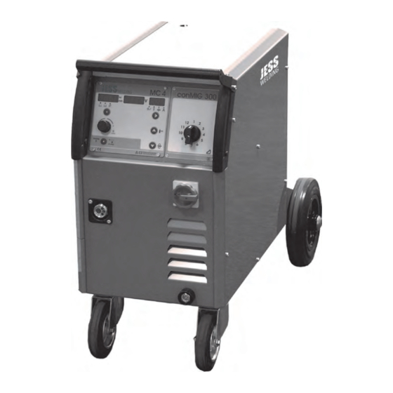
3 Produktbeschreibung conMIG 300 3 Produktbeschreibung 3.1 Technische Daten Abb. 1 Technische Daten conMIG 300 conMIG 300 Tab. 1 Technische Daten conMIG 300 Stromquelle conMIG 300 Netzspannung 50/60 Hz 400 V, 3 Phasen, +/− 10 % Stromaufnahme Imax = 19 A, Ieff = 11 A Sicherung 16 A träge... -
Page 7: Umgebungsbedingungen
Mengen an Staub, Säuren, korrosiven Gasen oder Substanzen usw. sein, soweit diese nicht beim Schweißen entstehen. 3.3 Typenschild Die Schweißstromquelle ist am Gehäuse mit einem Typenschild wie folgt gekennzeichnet: Abb. 2 Typenschild conMIG 300 3.4 Verwendete Zeichen und Symbole Symbol Beschreibung •... -
Page 8: Lieferumfang
4 Lieferumfang conMIG 300 4 Lieferumfang Tab. 2 Lieferumfang conMIG 300 • Schweißstromquelle • Betriebsanleitung • Beipackzettel „allgemeine Sicherheitsinformationen“ Ausrüst- und Verschleißteile separat bestellen. Bestelldaten und Identnummern der Ausrüst- und Verschleißteile entnehmen Sie den aktuellen Bestellunterlagen. Kontakt für Beratung und Bestellung finden Sie im Internet unter www.jess-welding.com. -
Page 9: Inbetriebnahme
300 6 Inbetriebnahme Steuerungsfunktionen Drahtvorschub und Punktzeit einstellbar Kühlung der Stromquelle durch geräuscharmen Ventilator Der Ventilator wird über einen Thermostat eingeschaltet und läuft erst, wenn sich die Stromquelle erwärmt hat. In den Schweißpausen schaltet der Ventilator ab, sobald die Stromquelle wieder abgekühlt ist. -
Page 10: Netzanschluss
6 Inbetriebnahme conMIG 300 Achten Sie bei der Aufstellung auf ausreichenden Platz für Eintritt und Austritt der Kühlluft, damit die angegebene Einschaltdauer erreicht werden kann. Die Anlage nicht Nässe, Schweißspritzern und dem direkten Funkenstrahl bei Schleifarbeiten aussetzen. Die Anlage nicht im Freien bei Regen einsetzen. -
Page 11: Übersicht Steuerungsfunktionen
300 7 Übersicht Steuerungsfunktionen 7 Übersicht Steuerungsfunktionen Tab. 3 Übersicht der Steuerungsfunktionen conMIG 300 und der erhältlichen Steuerboxen Funktion MC 3 MC 4 MC 5 MC 15 Stufengeschaltete Schweißanlage (conMIG) Handbetrieb ... -
Page 12: Betrieb
8 Betrieb conMIG 300 8 Betrieb HINWEIS • Jegliche Arbeiten am Gerät bzw. System sind ausschließlich befähigten Personen vorbehalten. 8.1 Steuerungsfunktionen 8.1.1 Steuerung MC 3 Abb. 4 Steuerbox MC 3 Anzeige-Display Spannung (V) Drahteinfädeltaste / speichern Auswahl Schweißfunktionen G Anzeige Hand- Automatikbetrieb... - Page 13 300 8 Betrieb Pos. Beschreibung Bedientaste Auswahl Schweißart. 2-Takt, 4-Takt, 2-Takt - Punkten oder Sonderfunktion. LED-Anzeige aktive Schweißart. 2-Takt, 4-Takt, 2-Takt - Punkten oder Sonderfunktion. Anzeige-Display Drahtgeschwindigkeit in m/min. bzw. Korrektur von −50 % bis +50 % der Drahtgeschwindigkeit. Blinkender Punkt: HOLD Funktion aktiv.
-
Page 14: Steuerung Mc
8 Betrieb conMIG 300 Pos. Beschreibung Bedientaste Auswahl Schweißart. 2-Takt, 4-Takt, 2-Takt - Punkten. LED-Anzeige aktive Schweißart. 2-Takt, 4-Takt, 2-Takt - Punkten. Anzeige-Display Drahtgeschwindigkeit in m/min. bzw. Korrektur von −50 % bis +50 % der Drahtgeschwindigkeit. Blinkender Punkt: HOLD Funktion aktiv. -
Page 15: Steuerung Mc
300 8 Betrieb 8.1.4 Steuerung MC 15 Abb. 7 Steuerbox MC 15 Einstellung Auswahl Schweißart Drahteinfädeln Einschleichgeschwindigkeit Drehknopf Parametereinstellung Anzeige-Display Parameter Einstellung Drahtrückbrand Pos. Beschreibung Bedientaste Einstellung der Einschleichgeschwindigkeit (Startgeschwindigkeit). Taste drücken und mittels Drehknopf (Pos. D) den gewünschten Wert einstellen. Einstellbereich: 10–100 % der Schweißgeschwindigkeit. -
Page 16: Beschreibung Der Steuerungsfunktionen
8 Betrieb conMIG 300 8.2 Beschreibung der Steuerungsfunktionen 2-Takt, 4-Takt, Punkten, Sonderprogramme (MC 3–MC 5) Durch Tippen auf die Bedientaste (L) kann zwischen 2-Takt, 4-Takt, 2-Takt Punkten und eventuellen Sonderfunktionen umgeschaltet werden. Die jeweils aktivierte Funktion wird durch die LED angezeigt. - Page 17 300 8 Betrieb Funktionen (MC 4–MC 5) Im Ruhezustand (wenn nicht geschweißt wird): ► Durch kurzes Antippen der Bedientaste können folgende Funktionen für jede Schweißkurve individuell eingestellt werden: • Startgeschwindigkeit: 10 bis 100 % der Schweißgeschwindigkeit • Drahtrückbrand: −90 ms bis +60 ms ▲...
-
Page 18: Materialtabelle
9 Materialtabelle conMIG 300 Im rechten Display steht die Jobnummer. Nachdem das Jobmenü geöffnet ist, kann mit dem mittleren Drehknopf der gewünschte Speicherplatz ausgewählt werden. Nun kann man entweder einen bereits abgespeicherten Job durch Tippen der Bedientaste „JOB laden“ laden, oder durch Tippen auf die Bedientaste „speichern“... -
Page 19: Drahtvorschub
300 10 Drahtvorschub 10 Drahtvorschub 10.1 Wechseln der Drahtvorschubrolle Abb. 8 Wechseln der Drahtvorschubrolle HINWEIS • Passende Nut für den jeweiligen Drahtdurchmesser verwenden. Rändelschraube (F) herausdrehen. Darauf achten, dass die Nut der Drahtvorschubrolle eine Flucht zu den Drahtführungsrohren (E) bildet. -
Page 20: Schweißbrenner Mit Display
11 Schweißbrenner mit Display conMIG 300 11 Schweißbrenner mit Display HINWEIS Brenner nur bei ausgeschalteter Maschine wechseln! Tab. 5 Funktionen nach Steuerbox sortiert ■ ■* ■ ■ ■ ■ ■ ■ ■ MC 3 MC 4 ■ ■* ■ ■... -
Page 21: Wartung Und Reinigung
300 12 Wartung und Reinigung Beispiel: Job 1 - frei, Job 2 - MIG 160 A, Job 3 - Power 250 A, Job 4 - MIG 100 A, Job 5 - frei In diesem Beispiel kann jetzt mit den Tasten +/− während des Schweißens zwischen Job 2, 3 und 4 beliebig gewechselt werden. - Page 22 13 Störungen und deren Behebung conMIG 300 Tab. 6 Störungen und deren Behebung Störung / Fehler mögliche Ursache Hilfe Display-Anzeige • Umgebungstemperatur unter −10 °C bzw. • Maschine in normalen Temperaturbereich über +40 °C bringen T°C - int - z.B. +56 •...
- Page 23 300 14 Anhang 14 Anhang 14.1 Ersatzteile Abb. 9 Frontansicht conMIG 300 Tab. 7 Ersatzteile conMIG 300 außen Pos. Bezeichnung Artikel-Nr. Seitenblech rechts 715.040.055 Handgriff klein 305.044.002 Frontfolie conMIG 300 304.040.051 12-Stufenschalter 440.025.103 Schaltergriff, schwarz 440.220.051 Hauptschalter 440.233.010 Einbaubuchse BEB 35-5 422.031.024...
- Page 24 14 Anhang conMIG 300 Abb. 10 Seitenansicht conMIG 300 DE - 22 BA-0001 • 2020-12-01...
-
Page 25: Anhang
300 14 Anhang Tab. 8 Ersatzteile conMIG 300 innen Pos. Bezeichnung Art.-Nr. Gleichrichter 6 Platte, 6 Dioden / Platte 461.200.016 Magnetventil 42V NW 2,5 465.018.009 Schütz DL4K-14, 42V 442.042.011 Kabelverschraubung M25 × 1,5 420.025.001 Gegenmutter Kabelvers. M25 × 1,5 420.025.002... -
Page 26: Ersatzteile
14 Anhang conMIG 300 Abb. 11 Ersatzteile Drahtvorschub Tab. 9 Ersatzteile Drahtvorschubmotor Pos. Bezeichnung Art.-Nr. Druckarm rechts komplett 455.042.001 Antriebsritzel 455.042.009 Drahtvorschubrolle 0,8 / 1,0 für Stahl 455.030.004 Drahtvorschubrolle 1,0 / 1,2 für Stahl 455.030.005 Drahtvorschubrolle 1,0 / 1,2 für Alu 455.030.003... - Page 27 300 14 Anhang 14.2 Schaltplan conMIG 300 Abb. 12 Schaltplan conMIG 300 BA-0001 • 2020-12-01 DE - 25...
- Page 28 14 Anhang conMIG 300 DE - 26 BA-0001 • 2020-12-01...
- Page 29 EN-8 Troubleshooting EN-21 Storage EN-8 Appendix EN-23 Functional description EN-8 14.1 Spare parts EN-23 conMIG 300 circuit diagram 14.2 EN-27 Putting into operation EN-9 Mains port EN-10 Overview of control functions EN-11 Welding EN-11 EN - 1 BA-0001 • 2020-12-01...
-
Page 30: Identification
300 1 Identification 1 Identification conMIG 300 MIG/MAG welding machine suitable for welding a range of materials from thin sheet metal (e.g. car parts) to thick materials as well as stainless steel and aluminium. 1.1 Marking This product fulfils the requirements that apply to the market to which it has been introduced. -
Page 31: Classification Of The Warnings
2 Safety conMIG 300 2.5 Classification of the warnings The warnings used in the operating instructions are divided into four different categories and are indicated prior to potentially dangerous work steps. Arranged in descending order of importance, they have the... -
Page 32: Warning And Information Signs
300 2 Safety 2.7 Warning and information signs The following warning and information signs can be found on the product: Symbol Meaning Read and observe the operating instructions! Disconnect the mains plug before opening! Warning against hot surfaces. 2.8 Emergency information In the event of an emergency, immediately disconnect the following supplies: •... -
Page 33: Product Description
3 Product description conMIG 300 3 Product description 3.1 Technical data Fig. 1 conMIG 300 technical data conMIG 300 Tab. 1 conMIG 300 technical data Power source conMIG 300 Mains voltage 50/60 Hz 400 V, 3 phase, ±10% Current consumption... -
Page 34: Ambient Conditions
3.3 Nameplate The welding power source is labelled with a nameplate on the housing as follows: Fig. 2 conMIG 300 nameplate 3.4 Signs and symbols used Symbol Description •... -
Page 35: Scope Of Delivery
4 Scope of delivery conMIG 300 4 Scope of delivery Tab. 2 conMIG 300 scope of delivery • Welding power source • Operating instructions • “General safety information” instruction leaflet Order the equipment parts and wear parts separately. The order data and ID numbers for the equipment parts and wear parts can be found in the current product catalogue. -
Page 36: Putting Into Operation
300 6 Putting into operation Welding voltage selection 12-step voltage selector switch Control functions Wire feeder and spot welding time can be adjusted Cooling the power source with a quiet fan The fan is activated by a thermostat and does not begin to operate until the power source has warmed up. -
Page 37: Mains Port
6 Putting into operation conMIG 300 NOTICE • Note the following instructions: See 3 Product description on page EN-4 • Only qualified personnel are permitted to perform work on the device or system. • Components must only be used in environments with sufficient ventilation. -
Page 38: Overview Of Control Functions
300 7 Overview of control functions 7 Overview of control functions Tab. 3 Overview of conMIG 300 control functions and the available control boxes Function MC 3 MC 4 MC 5 MC 15 Step-controlled welding machine (conMIG) ... -
Page 39: Operation
8 Operation conMIG 300 8 Operation NOTICE • Only qualified personnel are permitted to perform work on the device or system. 8.1 Control functions 8.1.1 MC 3 control system Fig. 4 MC 3 control box Voltage display (V) Wire feed button / save... -
Page 40: Mc 4 Control System
300 8 Operation Pos. Description Operating button for selecting the welding type: 2-step, 4-step, 2-step spot or custom function. LED indicator for the active welding type: 2-step, 4-step, 2-step spot or custom function. Display for wire speed in m/min and wire speed adjustment by −50% to +50%. Flashing dot: HOLD function active. -
Page 41: Mc 5 Control System
8 Operation conMIG 300 8.1.3 MC 5 control system Fig. 6 MC 5 control box Display for current (A) or Parameter selection switch G LED indicator for the active voltage (V) Gas test / increase parameter welding type H Welding type selector... -
Page 42: Mc 15 Control System
300 8 Operation 8.1.4 MC 15 control system Fig. 7 MC 15 control box Knob for setting the creep speed Welding type selector Wire feed Knob for setting the wire burn-back Knob for parameter settings Parameter display Pos. Description Operating button for setting the creep speed (start speed). -
Page 43: Description Of The Control Functions
8 Operation conMIG 300 8.2 Description of the control functions 2-step, 4-step, spot, custom programmes (MC 3 – MC 5) Tap the operating button (L) to switch between 2-step, 4-step, 2-step spot and possibly custom functions. The activated function is indicated by the LEDs. - Page 44 300 8 Operation Functions (MC 4 – MC 5) In idle mode (when not welding): ► Briefly tap the operating button to individually set the following functions for each welding curve: • Start speed: 10% to 100% of the welding speed •...
-
Page 45: Material Table
9 Material table conMIG 300 Deleting jobs/resetting the control system to the factory settings (MC 3) The control system has two separate options: • 1. Delete all jobs saved by the user (display: ‘rES 1 – Job’) or • 2. Reset the entire control system to the factory settings (display: ‘rES 2 – ALL’). -
Page 46: Wire Feeder
300 10 Wire feeder 10 Wire feeder 10.1 Replacing the wire feed roller Fig. 8 Replacing the wire feed roller NOTICE • Use a suitable groove for the respective wire diameter. Unscrew the knurled screw (F). Ensure that the groove in the wire feed roller is aligned with the wire guide tube (E). -
Page 47: Welding Torch With Display
11 Welding torch with display conMIG 300 11 Welding torch with display NOTICE • Only replace the torch when the machine is switched off! Tab. 5 Functions sorted by control box ■ ■* ■ ■ ■ ■ ■ ■ ■... -
Page 48: Maintenance And Cleaning
300 12 Maintenance and cleaning Example: Job 1 – free, Job 2 – MIG 160 A, Job 3 – Power 250 A, Job 4 – MIG 100 A, Job 5 – free In this example, the +/− buttons can now be used to switch between jobs 2, 3 and 4 as desired while welding. - Page 49 13 Troubleshooting conMIG 300 Tab. 6 Troubleshooting Fault/error Possible cause Troubleshooting Display • Ambient temperature is below −10°C or • Return the machine to the normal above +40°C temperature range T°C - int - e.g. +56 • Thermal sensor in the control box is •...
-
Page 50: Appendix
300 14 Appendix 14 Appendix 14.1 Spare parts Fig. 9 Front view of conMIG 300 Tab. 7 External spare parts for conMIG 300 Pos. Name Item no. Right side panel 715.040.055 Small handle 305.044.002 conMIG 300 front cover 304.040.051 12-step voltage selector switch 440.025.103... - Page 51 14 Appendix conMIG 300 Fig. 10 Side view of conMIG 300 EN - 22 BA-0001 • 2020-12-01...
- Page 52 300 14 Appendix Tab. 8 Internal spare parts for conMIG 300 Pos. Name Item no. Rectifier, 6 plates, 6 diodes/plate 461.200.016 Solenoid valve 42V DN 2.5 465.018.009 Contactor DL4K-14, 42V 442.042.011 Cable gland M25 × 1.5 420.025.001 Counternut cable connection M25 × 1.5 420.025.002...
- Page 53 14 Appendix conMIG 300 Fig. 11 Wire feed spare parts Tab. 9 Wire feed motor spare parts Pos. Name Item no. Right pressure arm, complete 455.042.001 Drive sprocket 455.042.009 Wire feed roller 0.8/1.0 for steel 455.030.004 Wire feed roller 1.0/1.2 for steel 455.030.005...
-
Page 54: Conmig 300 Circuit Diagram
300 14 Appendix 14.2 conMIG 300 circuit diagram Fig. 12 conMIG 300 circuit diagram BA-0001 • 2020-12-01 EN - 25... - Page 55 300 Notizen/Notes BA-0001 • 2020-12-01...
- Page 56 J ä c k l e & E s s S y s t e m G m b H Jäckle & Ess System GmbH Riedweg 4 u. 9 • D–88339 Bad Waldsee Tel.: ++49 (0) 7524 9700–0 Fax: ++49 (0) 7524 9700–30 Email: sales@jess-welding.com www.jess-welding.com...
Need help?
Do you have a question about the conMIG 300 and is the answer not in the manual?
Questions and answers