
Related Manuals for JESS WELDING inoMIG 350


Summary of Contents for JESS WELDING inoMIG 350
- Page 1 J ä c k l e & E s s S y s t e m G m b H DE Betriebsanleitung EN Operating instructions inoMIG 350/400/500 DE Schweißstromquelle EN Welding power source www.jess-welding.com...
- Page 2 DE-27 Pflege und Sicherheitsprüfung DE-10 11.2 DVK4 – 140 W Motor DE-28 11.3 Drahtförderung im Brennerschlauchpaket DE-28 Funktionsbeschreibung DE-11 Funktionsbeschreibung inoMIG 350 DE-11 Fernbedienungsdose DE-29 Funktionsbeschreibung inoMIG 400 DE-12 Funktionsbeschreibung inoMIG 500 DE-13 Schweißbrenner mit Display DE-30 13.1 Funktionen (nach Steuerbox sortiert)
- Page 3 350/400/500 1 Identifikation 1 Identifikation Die MIG/MAG – Schweißanlagen inoMIG 350/400/500 wurden für den industriellen Einsatz entwickelt. Ihre Ausstattung und Funktionsweise wurden deshalb für die professionelle Nutzung ausgelegt. Kennzeichnung Das Produkt erfüllt die geltenden Anforderungen des jeweiligen Marktes für das Inverkehrbringen. Sofern es einer entsprechenden Kennzeichnung bedarf, ist diese am Produkt angebracht.
- Page 4 2 Sicherheit inoMIG 350/400/500 Klassifizierung der Warnhinweise Die in der Betriebsanleitung verwendeten Warnhinweise sind in vier verschiedene Ebenen unterteilt und werden vor potentiell gefährlichen Arbeitsschritten angegeben. Geordnet nach abnehmender Wichtigkeit bedeuten sie Folgendes: GEFAHR Bezeichnet eine unmittelbar drohende Gefahr. Wenn sie nicht gemieden wird, sind Tod oder schwerste Verletzungen die Folge.
- Page 5 350/400/500 2 Sicherheit Warn- und Hinweisschilder Am Produkt befinden sich folgende Warn- und Hinweisschilder: Symbol Bedeutung Betriebsanleitung lesen und beachten! Vor dem Öffnen Netzstecker ziehen! Warnung vor heißer Oberfläche Angaben für den Notfall Unterbrechen Sie im Notfall sofort folgende Versorgungen: •...
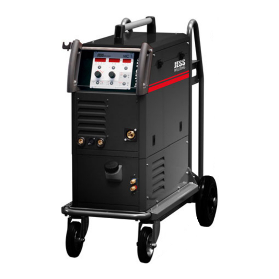
- Page 6 3 Produktbeschreibung inoMIG 350/400/500 3 Produktbeschreibung Technische Daten Abb. 1 inoMIG 350 compact und mit DVK3 Tab. 1 Technische Daten inoMIG 300/400 Stromquelle inoMIG 350 inoMIG 400 Netzspannung, 50/60 Hz 400 V, 3 Phasen (350 V – 480 V) 400 V, 3 Phasen Stromaufnahme Imax.
- Page 7 350/400/500 3 Produktbeschreibung Tab. 2 Technische Daten Drahtvorschub Drahtvorschub Kompakt/DVK3 Drahtvorschubmotor 42 V, 110 W Fördergeschwindigkeit 0,8–24 m/min Drahtdurchmesser 0,8–1,6 mm Gewicht DVK3 (solo) 20 kg Maße DVK3 L × B × H (mm) 580 × 270 × 560 Herstellung gemäß...
- Page 8 - int gemessener Temperaturwert' Erst wenn die Temperatur im vorgeschriebenen Bereich liegt, kann der Schweißvorgang gestartet werden. Typenschild Die Schweißstromquelle ist am Gehäuse mit einem Typenschild wie folgt gekennzeichnet: Abb. 3 Typenschild inoMIG 350 DE - 8 BA-0014 • 2020-10-15...
- Page 9 350/400/500 3 Produktbeschreibung Abb. 4 Typenschild inoMIG 400 Abb. 5 Typenschild inoMIG 500 Verwendete Zeichen und Symbole Beschreibung Symbol • Aufzählungssymbol für Handlungsanweisungen und Aufzählungen Querverweissymbol verweist auf detaillierte, ergänzende oder weiterführende Informationen Handlungsschritt/e im Text, die der Reihenfolge nach durchzuführen sind BA-0014 •...
- Page 10 4 Lieferumfang inoMIG 350/400/500 4 Lieferumfang • Schweißstromquelle • Betriebsanleitung • Beipackzettel „Allgemeine Sicherheitsinformationen“ Ausrüst- und Verschleißteile separat bestellen. Bestelldaten und Identnummern der Ausrüst- und Verschleißteile entnehmen Sie den aktuellen Bestellunterlagen. Kontakt für Beratung und Bestellung finden Sie im Internet unter www.jess-welding.com.
- Page 11 350/400/500 6 Funktionsbeschreibung 6 Funktionsbeschreibung Funktionsbeschreibung inoMIG 350 Abb. 6 Funktionsbeschreibung inoMIG 350 G Massebuchse Steuerbox MC1/MC2 Kühlgerät Buchse Elektrode Brenner Zentralanschluss Wasserrücklauf (rot), Anschluss up/down Brenner Wasservorlauf (blau) BA-0014 • 2020-10-15 DE - 11...
- Page 12 6 Funktionsbeschreibung inoMIG 350/400/500 Funktionsbeschreibung inoMIG 400 Abb. 7 Funktionsbeschreibung inoMIG 400 G Wasserrücklauf (rot), Steuerbox MC1/MC2 Steuerbox MC1/MC2 Massebuchse Anschluss up/down Brenner Brenner Zentralanschluss Wasservorlauf (blau) Hauptschalter (Rückseite) Wasserrücklauf (rot), Kühlgerät H Buchse Elektrode Brenner Zentralanschluss Wasservorlauf (blau) Anschluss up/down Brenner DE - 12 BA-0014 •...
- Page 13 350/400/500 6 Funktionsbeschreibung Funktionsbeschreibung inoMIG 500 Abb. 8 Funktionsbeschreibung inoMIG 500 Vorderseite G Primärsicherung Steuerbox MC1/MC2 Buchse Elektrode Brenner Zentralanschluss Anschluss up/down Brenner Kühlgerät H Kontrollleuchte Netz Wasserrücklauf (rot), Massebuchse Hauptschalter (Rückseite) Wasservorlauf (blau) BA-0014 • 2020-10-15 DE - 13...
- Page 14 6 Funktionsbeschreibung inoMIG 350/400/500 Abb. 9 Funktionsbeschreibung inoMIG 500 Rückseite Hauptschalter Buchse Gasausgang Netzkabel Datenleitung zum Drahtvorschubkoffer Gaseingang G Fernbedienbuchse 17-polig DE - 14 BA-0014 • 2020-10-15...
- Page 15 350/400/500 7 Inbetriebnahme 7 Inbetriebnahme GEFAHR Verletzungsgefahr durch unerwarteten Anlauf Für die gesamte Dauer von Wartungs-, Instandhaltungs-, Montage- bzw. Demontage- und Reparaturarbeiten ist Folgendes zu beachten: • Schalten Sie die Stromquelle aus. • Sperren Sie die Gaszufuhr ab. • Sperren Sie die Druckluftzufuhr ab.
- Page 16 7 Inbetriebnahme inoMIG 350/400/500 MIG/MAG-Schweißen 7.1.1 Schweißbrenner-Schlauchpaket anschließen Schutzgasflasche hinten auf die Schutzgasschweißanlage setzen und mit der Kette sichern. Flaschendruckminderer anschließen und Anschlüsse auf Dichtheit prüfen. Abb. 10 Schlauchpaket anschließen Anschluss Up-/Down-Brenner Brenner Zentralanschluss Wasserrücklauf „rot-heiß“ DN 5 Massebuchse Wasservorlauf „blau-kalt“ DN 5 Schweißbrenner wie im Bild dargestellt an Zentralanschluss, Wasseranschlüssen und wenn vorhanden...
- Page 17 350/400/500 7 Inbetriebnahme 7.2.2 Schweißvorgang starten Steuerbox auf die Betriebsart Elektrode stellen, Parameter für die Schweißaufgabe einstellen und Schweißvorgang durch Aufsetzen der Elektrode auf dem Schweißstück starten. 7.2.3 Hotstart und Arcforce einstellen Um einen besseren Start des Schweißvorganges zu erhalten, kann mit dem Parameter Hotstart (Tippen auf den Fx Knopf) ein erhöhter Startstrom eingestellt werden.
- Page 18 7 Inbetriebnahme inoMIG 350/400/500 7.3.2 WIG Schweißbrenner-Schlauchpaket Schweißbrenner wie im Bild dargestellt an Massebuchse, Fernbedienungsbuchse, Wasseranschlüsse und Gasausgang anschließen. Dabei die Farben der Wasseranschlüsse beachten. Drahtvorschubkoffer mit Steuerleitung muss an der Maschine eingesteckt bleiben. 7.3.3 Potentiometer Schweißstromregelung Um die Schweißstromstärke mit einem Potentiometer im WIG Betrieb regeln zu können, muss dieses wie im Schaltplan dargestellt an der 17-poligen Fernbedienungsbuchse angeschlossen werden.
- Page 19 350/400/500 8 Übersicht Steuerungsfunktionen 8 Übersicht Steuerungsfunktionen Tab. 5 Übersicht Steuerungsfunktionen MC1 und MC2 Funktionen Inverteranlage ■ ■ Handbetrieb ■ ■ Automatikbetrieb ■ ■ Lichtbogenlängenkorrektur ■ ■ Materialauswahl ■ ■ Leistung individuell einstellbar ■ ■ MIG Modus ■ ■...
- Page 20 9 Betrieb inoMIG 350/400/500 9 Betrieb HINWEIS • Jegliche Arbeiten am Gerät bzw. System sind ausschließlich befähigten Personen vorbehalten. Steuerungsfunktionen 9.1.1 Steuerung MC1 Abb. 14 Steuerbox MC1 Anzeige-Display G Auswahl Betriebsart M Bedientaste Schweißfunktionen Schweißspannung H LED-Anzeige Betriebsart N LED-Anzeige Einheiten Anzeige-Display Stromstärke...
- Page 21 350/400/500 9 Betrieb Pos. Beschreibung Drehknopf, um die Materialart einzustellen, die Lichtbogenlänge zu korrigieren (AUTO-(I)), die Drahtgeschwindigkeit in m/min (HAND-(I)) einzustellen bzw. um alle Werte im linken Display zu ändern Bedientaste Fx zum Einstellen der Schweißfunktionen (z.B. Drosselhärte antippen kürzer als 0,5 Sekunden) bzw.
- Page 22 10 Bedienung / Schweißen inoMIG 350/400/500 Pos. Beschreibung Bedientaste, um die Drahteinfädelfunktion zu aktivieren bzw. um im Einstellmodus die Werte von Drossel, Einschleichgeschwindigkeit, Drahtrückbrandzeit zu, Materialdicke und Leistung zu verkleinern (LED (C) blinkt) Bedientaste Mode, um zwischen den Betriebsarten MIG, Elektrode und WIG umzuschalten...
- Page 23 350/400/500 10 Bedienung / Schweißen Betriebsart Beschreibung 4-Takt Der Brennertaster wird gedrückt, und der Lichtbogen wird mit dem voreingestellten Hot-Start Strom (CSC) gezündet. Der Schweißstrom bleibt auf diesem Wert. Der Brennertaster wird losgelassen und der Strom fällt auf den eingestellten Schweißstrom mit der eingestellten Absenkgeschwindigkeit (SLO)
- Page 24 10 Bedienung / Schweißen inoMIG 350/400/500 Drossel (Cho) Stufenlose Korrektur der Schweißdrossel von +15 (Weicher) bis −15 (Härter) als „0“ (Standard) Punktzeit (SPt) 0,5 bis 10 Sekunden Code (CODE) Zum Sperren der Steuerung (siehe 10.15 auf Seite DE-25) HINWEIS *MC1 nur bei Kraterfüllen (LED S) aktiv 10.8 Betriebsart Elektrode...
- Page 25 350/400/500 10 Bedienung / Schweißen ► (D) wird immer zuerst der zuletzt geänderte Parameter Bei erneutem Drücken der Bedientaste angezeigt. Durch erneutes Tippen auf die Taste wird zum nächsten Parameter gewechselt. 10.15 Steuerung sperren – CODE (MC1) Die Steuerung für die Schweißaufgabe optimal einstellen. Um nun ein Verändern der Einstellungen durch Dritte zu verhindern, kann die Steuerung gesperrt werden.
- Page 26 10 Bedienung / Schweißen inoMIG 350/400/500 10.18 Kühlmittel – Durchflussanzeige (MC1) Um den aktuellen Durchfluss des Kühlmittels im Kühlkreislaufsystem anzuzeigen, muss die Bedientaste l/min lang gedrückt werden. Die LED l/min leuchtet auf, und im rechten Display wird der aktuelle Wert dargestellt (z.B.
- Page 27 350/400/500 11 Drahtvorschub DVK3 / DVK4 HINWEIS Es muss bei diesem Maschinentyp die Anzeige „CAn“ im rechten Display verwendet werden. Die Werte mit der Anzeige „int“ funktionieren bei diesem Maschinentyp nicht! z.B. EC1 - Choc - CAn Nun kann mit dem Poti 1 die Drossel verändert werden.
- Page 28 11 Drahtvorschub DVK3 / DVK4 inoMIG 350/400/500 11.2 DVK4 – 140 W Motor Abb. 18 Drahtvorschubmotor 140 W Drehgriff Drahtführungsrohr Drahtvorschubrolle oben Drahtvorschubrolle unten Inbusschraube Vierrollenantrieb Vier untereinander verzahnte Drahtvorschubrollen sorgen für einen sicheren Transport des Schweißdrahts. Für den verwendeten Draht muss jeweils die Drahtvorschubrolle mit der entsprechenden Nut eingesetzt werden.
- Page 29 350/400/500 12 Fernbedienungsdose 12 Fernbedienungsdose Tab. 6 Belegung Fernbedienungsdose Bezeichnung Beschreibung U-Ist Ausgangssignal zwischen 0 V und +10 V. Hier wird im Verhältnis 10:1 die aktuelle Schweißspannung für Steuerungszwecke ausgegeben. Beispiel: 40 V Schweißspannung = 4,0 V Signalspannung Eingangsimpedanz muss ≥10k Ω. Das Bezugspotential ist Pin 3.
- Page 30 13 Schweißbrenner mit Display inoMIG 350/400/500 13 Schweißbrenner mit Display HINWEIS Brenner nur bei ausgeschalteter Maschine wechseln. 13.1 Funktionen (nach Steuerbox sortiert) Tab. 7 Funktionen nach Steuerbox ■ ■ ■* ■ ■ ■ ■ ■ ■ ■ ■ ■ ■...
- Page 31 350/400/500 14 Funktionen mit erweiterter Auswahl 14 Funktionen mit erweiterter Auswahl 14.1 Funktion MODE (Mod) Mode 2-Takt / 4-Takt / Punkten - Krater: Mit der − Taste wird zwischen 2-Takt (2) und 4-Takt (4) gewechselt. (Anzeige linkes Display 2 oder 4) Mit der + Taste wird zwischen Normalbetrieb (−), Punkten (S) oder Krater (C) gewechselt.
- Page 32 15 Schweißbrennerkühlung / Kühlmittel inoMIG 350/400/500 15 Schweißbrennerkühlung / Kühlmittel HINWEIS Maximaler Betriebsdruck: 3,2bar Funktionsweise Die Schweißbrennerkühlung basiert auf der Funktion einer Rückkühlanlage, d.h. die Kühlflüssigkeit wird durch einen Wärmetauscher auf annähernd Raumtemperatur zurückgekühlt, mit Hilfe der vom Ventilator umgewälzten Raumluft.
- Page 33 350/400/500 17 Störungen und deren Beseitigung 17 Störungen und deren Beseitigung GEFAHR Verletzungsgefahr und Geräteschäden durch unautorisierte Personen Unsachgemäße Reparaturen und Änderungen am Produkt können zu erheblichen Verletzungen und Geräteschäden führen. Die Produktgarantie erlischt bei Eingriff durch unautorisierte Personen.
- Page 34 18 Fehlertabelle ERROR CODES inoMIG 350/400/500 Tab. 9 Störungen und deren Behebung Störung Ursache Behebung Poröse Schweißnaht Unsaubere Werkstückoberfläche (Farbe, Oberfläche reinigen Rost, Öl, Fett) Kein Schutzgas (Magnetventil öffnet nicht) Magnetventil prüfen / wechseln, Gasflasche prüfen Zu wenig Schutzgas Schutzgasmenge am Druckminderer prüfen Gasführung auf Gasverlust prüfen mit...
- Page 35 350/400/500 19 Materialtabelle 19 Materialtabelle Folgende Materialien sind standardmäßig in der Steuerung programmiert: Tab. 12 Materialtabelle Material Display MC Display MC Durchmesser mm Stahl* Argon 82 %, CO 18 % – MIX 18 Ar82 0,8–1,0–1,2–1,6 Stahl* Argon 90 %, CO...
- Page 36 20 Ersatzteilliste inoMIG 350/400/500 20 Ersatzteilliste 20.1 Ersatzteilliste inoMIG 300/400 Abb. 19 inoMIG 300/400 Frontansicht DE - 36 BA-0014 • 2020-10-15...
- Page 37 Steuerbox MC2 851.044.002 Feinsicherung T 6,3 A Steuerplatine 464.036.010 Drehknopf 28 mm 305.042.010 Deckel für Knopf 305.042.010 Klappe rechts 715.032.072 Frontteil inoMIG 350/400 715.032.032 Isolierflansch ZA Buchse 455.042.011 Kunststoffriegel (Verschluss) 303.625.007 Seitenblech rechts KG10 715.032.555 Verschlusskupplung DN5-G1/4I 355.014.007 Schutzbügel vorne FG10 715.032.650...
- Page 38 20 Ersatzteilliste inoMIG 350/400/500 Abb. 20 inoMIG 300/400 Seitenansicht DE - 38 BA-0014 • 2020-10-15...
- Page 39 420.025.001 Gegenmutter Kabelvers. M25 × 1,5 420.025.002 Inverterblock inoMIG 350 600.032.010 Inverterblock inoMIG 400 600.032.025 Lüfter 12 V DC (3212 JH) – inoMIG 350 450.092.005 Lüfter 24 V DC – inoMIG 400 450.119.005 Flaschenhalter FG10 715.032.649 Flaschenhaltebügel links FG10 715.032.645 Einbaubuchse Fernbedienung 17-polig 410.017.099...
- Page 40 20 Ersatzteilliste inoMIG 350/400/500 20.2 Ersatzteilliste DVK3 Abb. 21 Ersatzteilliste DVK3 DE - 40 BA-0014 • 2020-10-15...
- Page 41 350/400/500 20 Ersatzteilliste Tab. 15 Ersatzteilliste DVK3 Pos. Bezeichnung Art.-Nr. Haube DVK3 – 2010 715.042.206 Seitenblech rechts DVK3 – 2010 715.042.207 Kunststoffgriff klein 305.044.002 Steuerbox MC1 851.044.001 Feinsicherung T 6,3 A Steuerplatine 464.036.010 Drehknopf 28 mm 305.042.010 Deckel für Knopf 305.042.011...
- Page 42 20 Ersatzteilliste inoMIG 350/400/500 20.3 Ersatzteilliste inoMIG 500 Abb. 22 inoMIG 500 Frontansicht DE - 42 BA-0014 • 2020-10-15...
- Page 43 350/400/500 20 Ersatzteilliste Tab. 16 Ersatzteilliste inoMIG 500 außen Pos. Bezeichnung Art.-Nr. Drehdorn DVK3 715.032.163 Drehdorn DVK4 715.044.342 Haube 715.032.160 Seitenblech rechts 715.032.166 Frontfolie inoMIG 500 304.032.305 Frontteil inoMIG 500 715.032.152 Seitenblech rechts KG10 715.032.555 Blindplatte KG10 715.032.510 Schutzbügel vorne FG10 715.032.650...
- Page 44 20 Ersatzteilliste inoMIG 350/400/500 Abb. 23 Seitenansicht inoMIG 500 DE - 44 BA-0014 • 2020-10-15...
- Page 45 350/400/500 20 Ersatzteilliste Tab. 17 Ersatzteilliste inoMIG 500 innen Pos. Bezeichnung Art.-Nr. Flaschenhaltebügel rts FG10 715.032.642 Einbaubuchse Fernbedienung 17-polig 410.017.099 Kabelstecker 17-polig 410.017.100 Schutzkappe 310.350.051 Gasschlauch 709.150.001 Axialventilator 130 mm; H = 38 mm 450.130.002 Rückenteil inoMIG 500 715.032.360 Pumpe mit Lüfterrad 400 V/50–60 Hz...
- Page 46 20 Ersatzteilliste inoMIG 350/400/500 20.4 Ersatzteilliste DVK4 Abb. 24 Ersatzteilliste DVK4 DE - 46 BA-0014 • 2020-10-15...
- Page 47 350/400/500 20 Ersatzteilliste Tab. 18 Ersatzteilliste DVK4 Pos. Bezeichnung Art.-Nr. Scharnier 40 × 40 mm 303.056.003 Scharnierblech DVK4 – 2010 715.013.211 Kunststoffgriff klein 305.044.002 Schraube Torx PT60 271.060.001 Steuerbox MC1 851.044.001 Feinsicherung T 6,3 A Steuerplatine 464.036.010 Drehknopf 28 mm 305.042.010...
- Page 48 20 Ersatzteilliste inoMIG 350/400/500 20.5 Ersatzteile DVK3-MC-R Abb. 25 Ersatzteilliste DVK3-MC-R DE - 48 BA-0014 • 2020-10-15...
- Page 49 350/400/500 20 Ersatzteilliste Tab. 19 Ersatzteilliste DVK3-MC-R Pos. Bezeichnung Art.-Nr. Haube DVK3 – 2010 715.042.206 Seitenblech rechts DVK3 – 2010 715.042.207 Drehknopf 21 mm (Option) 305.020.050 Deckel für Knopf (Option) 305.020.051 Frontplatte MC-R 715.011.061 Drehknopf 28 mm (Option) 305.042.010 Deckel für Knopf (Option)
- Page 50 21 Schaltpläne inoMIG 350/400/500 21 Schaltpläne 21.1 inoMIG 350/400 Abb. 26 Kompakt-Maschine DE - 50 BA-0014 • 2020-10-15...
- Page 51 350/400/500 21 Schaltpläne Abb. 27 Maschine mit Koffer BA-0014 • 2020-10-15 DE - 51...
- Page 52 21 Schaltpläne inoMIG 350/400/500 Abb. 28 Kompakt-Maschine mit Koffer DE - 52 BA-0014 • 2020-10-15...
- Page 53 350/400/500 21 Schaltpläne 21.2 inoMIG 500 Abb. 29 inoMIG 500 Standard BA-0014 • 2020-10-15 DE - 53...
- Page 54 21 Schaltpläne inoMIG 350/400/500 Abb. 30 inoMIG 500 mit MC-R – Platine im Koffer DE - 54 BA-0014 • 2020-10-15...
- Page 55 350/400/500 Notizen Notizen BA-0014 • 2020-10-15 DE - 55...
-
Page 56: Table Of Contents
DVK4 – 140 W motor EN-28 11.3 Wire guiding in the welding torch cable Functional description assembly EN-28 EN-11 inoMIG 350 functional description EN-11 inoMIG 400 functional description EN-12 Remote control socket EN-29 inoMIG 500 functional description EN-13 Welding torch with display... -
Page 57: Identification
350/400/500 1 Identification 1 Identification The inoMIG 350/400/500 MIG/MAG welding machines were developed for industrial applications. Their features and functions were therefore designed for professional use. Marking This product fulfils the requirements that apply to the market to which it has been introduced. -
Page 58: Classification Of The Warnings
2 Safety inoMIG 350/400/500 Classification of the warnings The warnings used in the operating instructions are divided into four different categories and are indicated prior to potentially dangerous work steps. Arranged in descending order of importance, they have the following meanings: DANGER Describes an imminent threatening danger. -
Page 59: Warning And Information Signs
350/400/500 2 Safety Warning and information signs The following warning and information signs can be found on the product: Symbol Meaning Read and observe the operating instructions! Disconnect the mains plug before opening! Warning against hot surfaces. Emergency information In the event of an emergency, immediately disconnect the following supplies: •... -
Page 60: Product Description
3 Product description inoMIG 350/400/500 3 Product description Technical data Fig. 1 inoMIG 350 compact and with DVK3 Tab. 1 inoMIG 300/400 technical data Power source inoMIG 350 inoMIG 400 Mains voltage 50/60 Hz 400 V, 3 phase (350–480 V) - Page 61 350/400/500 3 Product description Tab. 2 Wire feeder technical data Wire feeder Compact/DVK3 Wire feeder motor 42 V, 110 W Conveying speed 0.8–24 m/min Wire diameter 0.8–1.6 mm Weight DVK3 (solo) 20 kg Dimensions DVK3 L × W × H (mm) 580 ×...
-
Page 62: Ambient Conditions
“t°C - int gemessener Temperaturwert” (t°C - int. measured temperature value) The welding process cannot begin until the temperature is within the correct range. Nameplate The welding power source is labelled with a nameplate on the housing as follows: Fig. 3 inoMIG 350 nameplate EN - 8 BA-0014 • 2020-06-05... -
Page 63: Signs And Symbols Used
350/400/500 3 Product description Fig. 4 inoMIG 400 nameplate Fig. 5 inoMIG 500 nameplate Signs and symbols used Description Symbol • Bullet symbol for instructions and lists Cross reference symbol refers to detailed, supplementary or further information Step(s) described in the text to be carried out in succession BA-0014 •... -
Page 64: Scope Of Delivery
4 Scope of delivery inoMIG 350/400/500 4 Scope of delivery • Welding power source • Operating instructions • “General safety information” instruction leaflet Order the equipment parts and wear parts separately. The order data and ID numbers for the equipment parts and wear parts can be found in the current product catalogue. -
Page 65: Functional Description
350/400/500 6 Functional description 6 Functional description inoMIG 350 functional description Fig. 6 inoMIG 350 functional description G Ground socket MC1/MC2 control box Cooling unit Electrode socket Central connector for torch Water return (red), water flow (blue) Up/down torch connector BA-0014 •... -
Page 66: Inomig 400 Functional Description
6 Functional description inoMIG 350/400/500 inoMIG 400 functional description Fig. 7 inoMIG 400 functional description G Water return (red), MC1/MC2 control box MC 1/MC 2 control box Ground socket Up/down torch connector Central connector for torch water flow (blue) Main switch (rear) -
Page 67: Inomig 500 Functional Description
350/400/500 6 Functional description inoMIG 500 functional description Fig. 8 Functional description inoMIG 500 front G Primary fuse MC1/MC2 control box Electrode socket Main switch (rear) Up/down torch connector Cooling unit H Mains indicator light Central connector for torch... -
Page 68: Putting Into Operation
7 Putting into operation inoMIG 350/400/500 Fig. 9 Functional description inoMIG 500 rear Main switch Socket Gas outlet Mains cable Data cable to wire feed unit Gas inlet G 17-pole remote control socket 7 Putting into operation DANGER Risk of injury due to unexpected start... -
Page 69: Mig/Mag Welding
350/400/500 7 Putting into operation CAUTION Risk of injury Heavy weight. • Ensure that you slow down in good time when moving the device. NOTICE • Note the following instructions: 3 Product description on page EN-6 • Only qualified personnel are permitted to perform work on the device or system. -
Page 70: Electrode Welding
7 Putting into operation inoMIG 350/400/500 Electrode welding Fig. 11 Connecting the electrode holder Ground socket Electrode socket/TIG Connect the electrode holder to the Plus socket as illustrated. Please always observe the specifications of the electrode manufacturer in relation to polarity! The wire feed unit with control lead must remain plugged into the machine. -
Page 71: Tig Welding
350/400/500 7 Putting into operation TIG welding Fig. 12 Connect the TIG welding torch/hose torch Ground socket 17-pole remote control socket Electrode socket G Data cable to wire feed unit H + socket Start Water return “red-hot” Gas outlet Water flow “blue-cold”... -
Page 72: Downslope And Gas Post-Flow Time Parameters
7 Putting into operation inoMIG 350/400/500 7.3.5 Downslope and gas post-flow time parameters You can use the downslope parameter (tap on the Fx button) to set the length of time it takes the welding current to drop to the minimum current of 15 A after the end of welding. The gas post-flow time is the length of time during which the gas continues to flow to cool the torch after the end of welding. -
Page 73: Overview Of Control Functions
350/400/500 8 Overview of control functions 8 Overview of control functions Tab. 5 Overview of MC1 and MC2 control functions Functions Inverter system ■ ■ Manual mode ■ ■ Automatic mode ■ ■ Arc length correction ■ ■ Material selection ■... -
Page 74: Operation
9 Operation inoMIG 350/400/500 9 Operation NOTICE • Only qualified personnel are permitted to perform work on the device or system. Control functions 9.1.1 MC1 control system Fig. 14 MC1 control box Welding voltage display G Select operating mode M Welding functions operating... -
Page 75: Mc2 Control System
350/400/500 9 Operation Pos. Description Fx operating button for setting welding functions (e.g. for throttle strength, tap for less than 0.5 seconds) or options (e.g., for remote control, press for more than 1 second) LED indicator for the units % or seconds if these values are shown in the middle display... -
Page 76: Operation/Welding
10 Operation/welding inoMIG 350/400/500 Pos. Description Knob for adjusting the welding power in the middle display Knob for setting the material type, adjusting the arc length (AUTO-(I)), setting the wire speed in m/min (HAND-(I)), and changing all values in the left-hand display... -
Page 77: Automatic/Manual Mode (Mc1-2
350/400/500 10 Operation/welding 10.3 Automatic/manual mode (MC1–2) Press and hold the material button (for more than 1 second) to switch between automatic and manual mode. In automatic mode, all parameters required for welding are set and maintained automatically by the control system. -
Page 78: Tig Operating Mode
10 Operation/welding inoMIG 350/400/500 10.9 TIG operating mode Gas post-flow time (PoG) 2 to 20 seconds Down slope (i.e. reduce current) 0.0 to 10.0 seconds (dSLP) Use the middle knob to adjust the values within their ranges. If the value is not changed for more than 2 seconds, the display switches to default and saves the value. -
Page 79: Fx Options (Mc1
350/400/500 10 Operation/welding 10.16 Fx options (MC1) This function can be used to change the lower-level basic settings. Press and hold the Fx operating button (for more than 1 second) to access the options. The following options can be changed: •... -
Page 80: Mig, Electrode, Tig Operating Modes (Mc1-2
10 Operation/welding inoMIG 350/400/500 NOTICE After the reset “ALL”, all parameters must be checked to ensure they are correctly set for the machine type. 10.20 MIG, electrode, TIG operating modes (MC1–2) Tap the operating button to switch between MIG, electrode and TIG operating modes. The relevant LED illuminates. -
Page 81: Wire Feeder Dvk3/Dvk4
350/400/500 11 Wire feeder DVK3/DVK4 11 Wire feeder DVK3/DVK4 11.1 DVK3 – 100 W motor Fig. 17 100 W wire feed motor Spring-pressure unit Allen screw Wire guide tube Wire-holding arbor Knurled screw G Wire spool Wire feed roller Replacing the wire feed roller (D). -
Page 82: Dvk4 - 140 W Motor
11 Wire feeder DVK3/DVK4 inoMIG 350/400/500 11.2 DVK4 – 140 W motor Fig. 18 140 W wire feed motor Twist handle Wire guide tube Wire feed roller top Wire feed roller bottom Allen screw 4-roller drive Four interlocking wire feed rollers ensure that the welding wire is conveyed securely. The correct wire feed roller with the corresponding groove must be inserted for the wire used in each case. -
Page 83: Remote Control Socket
350/400/500 12 Remote control socket 12 Remote control socket Tab. 6 Remote control socket pin assignment Name Description U-actual Output signal between 0 V and +10 V. The current welding voltage is output here in the ratio 10:1 for control purposes. -
Page 84: Welding Torch With Display
13 Welding torch with display inoMIG 350/400/500 13 Welding torch with display NOTICE Only replace the torch when the machine is switched off. 13.1 Functions (sorted by control box) Tab. 7 Functions sorted by control box ■ ■ ■* ■... -
Page 85: Functions With Extended Selection
350/400/500 14 Functions with extended selection 14 Functions with extended selection 14.1 MODE function (Mod) 2-Step/4-step/spot – crater mode: Use the “−” button to switch between 2-step (2) and 4-step (4) mode. (Left-hand display shows 2 or 4) Use the “+” button to switch between normal operation ( − ), spot (S) or crater (C) welding. (Right-hand display shows −... -
Page 86: Welding Torch Cooling/Coolant
15 Welding torch cooling/coolant inoMIG 350/400/500 15 Welding torch cooling/coolant NOTICE Max. operating pressure: 3.2 bar Procedure Welding torch cooling is based on the function of a recooling system, i.e., the coolant is cooled down to a temperature close to room temperature by a heat exchanger, using the room air circulated by the fan. - Page 87 350/400/500 17 Troubleshooting Tab. 9 Troubleshooting Fault Cause Troubleshooting Display shows T°C - 01/02/03 - hot Machine is overheating Allow the machine to cool down with the fan running Thermal sensor cable interrupted Find and eliminate the interruption Incorrect machine type set in the control Contact the service partner Display shows T°C - int - e.g.
-
Page 88: Table Of Error Codes And Errors
18 Table of ERROR CODES and errors inoMIG 350/400/500 Tab. 9 Troubleshooting Fault Cause Troubleshooting Porous weld seam Surface of workpiece is soiled (dye, rust, Clean the surface oil, grease) No shielding gas (solenoid valve does not Check/replace the solenoid valve, check... -
Page 89: Material Table
350/400/500 19 Material table 19 Material table The following materials are programmed in the control system by default: Tab. 12 Material table Material Display MC Display MC Diameter (mm) Steel* Argon 82%, CO 18% – MIX 18 Ar82 0.8–1.0–1.2–1.6... -
Page 90: Spare Parts List
20 Spare parts list inoMIG 350/400/500 20 Spare parts list 20.1 Spare parts list for the inoMIG 300/400 Fig. 19 Front view of inoMIG 300/400 EN - 36 BA-0014 • 2020-06-05... - Page 91 Fine-wire fuse T 6,3 A control board 464.036.010 Knob 28 mm 305.042.010 Cover for knob 305.042.010 Right flap 715.032.072 Front section inoMIG 350/400 715.032.032 Insulating flange for central connection socket 455.042.011 Plastic lock (seal) 303.625.007 Right side panel KG10 715.032.555 Quick-action coupling DN5-G1/4I 355.014.007...
- Page 92 20 Spare parts list inoMIG 350/400/500 Fig. 20 inoMIG 300/400 Side view EN - 38 BA-0014 • 2020-06-05...
- Page 93 Counternut cable connection M25 × 1.5 420.025.002 Inverter block inoMIG 350 600.032.010 Inverter block inoMIG 400 600.032.025 Fan 12 V DC (3212 JH) – inoMIG 350 450.092.005 Fan 24 V DC – inoMIG 400 450.119.005 Bottle holder FG10 715.032.649 Retaining bracket for bottle, left FG10 715.032.645...
-
Page 94: Spare Parts List For Dvk3
20 Spare parts list inoMIG 350/400/500 20.2 Spare parts list for DVK3 Fig. 21 Spare parts list for DVK3 EN - 40 BA-0014 • 2020-06-05... - Page 95 350/400/500 20 Spare parts list Tab. 15 Spare parts list for DVK3 Pos. Name Item no. Hood DVK3 – 2010 715.042.206 Right side panel DVK3 – 2010 715.042.207 Plastic handle, small 305.044.002 MC1 control box 851.044.001 Fine-wire fuse T 6,3 A control board 464.036.010...
-
Page 96: Spare Parts List For The Inomig
20 Spare parts list inoMIG 350/400/500 20.3 Spare parts list for the inoMIG 500 Fig. 22 Front view of inoMIG 500 EN - 42 BA-0014 • 2020-06-05... - Page 97 350/400/500 20 Spare parts list Tab. 16 External spare parts list for inoMIG 500 Pos. Name Item no. Turning mandrel DVK3 715.032.163 Turning mandrel DVK4 715.044.342 Hood 715.032.160 Right side panel 715.032.166 Front foil inoMIG 500 304.032.305 Front section inoMIG 500 715.032.152...
- Page 98 20 Spare parts list inoMIG 350/400/500 Fig. 23 Side view of inoMIG 500 EN - 44 BA-0014 • 2020-06-05...
- Page 99 350/400/500 20 Spare parts list Tab. 17 Internal spare parts list for inoMIG 500 Pos. Name Item no. Retaining bracket for bottle, right FG10 715.032.642 17-pole panel socket for remote control 410.017.099 17-pole cable plug 410.017.100 Protective cap 310.350.051 Gas hose 709.150.001...
-
Page 100: Spare Parts List For Dvk4
20 Spare parts list inoMIG 350/400/500 20.4 Spare parts list for DVK4 Fig. 24 Spare parts list for DVK4 EN - 46 BA-0014 • 2020-06-05... - Page 101 350/400/500 20 Spare parts list Tab. 18 Spare parts list for DVK4 Pos. Name Item no. Hinge 40 × 40 mm 303.056.003 Hinge plate DVK4 – 2010 715.013.211 Plastic handle, small 305.044.002 Torx screw PT60 271.060.001 MC1 control box 851.044.001...
-
Page 102: Spare Parts List For Dvk3-Mc-Ren-48
20 Spare parts list inoMIG 350/400/500 20.5 Spare parts list for DVK3-MC-R Fig. 25 Spare parts list for DVK3-MC-R EN - 48 BA-0014 • 2020-06-05... - Page 103 350/400/500 20 Spare parts list Tab. 19 Spare parts list for DVK3-MC-R Pos. Name Item no. Hood DVK3 – 2010 715.042.206 Right side panel DVK3 – 2010 715.042.207 Knob 21 mm (optional) 305.020.050 Cover for knob (optional) 305.020.051 Front panel MC-R 715.011.061...
-
Page 104: Circuit Diagrams
21 Circuit diagrams inoMIG 350/400/500 21 Circuit diagrams 21.1 inoMIG 350/400 Fig. 26 Compact machine EN - 50 BA-0014 • 2020-06-05... - Page 105 350/400/500 21 Circuit diagrams Fig. 27 Machine with case BA-0014 • 2020-06-05 EN - 51...
- Page 106 21 Circuit diagrams inoMIG 350/400/500 Fig. 28 Compact machine with case EN - 52 BA-0014 • 2020-06-05...
-
Page 107: Inomig
350/400/500 21 Circuit diagrams 21.2 inoMIG 500 Fig. 29 inoMIG 500 standard BA-0014 • 2020-06-05 EN - 53... - Page 108 21 Circuit diagrams inoMIG 350/400/500 Fig. 30 inoMIG 500 with MC-R – PCB in case EN - 54 BA-0014 • 2020-06-05...
- Page 109 350/400/500 Notes Notes BA-0014 • 2020-06-05 EN - 55...
- Page 110 Notes inoMIG 350/400/500 Notes EN - 56 BA-0014 • 2020-06-05...
- Page 111 350/400/500 Notes Notes BA-0014 • 2020-06-05 EN - 57...
- Page 112 J ä c k l e & E s s S y s t e m G m b H Jäckle & Ess System GmbH Riedweg 4 u. 9 • D–88339 Bad Waldsee Tel.: ++49 (0) 7524 9700–0 Fax: ++49 (0) 7524 9700–30 Email: sales@jess-welding.com www.jess-welding.com...
Need help?
Do you have a question about the inoMIG 350 and is the answer not in the manual?
Questions and answers