Table of Contents
Advertisement
Quick Links
Advertisement
Table of Contents

Related Manuals for JESS WELDING Power Plasma 2


Summary of Contents for JESS WELDING Power Plasma 2
- Page 1 Operating manual Power Plasma 2...
- Page 2 General information’s: These operating instructions are intended to ensure safe and efficient work with this cutting unit. Prior to initial operation of the unit, read the instructions carefully. The information contained in this manual should be made available to all operational staff.
- Page 3 Power Plasma 2...
-
Page 4: Table Of Contents
Power Plasma 2 Contents Page Some general information about plasma cutting ............1 Safety Requirements ....................2 Brief description ......................5 Technical Data ......................6 Control Elements ......................7 Initial operation ......................8 Preparations for cutting ....................10 Cutting ........................11 Water flow Control / trouble .................. -
Page 5: Some General Information About Plasma Cutting
Power Plasma 2 1. Some general information about plasma cutting 1.1 Operating principle In a plasma torch, the air is heated to an extremely high temperature through an electric arc, thus forming an electroconductive plasma which allows the cutting current to flow from the electrode to the workpiece. -
Page 6: Safety Requirements
Power Plasma 2 2. Safety Requirements 2.1 General Information’s This welding unit has been manufactured in accordance with the relevant interna- tional standards. However, improper use or manipulation of the machine may cause hazards. The following safety instructions must be strictly observed: a) This unit is exclusively intended for the Plasma cutting process. - Page 7 Power Plasma 2 2.3 Personal Protection The face and the eyes must be protected by a welder´s shield with lenses - protection category corresponding to the intensity of current. Persons working close by must also be adequately protected from arc radiation.
- Page 8 Power Plasma 2 EMC and safety inspection Apart from the instructions given in this operating manual, the general safety standards, in particular the rules for prevention of accidents must be observed. The rules contain additional information’s about the prevention of radiation, smoke, combustion, electric shock, fire and explosion.
-
Page 9: Brief Description
Power Plasma 2 3. Brief description The Plasma Cutting Unit Power Plasma 2 has been developed in robust technology. It excels in multipurpose application both for manual cutting operations and in combina- tion with automatic or robot-operated cutting processes. Its Operating principle is characterised by the following: Compressed air as plasma gas for the plasma torch A high-grade filter welding regulator is standard equipment on this unit. -
Page 10: Technical Data
Power Plasma 2 4. Technical Data Supply voltage 3-phase 400 V, 50 Hz Max. power draw 45 kVA Fuse 63 A slow Set-point range infinitely variable 20 - 210 A Max. open-circuit voltage 345 V 100 % duty cycle 210 A/164 V Max. -
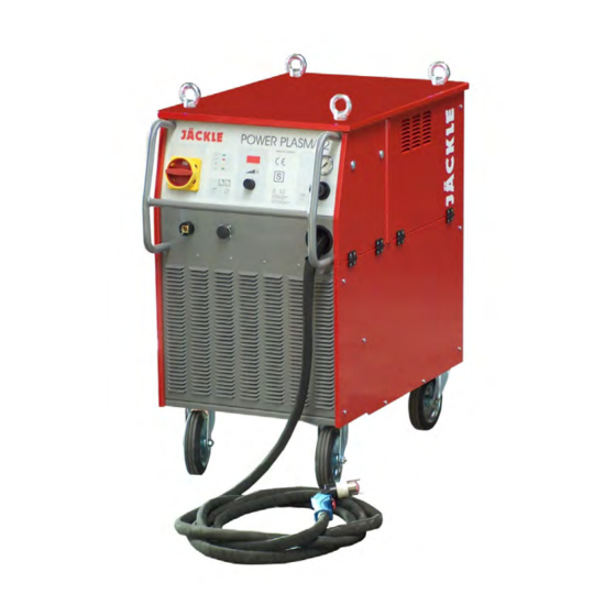
Page 11: Control Elements
Power Plasma 2 5. Control Elements 2 3 4 5 POWER PLASMA 2 MADE IN GERMANY W a r n u n g: U > 100 V Bei Brenner-Wechsel oder -Wartung Betriebsanleitung beachten! W a r n i n g: U > 100 V... -
Page 12: Initial Operation
Power Plasma 2 Compressed air gauge shows the air pressure after the filter pressure reducer Digital display of welding current The actual welding current value is continuously displayed during the welding operation. Rotary type Control knob for infinitely variable regulation of cutting current Regulates the cutting current between 20 A and 210 A. - Page 13 Power Plasma 2 6.5 Connections for plasma torch or Plasmaignitionbox • Open the flap in the right side panel by turning the knob left. • Put the torch connections through the opening in the front into the connection box inside. Connect the cables with the isolated screw fittings G 3/8 and M6. The connections must be fixed.
-
Page 14: Preparations For Cutting
Power Plasma 2 7. Preparations for cutting 7.1 Regulation of cutting current Set the cutting current dependant to the material and thickness of the workpiece. In manual cutting operations, the current setting should be high enough to enable continu- ous manipulation of the cutting torch. -
Page 15: Cutting
Power Plasma 2 8. Cutting 8.1 Pilot arc ignition Bring the nozzle of the cutting torch to the starting point of the cut to be executed. Press torch trigger. After a short preweld gas flow time the pilot arc is ignited, and at the instant of the pilot arc impacting the workpiece, the cutting arc is formed. -
Page 16: Water Flow Control / Trouble
Power Plasma 2 9. Water flow Control / trouble The machine has a water flow meter in the cooling circuit. If the water pump is running, the water quantity (litre / minute) is shown in the display by pressing the Compressed-air test key (Chap. 5-6). -
Page 17: Remote Control Socket
Power Plasma 2 11. Remote Control socket If the led on the front panel is light, the following functions are possible (chap. 5-11) (see also circuit diagram chap.15): Pin A: Arc voltage; 10V Arc voltage ≙ 0,2V signal voltage Pin B: Cutting current; 5A cutting current ≙ 0,2V signal voltage Pin C: Ground (GND) for Pin A and B Pin D: Begin external Poti ‘cutting current’;... -
Page 18: Trouble-Shooting
Power Plasma 2 13. Trouble-Shooting Malfunction/error Cause Remedy mains connected and mains fuse has been Check mains fuse; if required, master switch in pos.“I“ tripped increase fuse protection, /‘mains’ Control lamp is mains cable interruption Check mains cable not lit... - Page 19 Power Plasma 2 Malfunction/error Cause Remedy Error code ‚PIL’ Pilot resistor overheated Wait until the resistor has cooled down. Check if the machine is switching correct from pilot arc to cutting arc. Error code ‚H20’ Low-water alarm Check water in tank and the water connections (Chap.
-
Page 20: Spare Parts
Power Plasma 2 14. Spare Parts Picture 14.1 Frontview Operating Manual Page 16... - Page 21 Power Plasma 2 Pos. Description Number Ring nut M12 C15 D582 M12V Case 715.023.125 Frontfilm 304.023.100 Main switch H406-41300-033N4 440.233.003 Rotation Control knob D28mm black 305.042.010 Cover D28mm black 305.042.011 Work piece socket BEB 35-50 422.031.024 Remote Control socket 410.010.044 Protective cap 310.350.050...
-
Page 22: Picture 14.2 Sideview
Power Plasma 2 Pic. 14.4 Picture 14.2 Sideview Operating Manual Page 18... - Page 23 Power Plasma 2 Pos. Description Number Fuse holder with bayonet type sealing cap 464.601.001 Fine-wire fuse 5x20 mm 3,15A slow 464.031.015 Rotary switch 4x3 440.034.109 Flap security switch XP52 441.001.001 HF - Ignition SIG 3.2 24V 438.032.002 438.016.005 HF - filter DGF 3 HF blocking choke 1R100-25-14 438.100.019...
-
Page 24: Picture 14.3 Inside
Power Plasma 2 Picture 14.3 Inside Pos. Description Number Choke Type PLD 1 438.001.003 HF protection PCB P1-H 600.021.001 Control transformer power 2 462.023.001 Small Contactor DL 4K-10 24V/50Hz (Pilot) 442.024.011 Big Contactor (Main) 442.024.018 Fuse holder with bayonet type sealing cap 464.601.001... -
Page 25: Picture 14.4 Air Unit
Power Plasma 2 Picture 14.4 Air unit Pos. Description Number Solenoid valve unit Power 2 complete (Pos. 90 -101) 703.023.150 Manometric switch 1 - 10 bar, M 10x1 444.001.001 Socket with ball nipple G1/4-6 354.146.049 Swivel nut for socket 354.146.051 Dual nipple for Pressure reducing nozzle 357.144.015... -
Page 26: Circuit Diagrams
Power Plasma 2 15. Circuit diagrams Power 2 Plasmaunit brown black blue blue brown black blue blue brown black black 400 V 24 V 230 V 3,15 AT 3,15 AT Flatcable 20polig LCH1CNT SPDR Thermo- LCH1DRV switch U-Ist Transformer P1-H... - Page 27 Power Plasma 2 Intermediate hose pack Plasmabox socket inside flap Manual- Torch trigger or torch Safetyswitch Machine- torch Torch Plasmaignitionbox (Option) T 2 A Torch Driving PCB LCH1DRV Control PCB LCH1CNT PCB INV 2x PIO Manual- INV2xPIO torch PCB PL - Cont1...
Need help?
Do you have a question about the Power Plasma 2 and is the answer not in the manual?
Questions and answers