Table of Contents
Advertisement
Quick Links
pmvmounts
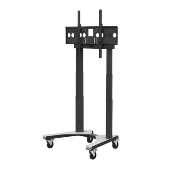
Assembly instructions for dual screen kits PMVTROLLEYXLDS1
& PMVTROLLEYXLDS2 on to PMVTROLLEYXL or PMVSTAND.
PMVTROLLEYXLDS1 - x2 40" - 55" up to 30Kg per screen.
- x2 27" - 46" up to 30Kg per screen in landscape.
PMVTROLLEYXLDS2
- x2 47" - 55" up to 30Kg per screen in portrait
Component checklist
900mm aluminium extrusion assembled with joining plate x2 (PMVTROLLEYXLDS1)
600mm extrusion with joining plate x2 (PMVTROLLEYXLDS2)
600mm trim inserts x3 (DS1) x2 (DS1)
Vertical TV mounting arms x4
Horizontal TV mounting arms x4
Support brace x1
Tilting VESA plate x2
Assembly fixing kit checklist
X40
A - M8 washer
X28
B - M8 x 12mm
C - M8 nut cover
D - M8 x 16mm
X12
E - M8 nut
.co.uk
Extrusion trim pieces x2
Top supports x2
Open sliders x4
Screen mount hanger x2
TV mounting plate
sliders x4
Single stud
slider x4
Screen fixing kit checklist
F - M4 x 20mm
G - M5 x 20mm
H - M6 x 20mm
I - M8 x 20mm
J - M5 washer
X4
K - M6 washer
L - M8 washer
X3
M - M4 x 5mm
N - M5 x 5mm
O - M6 x 6mm
P - M6 x 6mm
Read these instructions carefully before assembling this equipment.
Assemble in a suitable location.
Check the equipment has been supplied with all parts and fixtures prior to assembly.
Three people will be required for assembly and for installation of the screens on to the equipment.
Do not attempt to alter or modify any part of the equipment or its attachments.
Do not use if any parts are broken or appear to be damaged.
Only use fixings provided with this bracket.
Tighten all bolts and fixings securely with appropriately sized tools.
Do not position the equipment close to sources of heat or moisture.
NOTE:
PMVTROLLEYXLDS1 & PMVTROLLEYXLDS2 are not standalone products, they
should knowingly be sold and used as an accessory(s) for PMVTROLLEYXL or
PMVSTAND only.
PMVTROLLEYXL should be built in full prior to installation of the TV bracket as per
its instructions. The x4 lower trim inserts can be installed but it may be beneficial to
install the x2 upper trim inserts after the trolley and dual screen accessory are fully
installed and cabling can be tidied.
PMVSTAND should be built in full as per its included instructions. The x4 lower trim
inserts can be installed but it may be beneficial to install the x2 upper trim inserts
after the trolley and dual screen accessory are fully installed and cabling can be
tidied.
If your trolley or stand are assembled with castors, ensure the brakes are applied until
installation of screens and they are bolted in to their final position.
PMVTROLLEYXL
Trim Inserts:
You may find it easier to insert one of each 600mm trim inserts in to each of the
extrusions before installing the dual screen kit on to the trolley.
For PMVTROLLEYXLDS1 you will need to cut your third trim insert at its mid length
with sharp scissors or a safety knife or as your needs require.
Inserts can be installed by sliding them down the formed grooves of the extrusion or
placed in one groove and popped in to the opposing groove.
The trim pieces can be cut with a safety knife after installation to make small entry
and exit points for cables.
Trim inserts are made from a plastic board material and like any paper or cardboard
product can be sharp. Do not pull or tug your cables against edges of the board as
this may damage the protective sheath of the cable.
Top down view
X8
management
X8
X8
PMVSTAND
Outside face of extrusion
Slider gully
Inside face of extrusion
Cable
Trim insert
gully
Designed & Manufactured
in the United Kingdom
Isometric
view
Trim insert
Advertisement
Table of Contents

Related Manuals for pmvmounts PMVTROLLEYXLDS1


Summary of Contents for pmvmounts PMVTROLLEYXLDS1
- Page 1 For PMVTROLLEYXLDS1 you will need to cut your third trim insert at its mid length with sharp scissors or a safety knife or as your needs require.
- Page 2 Component assembly 1A - Assemble together the extrusion support brace with two open ‘sliders’ using x4 (A) M8 washers and x4 (B) M8x12mm button head bolts - Fig 1A 1B - Assemble together the x2 extrusion top supports with x2 open ‘sliders’ each using x2 (A) M8 washers and x2 (B) M8x12mm button head bolts - Fig 1B 1C - Ensure there is a 5mm gap between the brace / support bracket and the sliders to allow easy fitment to the trolley or stand - Fig 1C Not to scale...
- Page 3 Assemble extrusions together Position horizontal extrusion on to trolley / stand. Note - Lay extrusions on a soft surface so as not to mark the paint finish, 4A - Two persons should lift the horizontal extrusion up and over with assistance you can assemble the extrusions whilst they’re upright. the support brace installed at Step 2.
- Page 4 Assemble screen mounts with sliders 6A - Assemble x2 ‘TV mounting plate sliders’ on the inside of a TV mounting plate using x4 M8 x 12mm button head bolts - Fig 6A 6B - Leave a 5mm gap between the slider and the mounting plate - Fig 6b 6C - Repeat above steps so you have two matching assembled mounting plates ready to install.
- Page 5 Attach mounting frame to TV / display / screen. Note: For screens with a VESA pattern of 200x200 or less proceed to step 8A. Note: For screens with VESA patterns over 200x200 proceed to step 8C. 8A - Attach TV tilt plate directly to back of screen for screens with VESA 75, 100 and 200, use fixings suitable to your screen from universal TV fixing kit - Fig 8A F-Ix4 8B - If the screen is uneven, has raised moulded areas or you need clearance for cables...
- Page 6 Mount screens to trolley / stand. Three persons are required for this step. Note - Two persons should lift each screen in to position whilst a third person supports the trolley until both screens are in position and secured. 9A - Hook the TV tilt plate over the corresponding mounts on the sliding mount on the trolley- Fig 9A 9B - Insert x2 (A) M8 washers and x2 (B) M8x12mm to secure the TV tilt plate on to the sliding mount, tighten when screen is at the desired tilt angle - Fig 9B 9C - Repeat above steps to install and secure the second screen.
Need help?
Do you have a question about the PMVTROLLEYXLDS1 and is the answer not in the manual?
Questions and answers