
Related Manuals for Liftsafe Fall Protection RoofGuard RGC-RA

Summary of Contents for Liftsafe Fall Protection RoofGuard RGC-RA
- Page 1 User Instruction Guide for RoofGuard Kits: RGC-RA HG-KIT-08 RGC-KIT-09 RGC-KIT-18V RGC-KIT-27V Liftsafe Fall Protection Inc. RoofGuard Classic Kit Instruction Manual RGC-KM-3.3...
-
Page 2: Table Of Contents
TABLE OF CONTENTS Section Page # 1.0 Application 2.0 RGC-RA System Requirements 3.0 RGC-Restraint Anchor 4.0 Rooftop Guardrail System Requirements 5.0 System Layout 6.0 Installation HG-KIT-08 7.0 Installation RGC-KIT-09 8.0 Installation RGC-KIT-18V 9.0 Installation RGC-KIT-27V 10.0 Detailed Inspection and Maintenance Log 11.0 Warranty 12.0 Appendix... - Page 3 WARNINGS AND CONDITIONS This system is part of a personal fall protection system. The user must read and follow all guidelines in this manual. These instructions must be provided to the user of this system. The user must read and understand these instructions or have them explained to them prior to using the system.
-
Page 4: Section 1.0 Application
1.0 APPLICATION 1.1 The RoofGuard Kit systems are designed to be installed on a flat roof (up to 5% grade) to provide protection for workers near the edge or an exposed opening in the roof. Depending on the roof surface, a rubber pad or ultra-light paving stone may be used under the baseplates to facilitate safe/stable contact with the roof surface. -
Page 5: Rgc-Ra System Requirements
2.0 RGC-RA SYSTEM REQUIREMENTS 2.1 The RoofGuard Restraint Anchor System is designed to be used on flat roofs (up to 5% grade) where the baseplates can sit flat on the roof surface. Depending on the roof surface, a rubber pad, or ultra-light paving stone may be used under the baseplates to facilitate safe/stable contact with the roof surface. -
Page 6: Rgc-Restraint Anchor
3.0 INSTALLATION RGC- RESTRAINT ANCHOR 3.1 COMPONENTS 3.1-A The RoofGuard Restraint Anchor system consists of the Anchor Kit and 12 of the standard RoofGuard System Baseplates. The Anchor Kit contains: 2 pcs of 18” pipe with caps on top 1 pc – 24” long anchor plate with D-ring at center 2 pcs of locking pins for top of the 18”... - Page 7 3.2 RESTRAINT ANCHOR INSTALLATION 3.2-A Install the Restraint Anchor only on a flat, clean and dry surface. Clean the area where baseplates will be installed, to ensure good contact with the roof surface. 3.2-B The system should be set up at least 9-feet from the roof edge, allowing the worker to be a safe distance from the roof edgezwhile assembling and securing to the anchor point.
- Page 8 WARNING WARNING – TEMPORARY RESTRAINT ANCHOR ONLY READ AND UNDERSTAND THE MANUAL PRIOR TO USE PRE USE INSPECTION MUST BE COMPLETED PRIOR TO CONNECTING TO THE ANCHOR – REFER TO MANUAL FOR DETAILS RATED FOR FALL RESTRAINT ONLY – END USER TO ENSURE ANCHOR IS USED IN A TEMPORARY MANNER.
-
Page 9: Rooftop Guardrail System Requirements
4.0 ROOFTOP GUARDRAIL SYSTEM REQUIREMENTS 4.0-A The HatchGuard Standard System is designed to be used on hatches with a lid opening of up to 36” square or smaller. For larger hatch openings a custom kit can be provided. The roof around the hatch must be relatively flat, and the hatch must be at least 4-feet from the roof edge to allow the system to fit between the hatch and the roof edge, and keep the worker back 6-feet from... - Page 10 4.1 ROOFGUARD KIT COMPONENTS RoofGuard Kits consist of the following parts Baseplates Vertical Posts Horizontal Pipes Gates (HatchGuard Kit Only) Baseplates are cast steel and hot dipped galvanized for long term outdoor use. Cone point stainless steel set-screws secure the vertical posts into the baseplates the set-screws come installed in each available hole of the baseplates.
- Page 11 Vertical posts are supplied with fittings and caps for a variety of configurations: Each “Post” is labelled with a letter sticker to identify where it is used in the kit. A-POST-END: Used at end of counterweighted tieback (return) (2 in each kit) B-POST-CORNER: Used where leading edge rails join up to tieback (return)
-
Page 12: System Layout
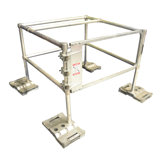
5.0 SYSTEM LAYOUT 5.1 For the HG-KIT-08, the baseplates are placed in a 4-foot square with the closed hatch at the center. The location of the gate would be determined by the access from the hatch, usually a ladder. Typically the system would be set up so the worker comes up the ladder and exits directly through the Self-Closing Gate (SCG). -
Page 13: Installation Hg-Kit-08
6.0 INSTALLATION HG-KIT-08 Appendix Diagram 1 6.1 When assembling the RoofGuard Kit HG-KIT-08, workers should be a safe distance from the roof edge (per local regulations), have the hatch lid closed, and/or be attached to a suitable fall protection system until the setup is complete. 6.2 Baseplates should be set in a square (4-feet between holes) in piles of 2 with the hatch opening in the center of the square. - Page 14 Figure 6: 4-Foot Rail Figure 7: Complete HG-KIT-08 6.6 The mid rails of both sides should also then be inserted between A-POST-END and B-POST-CORNER on both sides, taking care that the top rail does not fall out. Once inserted, the set- screws holding the side rails (both sides) can be tightened to 16ft-lbs.
-
Page 15: Installation Rgc-Kit-09
7.0 INSTALLATION RGC-KIT-09 Appendix Diagram 2 7.1 When assembling the RoofGuard Kit RGC-KIT-09, workers should be back from the roof edge (per local regulations) or be attached to a fall protection system until the setup is complete. 7.2 Clear the area for the RoofGuard baseplates of any snow, ice, or loose dirt/debris. - Page 16 7.7 Along the “hazard” edge, two 9-foot pieces of rail will be secured. Prior to attachment, the stiffener X-POST-INT should be secured to the center of two 9-foot lengths of pipe where they are marked with an X-POST-INT. The 9-foot rail section can then be inserted in the B-POST-CORNER and secured to the other B-POST- CORNER.
-
Page 17: Installation Rgc-Kit-18V
8.0 INSTALLATION RGC-KIT-18V Appendix Diagram 3 8.1 When assembling the RoofGuard Kit RGC-KIT-18V, workers should be back from the roof edge (per local regulations), or be attached to a fall protection system until the setup is complete. 8.2 Clear the area for the RoofGuard baseplates of any snow, ice or loose dirt/debris. - Page 18 8.7 Along the “hazard” edge, two 9-foot pieces of rail will be secured. Prior to attachment, the stiffener X-POST-INT should be secured to the center of two 9-foot lengths of pipe where they are marked with and X-POST-INT. The 9-foot rail section can then be inserted into the B-POST-CORNER and secured to the E-POST-VAR (for RGC-KIT-18V).
-
Page 19: Installation Rgc-Kit-27V
9.0 INSTALLATION RGC-KIT-27V Appendix Diagram 4 9.1 When assembling the RoofGuard Kits RGC-KIT-27V, workers should be back from the roof edge (per local regulations), or be attached to a fall protection system until the setup is complete. 9.2 Clear the area for the RoofGuard baseplates of any snow, ice or loose dirt/debris. - Page 20 9.7 Along the “hazard” edge, two 9-foot pieces of rail will be secured. Prior to attachment, the stiffener X-POST-INT should be secured to the center of the two 9-foot lengths of pipe where they are marked with an X-POST-INT. The 9-foot rail section can then be inserted into the corner B-POST-CORNER and secured to the center E-POST-VAR.
- Page 21 WARNING Warning – Do NOT lean on, or climb on guardrails. Guardrails MUST NOT be used as an anchor for fall restraint or fall arrest, and shall not be used for hoisting or tie-off. Attachment of banners / signs / equipment is not permitted. Excess force applied to the top rail could cause tipping, resulting in injury or death.
-
Page 22: Detailed Inspection And Maintenance Log
10.0 DETAILED INSPECTION AND MAINTENANCE LOG Inspection Items Corrective Action Noted Taken... -
Page 23: Warranty
11.0 LIFTSAFE FALL PROTECTION WARRANTY Equipment offered by Liftsafe Fall Protection (LFP) is warranted against factory defects in workmanship and materials for a period of one year from date of installation or use by the owner, provided that this period shall not exceed 18 months from date of shipment. -
Page 24: Appendix
12.0 APPENDIX DIAGRAMS Diagram 1: HG-KIT-08 Page 24... - Page 25 Diagram 2: RGC-KIT-09 Page 25...
- Page 26 Diagram 3:RGC-KIT-18V Page 26...
- Page 27 Diagram 4: RGC-KIT-27V Page 27...
- Page 28 Liftsafe Fall Protection Inc. 409 Harmony Road Ayr, Ontario N0B 1E0 TF.: 1(800) 977-2005 (519) 896-2430 (519) 896-2085 E.: info@liftsafeinspections.com W.: www.fallsafetysolutions.com...
Need help?
Do you have a question about the RoofGuard RGC-RA and is the answer not in the manual?
Questions and answers