Table of Contents
Advertisement
Available languages
Available languages
Quick Links
Advertisement
Chapters
Table of Contents

Subscribe to Our Youtube Channel
Related Manuals for Sime EASY SYSTEM 1-2 I


Summary of Contents for Sime EASY SYSTEM 1-2 I
- Page 1 Sistema a circolazione forzata Forced-circulation system EASY SYSTEM 1-6I /.1-6FA /.1-6P MANUALE PER L’INSTALLAZIONE E LA MANUTENZIONE INSTALLATION AND SERVICING INSTRUCTIONS Fonderie SIME S.p.A. 7500381 - 02/2021 - R0 ISTRUZIONI ORIGINALI - TRANSLATION OF THE ORIGINAL INSTRUCTIONS...
-
Page 2: Table Of Contents
Caratteristiche........5 EASY SYSTEM 1-2 I 8500180 1.1.1... - Page 3 – Il sistema deve essere destinato all’uso assolutamente essenziale posizionare previsto da che non è responsa- Sime il telaio assicurando che il serbatoio bile per danni causati a persone, ani- dell’acqua si trovi esattamente sopra mali o cose, da errori d’installazione, di...
- Page 4 AVVERTENZE E REGOLE DI SICUREZZA AVVERTENZE – Fonderie SIME S.p.A. si riserva di va- riare in qualunque momento e senza – Dopo l’installazione dell’apparecchio, preavviso i propri prodotti nell’intento pulire l’area circostante. Compilare il di migliorarli senza pregiudicarne le modulo di garanzia e spedirlo al co- caratteristiche essenziali.
-
Page 5: Descrizione Dell'apparecchio
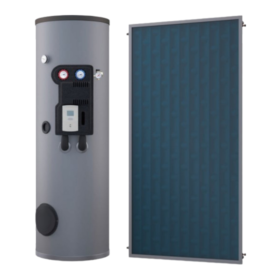
DESCRIZIONE DELL’APPARECCHIO 1.1.3 Funzionamento dell’impianto solare - riscalda- Caratteristiche mento acqua Con l’uso dei sistemi solari a circolazione forzata si ottiene un La superficie del collettore, tramite l’energia solare che assor- risparmio energetico del 70-100%, dato che viene ridotto il tem- be, riscalda il liquido (acqua o soluzione antigelo) che circola nel po di funzionamento del bruciatore nella caldaia o della resi- collettore solare. -
Page 6: Installazione
EASY SYSTEM .1-2 FA bambini il materiale dell’imballo in quanto può es- Quantità Descrizione Codice sere potenziale fonte di pericolo. Deve quindi essere Collettore solare Sime Plano 272 8500073 smaltito secondo quanto stabilito dalla legislazione vigente. Bollitore sanitario BS 2S -C. 200... -
Page 7: Identificazione
I sistemi solari a circolazione naturale Easy System sono identi- Quantità Descrizione Codice ficati da due adesivi, uno posto sul bollitore e l’altro sul collet- Collettore solare Sime Plano 272 8500073 tore, su cui sono riportati tutti i dettagli relativi al sistema. Le Bollitore sanitario BS 2S -C.200... -
Page 8: Bollitore Solare
Bollitore solare 1.7.1 Dimensioni e attacchi BOLLITORE BOLLITORE BS 2S -C. 300 ø est. 45° Fig. 2 BS 2S - C. DIMENSIONI E COLLEGAMENTI IDRAULICI FLANGIA DI ISPEZIONE Attacco est. 168 mm/ int. 114 mm Φ Φ RESISTENZA ELETTRICA Attacco 1”... -
Page 9: Collettore Solare
Gomme di silicone speciali che permettono l’ oscillazione Fig. 4 della lunghezza dell’assorbitore (ritrazione- dilatazione) in tutte le fasce di temperatura da -40˚C fino a +200˚C. COMPONENTE SIME PLANO 272 Superficie totale () 2,72 Copertura di vetro temperato trasparente Mezzo di trasporto del calore... -
Page 10: Gruppo Idraulico Solare
Versione provvista di disaeratore (A) Gruppo idraulico solare I gruppi solari hanno la funzione principale di far circolare il fluido termovettore nel circuito primario e sono comprensivi di pompa solare ad alta efficienza WILO PARA ST 15/7 iPWM (cod. 6330411), valvola di sicurezza, termometri, manometro, rubi- netti di carico - scarico e tutta una serie di componentistiche che servono per il buon funzionamento dell’impianto solare, già... -
Page 11: Centraline Solari
Le configurazioni di apparecchiatura possibili sono tre: gruppo solare – Stand Alone, in cui è presente solo TermoSolis. – Comunicante solo con un remoto Open Therm Sime Home o Sime Home Plus, che prevede la gestione del sistema con un comando remoto. -
Page 12: 1.10.2 Modulo Di Protezione Da Sovravoltaggio
1.10.1.3 Dati tecnici 1.12 Vaso d’espansione solare I vasi d’espansione solari devono essere con la membrana in GENERALI nitrile, in quanto il fluido termovettore che circola nel circuito Alimentazione 230 (+10 ÷ -15) Vac (%) primario è composto da acqua e antigelo propilenico atossico. Frequenza 50 ( ±5 ) Hz (%) -
Page 13: Installazione
INSTALLAZIONE Se la deviazione dall’orientamento corretto è inevitabile, biso- Regole generali gna correggere il rendimento del sistema aumentando la su- perficie dei collettori in base ad uno studio di valutazione delle ATTENZIONE condizioni specifiche. Dato che l’angolo di incidenza della radiazione solare cambia –... -
Page 14: Liquido Antigelo
2.1.6 Liquido antigelo Misure generali di prevenzione Lo speciale mezzo di trasferimento del calore utilizzato nel cir- cuito chiuso protegge il sistema dal congelamento e dall’accu- ATTENZIONE mulo di sale all’interno dei tubi del collettore. L’intercapedine – Durante l’installazione dei sistemi termici solari e in cui ha luogo la circolazione del mezzo di trasferimento del delle relative tubazioni rispettare le istruzioni sulla calore non comunica con il serbatoio per l’accumulo dell’acqua. -
Page 15: Tipologie D'installazione Dei Collettori
2.4.2 Sistemi di fissaggio Tipologie d’installazione dei collettori Per il fissaggio dei collettori Sime mette a disposizione le se- Su tetto inclinato parallelamente alla falda, sopra alle tegole. guenti tipologie di telaio: sulla falda in parallelo sopra alle tego- le, ad incasso nelle tegole e su tetto piano. -
Page 16: Requisiti Generali Di Installazione
Esempio: in figura errore di installazione, il collettore non riceve Requisiti generali di installazione sole. 2.5.1 Orientamento collettori Il collettore solare, per una resa ottimale, deve essere rivolto verso SUD. Una deviazione di 15-20° è accettabile. Fig. 16 NORD/OVEST NORD/EST Raddoppiando all’in- NORD Raddoppiando all’in-... - Page 17 Gli automatismi del sistema controllano continuamente la dif- Tutti i componenti sono adatti per miscela di acqua - propile- ferenza di temperatura tra i collettori solari e il bollitore e for- noglicole. niscono i relativi comandi in moda da assicurare la fornitura In riferimento allo schema di seguito riportato: ininterrotta di acqua calda in base alle regolazioni del circuito.
-
Page 18: Montaggio
2.7.3 Tubazioni isolamento Montaggio I tubi che collegano il collettore con il gruppo di regolazione so- lare o il bollitore, devono essere in rame o in acciaio inox. 2.7.1 Collettori solari È VIETATO Per un utilizzo annuale, si utilizza in Italia il traliccio inclinato a Le tubazioni non dovranno mai essere in acciaio zin- 35°... -
Page 19: Vasi Espansione Solari
Se comunque, per motivi strutturali, si dovessero costruire del- 2.7.5 Miscelatore termostatico le “Cuspidi”, occorrerà inserire delle valvole di sfiato, sia sulla Il miscelatore termostatico deve essere installato in uscita dal mandata che sul ritorno. bollitore sanitario, prima che l’acqua vada all’utenza (per evita- re ustioni alle persone), secondo quanto riportato nello schema d’impianto allegato (vedi esempio a lato). -
Page 20: Messa In Funzione
MESSA IN FUNZIONE – Verificare nuovamente la pressione ed eventualmente ripri- Caricamento impianto stinare aprendo il rubinetto (A) e il rubinetto dell’acqua. – Controllare a vista accuratamente tutti i tubi e i raccordi, per verificare che non presentino perdite e lasciare l’impianto in 3.1.1 Pulizia del circuito solare pressione per qualche ora per verificare eventuali cali di pres-... -
Page 21: Impostazione Centralina Solare
La pressione di caricamento a freddo dell’impianto deve essere – Se non si è ancora provveduto, applicare la coibentazione alle di 1,2 - 1,5 bar nel collettore solare. Se il punto di caricamento tubazioni del circuito solare congiungendola in tutti i punti dell’impianto è... -
Page 22: Esempio Schema Di Impianto
Esempio schema di impianto COMPONENTI COMPRESI NEL KIT EASY SYSTEM COMPONENTI COMPRESI NEL KIT EASY SYSTEM N.B. Prevedere un sifone all’entrata e all’uscita del gruppo idraulico per SONDA evitare circolazioni parassite. A = almeno 10 XØ tubazione Protezione da sovratensioni per sonda collettore Acqua calda Acqua calda... -
Page 23: Lista Di Controllo
Lista di controllo Istruzioni per l’installatore Una volta completata l’installazione, con l’aiuto della lista di controllo sottostante l’installatore deve controllare tutti i punti indicati e contrassegnare la colonna pertinente con un √. LISTA CONTROLLO COLLETTORI E TUBI ESTERNI L'installazione e il fissaggio del telaio di supporto è stato effettuato secondo le istruzioni e le norme attualmente in vigore? La posizione e l'orientamento dei collettori solari è... -
Page 24: Possibili Problemi - Soluzioni
POSSIBILI PROBLEMI - SOLUZIONI Impianto 1. L’IMPIANTO NON RISCALDA O NON RISCALDA BENE CAUSA SOLUZIONE Con impianto a caldo, sfiatare la valvola di sfogo aria sui collettori e il degasatore sul gruppo Aria nell’impianto solare. Ripetere l’operazione per alcuni giorni. Pompa bloccata Aprire e chiudere la pompa per sbloccarla, eventualmente sostituirla. - Page 25 4. PERDITA VALVOLA SICUREZZA CAUSA SOLUZIONE Pressione eccessiva nell’impianto che provoca Ripristinare a freddo il fluido termovettore nell’impianto, rimetterlo in pressione e sfiatare a apertura valvola sicurezza caldo. Precarica troppo bassa o troppo alta nel vaso Portare la precarica dal vaso di espansione solare a 0,3 bar in meno rispetto alla pressione di espansione caricamento a freddo dell’impianto.
-
Page 26: Pompa Para St 15/7 Ipwm Del Gruppo Solare
Pompa PARA ST 15/7 iPWM del gruppo solare Colore LED Eventuale anomalia Causa Possibile rimedio Il sistema idraulico della pompa viene Funzionamento turbina alimentato, ma la pompa non ha tensione Verificare la tensione di rete di rete Rosso-Verde Funzionamento a secco Aria nella pompa Verificare l’assenza di perdite nell’impianto lampeggiante... -
Page 27: Manutenzione
MANUTENZIONE AVVERTENZA – Le operazioni di seguito descritte devono essere effettuate SOLO da personale professionalmente qualificato con l’OBBLIGO di indossare adeguate pro- tezioni antinfortunistiche. – Accertarsi che le temperature dei componenti o del- le tubazioni dell’impianto non siano elevate (perico- lo di ustioni). -
Page 28: Termini E Limitazioni Della Garanzia
TERMINI E LIMITAZIONI DELLA SMALTIMENTO GARANZIA La garanzia è valida quando sono soddisfatte le seguenti carat- Smaltimento dell’apparecchio (Direttiva teristiche di qualità dell’acqua: Europea 2012/19/UE) – Indice di saturazione (Langelier): LSI > 0,1 L’apparecchio ed i dispositivi elettrici ed elet- tronici, provenienti da nuclei professionali o –... -
Page 29: Programmazione Interventi
PROGRAMMAZIONE INTERVENTI Data di acquisto e installazione: Data Dati tecnico e la firma manutenzione manutenzione manutenzione maintenance manutenzione manutenzione manutenzione manutenzione manutenzione... - Page 30 CODE Characteristics ....... . 33 EASY SYSTEM 1-2 I 8500180 1.1.1...
- Page 31 – The system must be used as intend- frame must be positioned by ensuring ed by which cannot be held lia- Sime that the water tank lies exactly above a ble for any harm caused to people or horizontal support and never between damage to animals or objects due to two pillars.
- Page 32 SAFETY WARNINGS AND RULES WARNINGS – Fonderie SIME S.p.A. reserves the right to make changes to its products – Clean the surrounding area once the at any time and without prior notice in appliance has been installed. Fill in order to improve them without alter- the warranty form and send it to the ing their essential characteristics.
-
Page 33: Description Of The Appliance
DESCRIPTION OF THE APPLIANCE 1.1.3 Operation of the solar system - water heating Characteristics The surface of the collector, through the solar energy it absorbs, The use of forced-circulation solar heating systems allow for heats the liquid (water or anti-freeze solution) that circulates saving up to 70–100% energy, given that the burner in the boil- inside the solar heating collector. -
Page 34: Installation
Quantity Description Code WARNING SimeSol 230 solar heating collector 8500002 The appliance must only be installed by the Sime Tech- BS 2S -C 400 DHW calorifier 8106877 nical Assistance Service or by qualified professionals Module for protecting the control unit against who MUST wear suitable protective safety equipment. -
Page 35: Identification
Easy System Quantity Description Code identified by two stickers, one attached to the calorifier and the Sime Plano 272 solar heating collector 8500073 other on the solar collector, which contain all the details rel- BS 2S -C. 200 DHW calorifier 8106880 ative to the system. -
Page 36: Solar Calorifier
Solar calorifier 1.7.1 Dimensions and fittings BS 2S -C. 300 CALORIFIER ext. ø ø est. 45° Fig. 2 BS 2S - C. DIMENSIONS AND WATER CONNECTIONS INSPECTION FLANGE Fitting 168 mm/int. 114 mm ext. Φ Φ HEATING ELEMENT Fitting 1”1/2 1384 1411 THERMOMETER... -
Page 37: Solar Heating Collector
Special silicone rubbers allow the absorber to expand or con- tract in all temperature ranges from –40°C to +200°C. COMPONENT SIME PLANO 272 Total surface area () 2.72 Clear tempered glass cover... -
Page 38: Solar Hydraulic Unit
Version equipped with a deaerator (A) Solar hydraulic unit Solar units have the main function of making the heat-trans- fer fluid circulate in the primary circuit and are supplied with the high-efficiency solar pump WILO PARA ST 15/7 iPWM (code 6330411), safety valve, thermometers, pressure gauge, fill- ing-drainage valves and a series of components to make the solar system function efficiently, already pre-assembled and... -
Page 39: Solar Control Units
Sime Home Plus remote control, whereby the system is man- aged with a remote control. – Full System, the full system solution, in which other Sime devices are connected for full control of the space heating and hot water systems. -
Page 40: 1.10.2 Overvoltage Protection Module
1.10.1.3 Specifications 1.12 Solar expansion vessel Solar expansion vessels must have a nitrile membrane, as the GENERAL heat-transfer fluid circulating in the primary circuit is made up Power supply 230 (+10 to –15) of water and non-toxic propylene anti-freeze liquid. Frequency 50 ( ±5 ) Hz (%) -
Page 41: Installation
INSTALLATION If the deviation from the correct direction is inevitable, the sys- General rules tem’s performance must be corrected by increasing the surface of the collectors on the basis of an assessment of the specific WARNING conditions. Given that the angle of impact of the sun’s rays varies with the –... -
Page 42: Anti-Frost Liquid
2.1.6 Anti-frost liquid General prevention measures The special heat-transfer liquid used in the closed circuit pro- tects the system against freezing and the build-up of salt inside WARNING the collector’s pipes. The gap in which the heat-transfer fluid – When installing solar thermal systems and the rel- circulates does not communicate with the water storage tank. -
Page 43: Types Of Collector Installation
Fig. 13 2.4.1 Couplings The solar collectors must be connected using the appropriate couplings which Sime provides depending on the types of in- stallation. Description Connection kit for the forced-circulation solar heating system for connecting solar connectors, made up of: –... -
Page 44: General Installation Requirements
Example: the picture shows an incorrect installation, since the General installation requirements collector does not receive any sunlight. 2.5.1 Collector orientation For optimal performance, the solar collector must face SOUTH- WARDS. A 15°–20° deviation is acceptable. Fig. 16 NORTH/WEST NORTH/EAST Roughly doubling the NORTH Roughly doubling the... - Page 45 The system’s automatic components continuously monitor the All the components are suitable for water propylene-glycol temperature difference between the solar collectors and the mixtures. calorifier and send the relative commands to ensure an unin- With reference to the diagram shown below: terrupted supply of hot water based on the settings made on –...
-
Page 46: Assembly
2.7.3 Insulation piping Assembly The pipes connecting the collector with the solar adjustment unit or the calorifier must be made of copper or stainless steel. 2.7.1 Solar heating collectors FORBIDDEN For year-round use, in Italy we tilt the frame by 35° (for exam- The pipes must never be made of galvanised steel due ple: residential buildings). -
Page 47: Solar Expansion Vessels
Nonetheless, if cusps are necessary due to structural reasons, 2.7.5 Thermostatic mixer relief valves must be mounted on both the delivery and return The thermostatic mixer must be installed on the output side sides. of the DHW calorifier, before the water reaches the withdrawal point (to avoid scalding), as indicated in the enclosed system diagram (see adjacent example). -
Page 48: Initial Start-Up
INITIAL START-UP – Visually inspect all the pipes and couplings carefully for any System filling losses and leave the system pressurised for a few hours to verify whether any pressure losses occur. 3.1.1 Cleaning the solar circuit The system can be operated for a while in trial mode only with Two cocks are used for cleaning and filling the circuit: one for the recirculation water to adequately verify whether there are filling and the other for discharging, separated by a shut-off... -
Page 49: Setting The Solar Control Unit
The system’s cold charge pressure must be 1.2–1.5 bar in the – If it has not yet been done, apply insulating material on the solar collector. If the system’s filling point is located on the pipes of the solar circuit by joining all points without leaving central heating device, it is necessary to also add the pressure any gaps, or by gluing it. -
Page 50: Example Of System Scheme
Example of system scheme COMPONENTI COMPRESI NEL KIT EASY SYSTEM COMPONENTS INCLUDED IN THE EASY SYSTEM KIT N.B.: mount a siphon on the hydraulic unit inlet and outlet to SENSOR prevent parasitic circulations. A = at least 10 x pipe Ø Overvoltage pro- tection device for collector sensor... -
Page 51: Checklist
Checklist Instructions for the installer After completing the installation, the installer must check all the indicated points with the aid of the checklist shown below and tick the relevant column with a √. LIST CHECK COLLECTORS AND EXTERNAL PIPES Was the support frame installed and fastened according to the instructions and the regulations currently in force? Are the solar collectors optimally positioned and oriented? Is there any moisture inside the solar collectors? Were the hydraulic connections to the solar collectors made correctly? -
Page 52: Troubleshooting
TROUBLESHOOTING System 1. THE SYSTEM DOES NOT HEAT OR HEATS POORLY CAUSE SOLUTION With the system hot, bleed the air relief valve on the collectors and the degasser on the Air in the system solar unit. Repeat the operation for a few days. Pump seized up Open and close the pump to free it up, or replace it if necessary. - Page 53 4. SAFETY VALVE LEAKAGE CAUSE SOLUTION Excessive pressure in the system that causes With the system cold, restore the heat-transfer fluid in the system, raise it to the right pres- the safety valve to open sure and then bleed the system when hot. Pre-charge pressure too low or too high in the Adjust the pre-charge pressure in the solar expansion vessel to 0.3 bar less than the sys- expansion vessel...
-
Page 54: Para St 15/7 Ipwm Pump Of The Solar Unit
PARA ST 15/7 iPWM pump of the solar unit LED colour Anomaly Cause Possible solution The hydraulic system in the pump is Turbine operation powered but the pump is not receiving Check the network voltage any mains voltage Red/Green Dry operation Air in the pump Check for leaks in the system flashing... -
Page 55: Maintenance
MAINTENANCE WARNING – The maintenance operations described below must ONLY be carried out the professionally qualified personnel who MUST wear suitable protective safety equipment. – Make sure that the system components and pipes are not hot (risk of burns). – Periodic maintenance must be carried out every two years by an authorised technician or by per- sonnel of the manufacturer’s technical assistance service. -
Page 56: Warranty Terms And Conditions And Limitations
WARRANTY TERMS AND DISPOSAL CONDITIONS AND LIMITATIONS The warranty is only valid when the following water quality Disposal of the equipment (European characteristics are satisfied: Directive 2012/19/EU) – Saturation index (Langelier): LSI > 0.1 At the end of their life span, the appliance and electrical and electronic devices deriving from –... -
Page 57: Schedule Of Interventions
SCHEDULE OF INTERVENTIONS Date of purchase and installation: Date Technical data and signature maintenance maintenance maintenance maintenance maintenance maintenance maintenance maintenance maintenance... - Page 60 Fonderie Sime S.p.A - Via Garbo, 27 - 37045 Legnago (Vr) Tel. +39 0442 631111 - Fax +39 0442 631292 - www.sime.it...
Need help?
Do you have a question about the EASY SYSTEM 1-2 I and is the answer not in the manual?
Questions and answers