
Related Manuals for Fisher & Paykel OR30SCI


Summary of Contents for Fisher & Paykel OR30SCI
- Page 1 FREESTANDING COOKER OR30SDI & OR30SCI Induction & OR30SDE Glass Ceramic models INSTALLATION GUIDE US CA 591507D 10.19...
-
Page 2: Table Of Contents
CONTENTS Safety and warnings Parts supplied for installation Tools needed for installation (not supplied with the appliance) Model identification Prior to installation Product dimensions Clearance dimensions Fitting the optional backguard Location of electrical supply Ventilation requirements Fitting the adjustable feet Moving the range Installing the anti-tip bracket Electrical connection... -
Page 3: Safety And Warnings
SAFETY AND WARNINGS Installation IMPORTANT SAFETY INSTRUCTIONS! WARNING! Electrical shock hazard Save these instructions for the local inspectors use. ● ● Before carrying out any work on the electrical section of the appliance, To avoid hazard, follow these instructions carefully before installing or using this ●... - Page 4 SAFETY AND WARNINGS IMPORTANT SAFETY INSTRUCTIONS! GENERAL INSTALLATION INFORMATION Cleaning and servicing A risk of the appliance tipping over exists if the appliance is not installed in accordance ● ● with installation instructions. Service should only be performed by an authorized technician. ●...
-
Page 5: Parts Supplied For Installation
PARTS SUPPLIED FOR INSTALLATION Screws and plastic Cupped washer* Anti-tip bracket (1) Small screws and Bolt (1) Threaded nuts (2) Wood screws (8) Ground lead* washers (2) sleeve anchors (8) (3 wire permanent (4 wire permanent connection) connection) *Can be used in US only, for Canada it is mandatory to connect the range by using cordset with plug supplied. -
Page 6: Model Identification
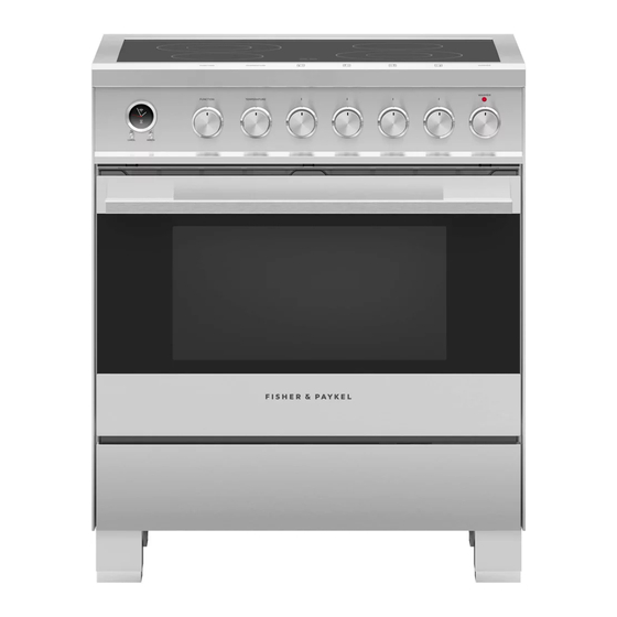
MODEL IDENTIFICATION NOTE: Model features may vary 30” INDUCTION MODELS 30” CERAMIC MODELS OR30SDI6 OR30SDE6 OR30SCI6 PRIOR TO INSTALLATION Unpacking and handling Inspect the range to verify that there is no shipping damage. If any damage is detected, call the shipper and initiate a damage claim. Fisher & Paykel is not responsible for shipping damage. ●... -
Page 7: Product Dimensions
PRODUCT DIMENSIONS NOTE: Model features may vary Optional kickstrip shown is available (purchased separately) FRONT SIDE OR30SDI / OR30SCI OR30SDE PRODUCT DIMENSIONS inches (mm) inches (mm) Overall height of range min 35 3/4” (908) min 35 3/4” (908) max 37 5/8” (956) max 37 5/8”... -
Page 8: Clearance Dimensions
(see diagrams following) copper. Front Note This range may be installed directly ● ● adjacent to existing 36” (914mm) high OR30SDI / OR30SCI OR30SDE base cabinets. CLEARANCE DIMENSIONS If the range is to be placed adjacent ● ● inches (mm) -
Page 9: Fitting The Optional Backguard
place. • The island trim is already fitted to the appliance while the backguard can be purchased as a FITTING THE OPTIONAL BACKGUARD Fig. 1.3a separate kit. Fig. 1.2 • If replacing the island trim with the backguard, assemble it by using the same screws/spacers used for fixing the island trim (figures 1.3a, Island trim and backguard 12 x... -
Page 10: Ventilation Requirements
VENTILATION REQUIREMENTS A suitable ventilation hood may be installed above the range. Fisher & Paykel has a choice of ventilation hoods designed to match the rest of our kitchen appliance family. See fisherpaykel.com or your local dealer for more details. Hood (inc. -
Page 11: Fitting The Adjustable Feet
FITTING THE ADJUSTABLE FEET Fitting the adjustable feet Fitting the adjustable feet covers (optional) The adjustable feet must be fitted to the base of the range before use. If using the adjustable feet covers fit these while the range is tipped over. Rest the rear of the range on a piece of the polystyrene packaging exposing the base for the fitting of the feet. -
Page 12: Moving The Range
MOVING THE RANGE IMPORTANT! When raising the range to upright position always ensure two ● ● people carry out this manoeuvre to prevent damage to the adjustable feet. Be careful: do not lift the range by the oven door handle, the ●... -
Page 13: Installing The Anti-Tip Bracket
INSTALLING THE ANTI-TIP BRACKET The anti-tip bracket has two components: the adjustable bracket ● ● the stability bracket ● ● IMPORTANT! You must install both parts of the anti-tip bracket and ensure they are properly fitted together to prevent the range from tipping. To fit the anti-tip bracket 1 Thread the bolt through the adjustable bracket and fix in place using the two supplied nuts. - Page 14 INSTALLING THE ANTI-TIP BRACKET 3 Fix the stability bracket in place. It can be fixed as follows: To the floor OR on the rear wall by 4 screws (supplied). ● ● To the floor AND on the rear wall by 8 screws (supplied). ●...
-
Page 15: Electrical Connection
ELECTRICAL CONNECTION IMPORTANT! WARNING! This cooker must be connected to the electricity supply only by an authorised person. Your cooker is supplied with a certified 4 prong NEMA 14-50P power cord for your protection against shock hazard and should be plugged directly into a properly grounded socket. - Page 16 ELECTRICAL CONNECTION 4-Wire Connection 3-Wire Connection (using supplied Ground lead) PERMANENT CONNECTION (HARD WIRING) 1 Loosen the L1 (black), L2 (red) and neutral (white) screws. 1 Loosen the L1 (black), L2 (red) and neutral (white) screws. US only, for Canada it is mandatory to connect 2 Mount the conduit fitting to the 1 1/8”...
-
Page 17: Final Checklist
FINAL CHECKLIST TO BE COMPLETED BY THE INSTALLER GENERAL Placement of unit. Specified clearance maintained to cabinet surfaces. Unit Level – front to back, side to side. All packaging material and tie straps removed. Island trim or optional backguard correctly attached. The anti-tip bracket is correctly installed.
Need help?
Do you have a question about the OR30SCI and is the answer not in the manual?
Questions and answers