
Related Manuals for FirePro FPC-2V2


Summary of Contents for FirePro FPC-2V2
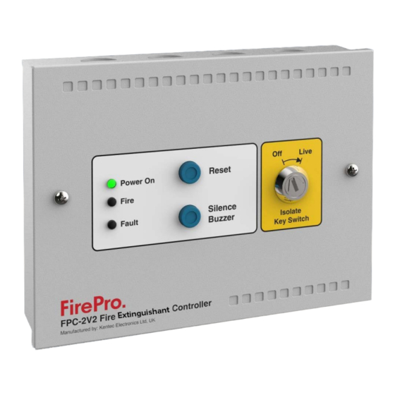
- Page 1 FPC - 2V2 Fire Extinguishant Controller Operation and Installation Manual Issue March 2021 Version 1.0...
-
Page 2: Table Of Contents
3. Terminal details ................6 3.1 Power terminals 24V IN/24V OUT ..........6 3.2 Detection terminals ..............6 3.3 FirePro Condensed Aerosol Generators connection terminals ..7 3.4 FIRE contacts for remote signalling ..........8 3.5 FAULT contacts for remote signalling .......... 8 3.6 Sounder circuit wiring ............... -
Page 3: Overview
FirePro disconnection of any of these will announce a fault condition. The FPC-2V2 requires a battery backed 24 V DC power supply capable of delivering a minimum of 1.6A for a short period to operate the Condensed Aerosol Generators. Terminals are provided for incoming and outgoing connection of the 24 V DC power supply. -
Page 4: Operation
Reset button on the front of the controller. Note: The controller will continue to show a fault condition until the Condensed Aerosol Generators are replaced. Man-1556 Rev.02 FPC-2V2 Fire Extinguishant Controller Operation and Installation Manual Page 4 of 18... -
Page 5: Installation
2. Installation The front panel of the FPC-2V2 should be removed by loosening the two M4 fixing screws holding it in place and should be put in a safe place along with the screws for refitting later. The back box can then be used to mark the fixing position holes in the required place. -
Page 6: Terminal Details
3.1 Power terminals 24V IN/24V OUT These are the power supply terminals. The polarity of these terminals is very important. If connecting multiple FirePro. FPC-2 V2 units to a single power supply the 24V DC must be wired as shown in Figure 3 below. -
Page 7: Firepro Condensed Aerosol Generators Connection Terminals
Figure 4- Connection to linear heat detection cable Figure 5- Connection to smoke detectors 3.3 FirePro Condensed Aerosol Generators connection terminals These terminals (“FIREPRO GEN1” to “FIREPRO GEN4”) are for the connection of FirePro Condensed Aerosol Generators. Test lamps are provided in the terminals to allow testing of the system before connecting the Condensed Aerosol Generators. -
Page 8: Fire Contacts For Remote Signalling
There is no dedicated Siren circuit on this FPC-2V2 panel, however a siren can be connected to the fire relay output. The “FIRE” terminal on the FPC-2V2 panel is a relay that creates a closed circuit upon activation of the panel. This can be used to activate a siren or other device when wired as shown in Figure 7. -
Page 9: Connection To Addressable Modules
3.7 Connection to addressable modules It is possible to configure the FPC-2V2 panel such that it will trigger a VMMI1000 addressable module with fire and fault signals via FIRE and FAULT relay contacts. To make the FPC-2V2 panel compatible with an addressable input module, move jumpers J1 and J2 from their default positions (position A) to position B. -
Page 10: Testing And Commissioning
CONDENSED AEROSOL GENERATORS BEFORE TESTING. With all FirePro Condensed Aerosol generators disconnected from the FPC-2V2 panel, ensure that the test lamps that are supplied with the unit are fitted to terminals FirePro GEN1, FirePro GEN2, FirePro GEN3 and FirePro GEN4 IMPORTANT... - Page 11 Figure 10 – Connections to FirePro Gen outputs to test system. Live Live Isolate Isolate Key Switch Key Switch Figure 11 – Isolate Key Switch “Off” and “Live” Man-1556 Rev.02 FPC-2V2 Fire Extinguishant Controller Operation and Installation Manual Page 11 of 18...
-
Page 12: System Test
Step 2 Turn Isolate Key Switch to “Off” position. Step 3 Disconnect the FirePro Generators and ensure that the test lamps are fitted to the terminals. Step 4 Ensure both jumper links (J1 & J2) are fitted in position A Step 5 Inspect all system components (Detectors, Sirens etc.) and all cables for... -
Page 13: Condensed Aerosol Generator Monitoring Test
LED on the front panel and the internal yellow LED marked LED5 are lit and the buzzer sounds. Step 18 Turn the Isolate Key Switch to the “Live” position and ensure that the fault indication clears. Man-1556 Rev.02 FPC-2V2 Fire Extinguishant Controller Operation and Installation Manual Page 13 of 18... -
Page 14: Testing And Commissioning
Turn the Isolate Key Switch to the “Off” position. Step 3 Remove the front frame panel. Step 4 Disconnect the FirePro Generators and ensure the test lamps are fitted to the terminals. Step 5 Inspect all components – detectors, sirens etc. -
Page 15: Fuse Replacement
Step 21 Power off the unit. Step 22 Turn Isolate Key Switch to “Off” position. Step 23 Disconnect the test lamps and ensure that the FirePro Generators fitted to terminals. Step 24 Place the front frame of the panel. Step 25 Power on the unit. -
Page 16: Specifications
BS OO A 05 light grey textured Panel environmental class Class A and is designed for indoor use only Operating temperatures -5oC (+/- 3) and +40oC (+/- 2) Maximum relative humidity Man-1556 Rev.02 FPC-2V2 Fire Extinguishant Controller Operation and Installation Manual Page 16 of 18... -
Page 17: Indicative System Diagram
7. Indicative system diagram Figure 12- Example of connection to addressable fire alarm panel Man-1556 Rev.02 FPC-2V2 Fire Extinguishant Controller Operation and Installation Manual Page 17 of 18... - Page 18 (including negligence), strict liability or otherwise, even if advised of the possibility of such damages. FirePro is constantly updating its products and systems to the state of the art and therefore reserves the right to make changes in design, equipment, and technology. You cannot therefore base any claims on the data, illustrations or descriptions contained in this literature.
- Page 19 FirePro Systems Ltd 8 Faleas Street, CY-4101 Limassol, Cyprus - EU Tel.: +357 25 379999 | Fax: +357 25 354432 | Email: mail@firepro.com www.firepro.com...
Need help?
Do you have a question about the FPC-2V2 and is the answer not in the manual?
Questions and answers