Table of Contents
Advertisement
SERVICE MANUAL
2003
04
86732
GR-D60EK,GR-D60E
For disassembling and assembling of MECHANISM ASSEMBLY, refer to the SERVICE MANUAL No.86700 (MECHANISM ASSEMBLY).
Regarding service information other than these sections, refer to the service manual No. 86733 (GR-D70EX).
Also, be sure to note important safety precautions provided in the service manual.
SPECIFICATION
Camcorder
General
Power supply
: DC 11.0 V
DC 7.2 V
Power consumption
LCD monitor off,
viewfinder on
: Approx. 3.4 W
LCD monitor on,
viewfinder off
: Approx. 4.7 W
Dimensions
(W x H x D)
: 69 mm x 94 mm x 143 mm
(with the LCD monitor closed and the viewfinder pushed
back in)
Weight
: Approx. 525 g
Operating temperature
: 0°C to 40°C
Operating humidity
: 35% to 80%
Storage temperature
: -20°C to 50°C
Pickup
: 1/6" CCD
Lens
: F 1.6, f = 2.7 mm to 43.2 mm, 16:1 power zoom lens
Filter diameter
: Ø37 mm
LCD monitor
: 2.5" diagonally measured, LCD panel/TFT active
matrix system
Viewfinder
: Electronic viewfinder with 0.24" black/white LCD
Speaker
: Monaural
Digital Video Camera
Format
: DV format (SD mode)
Signal format
: PAL standard
Recording/Playback format : Video: Digital component recording
: Audio: PCM digital recording,
32 kHz 4-channel (12-bit),
48 kHz 2-channel (16-bit)
Cassette
: Mini DV cassette
Specifications shown are for SP mode unless otherwise indicated. E & O.E. Design and specifications subject
to change without notice.
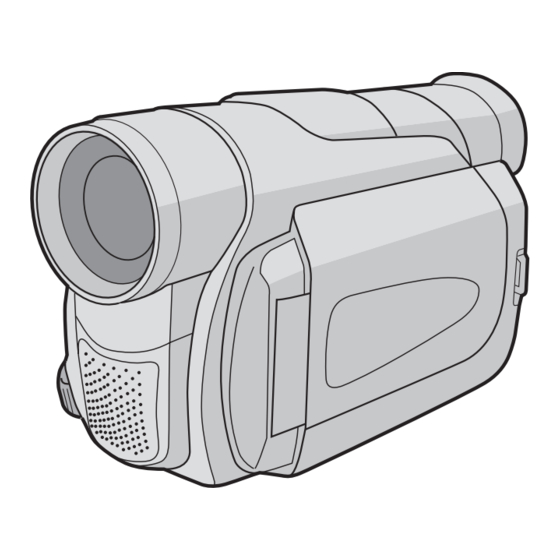
DIGITAL VIDEO CAMERA
(Using AC Adapter)
(Using battery pack)
COPYRIGHT © 2003 VICTOR COMPANY OF JAPAN, LTD.
,GR-D60E
X
PAL
Tape speed
: SP : 18.8 mm/s
LP : 12.5 mm/s
Maximum recording time
: SP : 80 min.
(using 80 min. cassette)
LP : 120 min.
Digital Still Camera Function
Storage media
: SD Memory Card/MultiMediaCard
Compression system
: JPEG (compatible)
File size
: 2 modes (1024 x 768 pixels, 640 x 480 pixels)
Picture quality
: 2 modes (FINE/STANDARD)
Approximate number of
storable images
: pg. 18.
Connectors
S-Video
: Y : 1 V (p-p), 75 Ω, analogue
Output
C : 0.29 V (p-p), 75 Ω, analogue
: Y : 0.8 V (p-p) -1.2 V (p-p), 75 Ω, analogue
Input*
C : 0.2 V (p-p) -0.4 V (p-p), 75 Ω, analogue
AV
: 1 V (p-p), 75 Ω, analogue
Video output
: 0.8 V (p-p) -1.2 V (p-p), 75 Ω, analogue
Video input*
Audio output
: 300 mV (rms), 1 kΩ, analogue, stereo
Audio input*
: 300 mV (rms), 50 kΩ, analogue, stereo
DV
Output
: 4-pin, IEEE 1394 compliant
Input
: 4-pin, IEEE 1394 compliant
USB*
: 5-pin
EDIT
: Ø3.5 mm, 2-pole
* GR-D70 only
AC Adapter
Power requirement
: AC 110 V to 240 V ~, 50 Hz/60 Hz
Output
: DC 11 V
GR-D60EK,GR-D60EX,GR-D60EY M3D126
Y
, 1 A
No.86732
2003/04
Advertisement
Table of Contents

Related Manuals for JVC GR-D60EK


Summary of Contents for JVC GR-D60EK
- Page 1 Output : DC 11 V , 1 A Specifications shown are for SP mode unless otherwise indicated. E & O.E. Design and specifications subject to change without notice. GR-D60EK,GR-D60EX,GR-D60EY M3D126 COPYRIGHT © 2003 VICTOR COMPANY OF JAPAN, LTD. No.86732 2003/04...
- Page 3 DIFFERENCE LIST DIFFERENT TABLE OF FEATURE The following table indicate main different points between models GR-D70EX, GR-D60EK, GR-D60EX and GR-D60EY. ITEM GR-D70EX GR-D60EK GR-D60EX GR-D60EY ← ← DV TERMINAL IN/OUT OUT ONLY ← ← ANALOG INPUT ← POWER CORD CEE TYPE...
- Page 4 VICTOR COMPANY OF JAPAN, LIMITED AV & MULTIMEDIA COMPANY CAMCORDER CATEGORY 12, 3-chome, Moriya-cho, kanagawa-ku, Yokohama, kanagawa-prefecture, 221-8528, Japan (No.86732) Printed in Japan 200304WPC...
- Page 5 MODEL MARK GR-D60EK GR-D60EX GR-D60EY PARTS LIST 2. PARTS LIST MAIN BOARD ASSEMBLY <01> Symbol No. Part No. Part Name Description Local Symbol No. Part No. Part Name Description Local Q2202 UMX1N-W PAIR TRANSISTOR Q2202 or BC847S-X PAIR TRANSISTOR...
- Page 6 MODEL MARK GR-D60EK GR-D60EX GR-D60EY Symbol No. Symbol No. Part No. Part Name Description Local Part No. Part Name Description Local C2607 NCBA1HK-102W C CAPACITOR 1000pF 50V K C1001 NDCA1HJ-8R0W C CAPACITOR 8pF 50V J C2608 NCBA1HK-102W C CAPACITOR...
- Page 7 MODEL MARK GR-D60EK GR-D60EX GR-D60EY Symbol No. Symbol No. Part No. Part Name Description Local Part No. Part Name Description Local C3859 NCBA1CK-103W C CAPACITOR 0.01uF 16V K C6004 NCB21CK-105X C CAPACITOR 1uF 16V K C3860 NCBA1AK-104W C CAPACITOR 0.1uF 10V K...
- Page 8 MODEL MARK GR-D60EK GR-D60EX GR-D60EY Symbol No. Symbol No. Part No. Part Name Description Local Part No. Part Name Description Local C8025 NCBA1AK-104W C CAPACITOR 0.1uF 10V K R1075 NRSA6AJ-473W MG RESISTOR 47kΩ 1/16W J C8026 NCBA1AK-104W C CAPACITOR 0.1uF 10V K...
- Page 9 MODEL MARK GR-D60EK GR-D60EX GR-D60EY Symbol No. Symbol No. Part No. Part Name Description Local Part No. Part Name Description Local R3002 NRSA6AJ-103W MG RESISTOR 10kΩ 1/16W J R4319 NRSA6AJ-0R0W MG RESISTOR 0Ω 1/16W J R3004 NRSA6AJ-103W MG RESISTOR 10kΩ...
- Page 10 MODEL MARK GR-D60EK GR-D60EX GR-D60EY Symbol No. Symbol No. Part No. Part Name Description Local Part No. Part Name Description Local R4871 NRSA6AJ-0R0W MG RESISTOR 0Ω 1/16W J R6701 NRZ0058-R20X MG RESISTOR 0.2Ω 1/2W J R4874 NRSA6AJ-0R0W MG RESISTOR 0Ω...
- Page 11 J501 NNZ0041-001X D CONNECTOR IEEE1394(4pin) J502 QNZ0616-001 USB CONNECTOR X1001 NAX0578-001X CRYSTAL X1002 NAX0564-001X CRYSTAL X3002 NAX0480-001X CRYSTAL 24.576MHz X5501 NAX0587-001X X8301 NAX0522-001X C RESONATOR 6.000MHz LY30030-071A SPACER(A) LY44158-001A SHEET(SHIELD) QAL0474-001 MAIN-PREMDA(x2) (WPC)-200304 (No.86732)3-7 E. & O.E. No.86732 (WPC)-M3D126 GR-D60EK,GR-D60EX,GR-D60EY...
- Page 12 SERVICE MANUAL DIGITAL VIDEO CAMERA 86733 2003 GR-D70EK,GR-D70E GR-D70E ,GR-D70E For disassembling and assembling of MECHANISM ASSEMBLY, refer to the SERVICE MANUAL No.86700 (MECHANISM ASSEMBLY). SPECIFICATION Camcorder Tape speed : SP : 18.8 mm/s LP : 12.5 mm/s General Maximum recording time : SP : 80 min.
-
Page 13: Table Of Contents
TABLE OF CONTENTS PRECAUTIONS ............... .1-3 SAFTY PRECAUTIONS . -
Page 14: Precautions
SECTION 1 PRECAUTIONS 1.1 SAFTY PRECAUTIONS Prior to shipment from the factory, JVC products are strictly in- quently, when servicing these products, replace the cathode spected to conform with the recognized product safety and elec- ray tubes and other parts with only the specified parts. Under trical codes of the countries in which they are to be no circumstances attempt to modify these circuits.Unautho-... - Page 15 1.1.2 Safety Check after Servicing Examine the area surrounding the repaired location for damage (4) Leakage current test or deterioration. Observe that screws, parts and wires have been Confirm specified or lower leakage current between earth returned to original positions, Afterwards, perform the following ground/power cord plug prongs and externally exposed ac- tests and confirm the specified values in order to verify compli- cessible parts (RF terminals, antenna terminals, video and...
-
Page 16: Specific Service Instructions
SECTION 2 SPECIFIC SERVICE INSTRUCTIONS 2.1 BEFORE ASSEMBLY AND DISASSEMBLY 2.1.1 Precautions 2.1.4 Disconnection of connectors (Wires) 1. Be sure to disconnect the power supply unit prior to mount- Pull both ends of the connector in the arrow direction, remove the ing and soldering of parts. -
Page 17: Assembly And Disassembly Of Cabinet Parts
1.Torque driver 2.2.2 Disassembly method Be sure to use to fastening the mechanism and exterior parts STEP Fig. because those parts must strictly be controlled for tightening PART POINT NOTE torque. Fig.C1 S1,2(L1) TOP COVER ASSEMBLY 2.Bit UPPER ASSEMBLY Fig.C2-1 S2a,2(S2b),3(S2c) This bit is slightly longer than those set in conventional torque (Inc. - Page 18 (S1) CN8a NOTE 8b (S8) NOTE 8a (S8) Fig.C1 Fig.C2-2 BOTTOM SIDE (S2a) (S2b) (S2b) (S2c) (S2c) REAR SIDE (S2d) (S2d) ([8]-[12]) (S2e) TOP SIDE CN2b CN2a (S2c) (S2c) Fig.C2-1 (No.86733)1-7...
- Page 19 L.CASE SIDE COVER (JACK) NOTE 10a (S10b) (S10a) (S3) (S10b) (S10a) [10] NOTE 10b ([4]) (S9) (S3) (S4) CN10a (S9) OP BLOCK ASSEMBLY NOTE 3 0.147N m(1.5kgf Fig.C2-3 Fig.C3 (S11a) (S11b) (S11a) BKT(HINGE) (S11b) NOTE11c [11] KNOB(SLIDE) [12] NOTE11b (S11c) (S11c) 26(S11c) (S11c)
- Page 20 (S5a) (S7b) (S5b) (S5b) (S5b) (S7a) CN7b CN7a (S7b) (S6) (S7b) Fig.C4 (No.86733)1-9...
-
Page 21: Assembly And Disassembly Of Camera Section And Board Assembly
2.3 ASSEMBLY AND DISASSEMBLY OF CAMERA SECTION AND BOARD ASSEMBLY 2.3.1 Disassembly flow chart This flowchart indicates the disassembly step for the cabinet parts and board assembly in order to gain access to item(s) to be serviced. When reassembling, perform the step(s) in reverse or- der. - Page 22 PREMDA BOARD ASSEMBLY CN3d CN3c CN3e CN3b CN3a CN3f BKT(MECHA) (S4) (S4) (S3b) SHIELD COVER (PR) (S4) (S3a) (S3b) 0.069N m (0.7kgf (S3a) 0.078N m (0.8kgf Fig.D3 (No.86733)1-11...
-
Page 23: Assembly And Disassembly Of [8]Vf Assembly
2.4 ASSEMBLY AND DISASSEMBLY OF [8]VF ASSEMBLY 2.4.1 Disassembly of VF ASSEMBLY (1) Remove the EYE CUP. (S8a) COVER(VF) (2) Remove the four screws (1 to 4) and then remove the COV- (S8a) ER (VF). (3) Remove the two screws (5 and 6) and then remove the (S8a) FPC BOARD from the hook attaching the FPC BOARD. -
Page 24: Assembly And Disassembly Of [10]Monitor Assembly (Cabinet Parts)
2.5 ASSEMBLY AND DISASSEMBLY OF [10]MONITOR ASSEMBLY (CABINET PARTS) 2.5.1 Disassembly of MONITOR ASSEMBLY (2.5 INCH) NOTE: Be careful in removing or handling the monitor assembly, es- MONITOR COVER pecially not to soil or scratch the monitor screen during the dis- ASSEMBLY assembly procedure. - Page 25 2.5.2 Disassembly of MONITOR ASSEMBLY (3.5 INCH) NOTE: Be careful in removing or handling the monitor assembly, es- MONITOR COVER pecially not to soil or scratch the monitor screen during the dis- (S10a) ASSEMBLY assembly procedure. L10d (1) While removing the four screws (1 to 4) in numerical order (S10a) and then disengaging the four hooks (L10a-L10d) in alpha- L10a...
-
Page 26: Assembly And Disassembly Of [2]Op Block Assembly / Ccd Board Assembly (Camera Section And Board Assembly)
2.6 ASSEMBLY AND DISASSEMBLY OF [2]OP BLOCK ASSEMBLY / CCD BOARD ASSEMBLY (CAMERA SECTION AND BOARD ASSEMBLY) 2.6.1 Precautions 2.6.3 Assembly of CCD BASE ASSEMBLY and CCD (1) Take care in handling the CCD IMAGE SENSOR, OP LPF BOARD ASSEMBLY and lens components when performing maintenance etc., (1) Set the OP LPF to the OP BLOCK ASSEMBLY so that the especially with regard to surface contamination, attached... -
Page 27: Service Note
2.7 SERVICE NOTE Use the following chart to manage screws 1-16 (No.86733) -
Page 28: Take Out Cassette Tape
2.8 TAKE OUT CASSETTE TAPE NOTE : (4) Apply DC 3V to the electrode on the top surface of the The following procedure describes a simplified method of LOADING MOTOR ASSEMBLY to set the MECHANISM ejecting the cassette tape in case it is not possible to eject it, ASSEMBLY to the EJECT mode. -
Page 29: Emergency Display
2.9 EMERGENCY DISPLAY Example (in case of the error number E01): Whenever some abnormal signal is input to the syscon CPU, an error number (E01, as an example) is displayed on the LCD mon- itor or (in the electronic view finder). UNIT IN REMOVE AND In every error status, such the message as shown below alter... -
Page 30: Adjustment
INF adjustment lens personal computer is setup and it adjusts using a service YTU94087 YTU92001B support system. Please contact to JVC Service for detail in- formation. • OP BLOCK ASSEMBLY • EEP ROM (IC1005 of MAIN board) • MONITOR / VF ASSEMBLY... - Page 31 1. Alignment tape 13.Service support system To be used for check and adjustment of interchangeability of To be used for adjustment with a personal computer. Software the mechanism. can be downloaded also from JS-net. 2. Guide driver (Hexagonal) 14.Cleaning cloth To be used to turn the guide roller to adjustment of the linarity Recommended the Cleaning cloth to wipe down the video of playback envelope.
- Page 32 3.3 JIG CONNECTOR CABLE Nine wires have been soldered to the JIG CONNECTOR CABLE (YTU93106B). Solder another nine wires to the JIG CONNECTOR CABLE (YTU93106B) to use in this set. See the JIG CONNECTOR SCHEMATIC DIAGRAM and JIG CONNECTOR BOARD to solder the nine wires. 3.3.1 JIG CONNECTOR SCHEMATIC DIAGRAM BEFORE AFTER...
-
Page 33: Jig Connector Cable
3.4 MECHANISM COMPATIBILITY ADJUSTMENT 3.4.1 Tape pattern check (1) Connect the JIG CONNECTOR CABLE to the set. As for the connection procedure, JIG CONNECTOR ENV_OUT BOARD and see 3.5 ELECTRICAL ADJUSTMENT. (2) Remove the COVER(ADJUST) (3) Play back the compatibility adjustment tape. (4) While triggering the HID1, observe the waveform of ENV_OUT. -
Page 34: Electrical Adjustment
3.5 ELECTRICAL ADJUSTMENT 3.5.1 Electrical adjustment with personal computer • Electrical adjustmentis performed by using PERSONAL COMPUTER. As for the connection of cables, see Fig. 3-5-1. Read RE- ADME.TXT file to use the software for SERVICE SUPPORT SYSTEM properly. • Remove the COVER (JIG) to perform adjustment. COMMUNICATION CABLE JIG CONNECTOR TO JLIP_RX... - Page 35 VICTOR COMPANY OF JAPAN, LIMITED AV & MULTIMEDIA COMPANY CAMCORDER CATEGORY 12, 3-chome, Moriya-cho, kanagawa-ku, Yokohama, kanagawa-prefecture, 221-8528, Japan (No.86733) Printed in Japan 200304WPC...
- Page 36 SCHEMATIC DIAGRAMS DIGITAL VIDEO CAMERA 86733 2003 GR-D70EK,GR-D70E GR-D70E ,GR-D70E CD-ROM No.SML200305 For disassembling and assembling of MECHANISM ASSEMBLY, refer to the SERVICE MANUAL No.86700 (MECHANISM ASSEMBLY). SPECIFICATION Camcorder Tape speed : SP : 18.8 mm/s LP : 12.5 mm/s General Maximum recording time : SP : 80 min.
-
Page 37: Charts And Diagrams
CHARTS AND DIAGRAMS NOTES OF SCHEMATIC DIAGRAM 4. Voltage measurement 1) Regulator (DC/DC CONV) circuits Safety precautions REC : Colour bar signal. The Components identified by the symbol : Alignment tape (Colour bar). critical for safety. For continued safety, replace safety —... - Page 38 CIRCUIT BOARD NOTES 1. Foil and Component sides 1) Foil side (B side) : Parts on the foil side seen from foil face (pattern face) are indicated. 2) Component side (A side) : Parts on the component side seen from component face (parts face) indicated.
-
Page 39: Board Interconnections
BOARD INTERCONNECTIONS NOTE) :The number of patch cords YTU94074-20 are indicated by inter connected. YTU94077-20 CN107 (Page 2-36) (Page 2-30) CN501 CN405 CN406 YTU94074-22 CN404 CN403 CN402 CN407 YTU94077-22 CN102 (Page 2-33) P/R_GND ENV_OUT J502 ATFI REG_4.8V LOAD_FWD REG_3.1V PREMDA IF LOAD_REV REG_2.5V (Page 2-35) -
Page 40: Main If Schematic Diagram
MAIN IF SCHEMATIC DIAGRAM TO OP BLOCK TO CCD CN5001 TO ZOOM UNIT CN108 CN107 CN109 QGF0503C1-24V QGF0503C1-20X QGF0503F1-16X TO REAR UNIT AL_3VSYS CN104 QGA1002C1-11X TO JACK CN501 ADP_DC Q2001 CN102 DIAL_MANU P-SW_MANU ADP_DC QGF0505F1-22X UMX1N-W BATT_+ TALLY R2013 BATT_+ ADP_H IR_AMP T_BATT... -
Page 41: Cpu Schematic Diagram
CPU SCHEMATIC DIAGRAM 0 1 MAIN(CPU) LIT_3V IC1002 MB90097PFVXXX IC1003 IC1006 IC1005 OSD_CLK TO JIG CONN SN74AHC1G00K-X AL_3VSYS µ SCLK OSD_HD L1001 RS5C314-X X25330S8I-2.5-X OSD_CS AL_3.1V OSD_VD L1002 µ RTC_CS EEP_CS OSD_OUT REG_3.1V X1002 DATA C1042 RTC_CLK NAX0564-001X EEP_IN R1043 TG_RST C1064 C1041... -
Page 42: Audio_Ad Schematic Diagram
AUDIO_AD SCHEMATIC DIAGRAM 0 1 MAIN(AUDIO_AD) PWAD2 TO CPU R2111 R2112 DOBCK2 DOMCK2 TO DSC DOLRCK2 AIDAT2 R2113 R2114 R2105 R2106 0Ω R2107 C2112 C2113 R2108 DOBCK3 DOMCK3 AV STRM DOLRCK3 (NC) AIDAT3 R2109 R2110 IC2101 L2101 R2101 10µ EM_AU/L REG_3.1V AUDIO EM_AU/R... -
Page 43: Audio Schematic Diagram
AUDIO SCHEMATIC DIAGRAM 0 1 MAIN(AUDIO) Q2401 2SC4617/QR/-X REG_4.8V L2401 NQL402M-100X R2401 Q2402 4.7k Q2403 2SC4617/QR/-X R2404 C2401 C2402 /6.3 R2402 /6.3 R2406 L2402 4.7k 0Ω NQL402M-100X REG_3.1V R2405 C2403 R2403 C2404 /6.3 /6.3 R2202 560k S_SHUT TO CAM_DSP BUZZER TO CPU C2201 C2202... -
Page 44: Dv_Main Schematic Diagram
DV_MAIN SCHEMATIC DIAGRAM MAIN ( DV_MAIN ) TO DSC TL3007 R3021 TL3008 TCMK TL3009 TRST TDBI R3022 OPEN TO CAM_DSP TL3011 CPUBUSTYPE CPUDSLOGIC C3047 MON0 CPUWAITLOGIC TO CPU MON1 CPUWAIT VDDE XINT XINT VDDI XCPUCS DV_CS MON2 XCPURW TO REG L3002 MON3 XCPUDSTB1... -
Page 45: Video I/O Schematic Diagram
VIDEO I/O SCHEMATIC DIAGRAM OUT_C0 OUT_C1 OUT_C2 MAIN ( VIDEO I/O ) OUT_C3 TO CAM_DSP OUT_Y0 OUT_Y1 C3860 OUT_Y2 OUT_Y3 OUT_HS OUT_VS HDCVF HDCVF SCANEN C3859 0.01 VDCVF VDCVF AVDD CSYNC AVSS C3858 OSD_VD VDOUT VREF1 SCANMODE YSOUT C3857 VDD( C) COMP1 C3851 0.01... -
Page 46: Camera Dsp Schematic Diagram
CAMERA DSP SCHEMATIC DIAGRAM 0 1 MAIN(CAMERA DSP) TO DSC DSYO7 DSYO7 DSYO6 DSYO6 DSYO5 DSYO5 DSYO4 DSYO4 TO TG DSYO3 DSYO3 R4345 DSYO2 0Ω DSYO2 CLK18 DSYO1 R4338 R4337 R4336 R4335 DSYO1 CLK27 0Ω 0Ω 0Ω 0Ω DSYO0 R4310 DSYO0 CLK54 0Ω... -
Page 47: Op Driver Schematic Diagram
OP DRIVER SCHEMATIC DIAGRAM IC4807 0 1 MAIN(OP DRIVER) SN74AHC2G66U-X R4839 Q4802 R4825 R4804 R4840 L4802 R4841 R4826 R4849 10µ C4804 R4817 R4850 C4803 330k /6.3 R4833 R4837 100k C4823 R4806 R4823 C4811 R4836 0.01 R4812 R4816 0Ω R4842 R4831 R4843 0Ω... -
Page 48: Tg Schematic Diagram
TG SCHEMATIC DIAGRAM USB SCHEMATIC DIAGRAM y30213001a_rev0.1 y30216001a_rev0 2-21 2-22... -
Page 49: Reg Schematic Diagram
REG SCHEMATIC DIAGRAM 0 1 MAIN(REG) M_UNREG R6042 0Ω BATT_+ BATT_CHK I_MTR TO REAR UNIT F6001 F6701 Q6701 L6701 R6701 ADP_DC 1.25A CPH3314 10µ 0.2Ω TO CPU CHRG_EVR NMFZ007 0.5W D6702 L6001 4.7µ RB160M-30 V_BATT L6002 4.7µ CJIG_RST TO JIG CONN AREG_SO AREG_CLK R6043... -
Page 50: Dsc Schematic Diagram
DSC SCHEMATIC DIAGRAM 0 1 MAIN(DSC) TO REG REG_1.8V L8003 NQR0129-002X REG_3.1V REG_4.8V R8067 R8037 C8003 /6.3 C8030 TO CPU REG_3.1V 0.01 FLSH_RST C8004 C8005 DSC_RST DSC_CLK DSC_DT_OUT DSC_DT_IN R8009 R8007 DSC_CS 4.7K 4.7K USBDOWN MXDT_OUT R8010 R8008 DSC_STS CAPT_REQ MMC_CD IC8003 MBV160TE90PTA45... -
Page 51: Moni-Bw Schematic Diagram
MONI-BW SCHEMATIC DIAGRAM 0 2 MONI-BW(MONI-BW) TO B/W-VF CN763 VF_SW VFREG4.8 VIDL VIDLO RENO RENON RENE RENEN HCLKN HPLN VREF R7630 VREF BW_VDD BW_VEE BW_COM HLTOR HODL HODL VPLN VCKN Q7608 VIDH DTC144EE-X VIDHI TO C-VF CN764 VF_SW C7655 IC7606 VFREG4.8 VIDL VIDLO... -
Page 52: Bl-2.5/Bl-3.5 Schematic Diagram
BL-2.5/BL-3.5 SCHEMATIC DIAGRAM CCD SCHEMATIC DIAGRAM NOTES : IC5001 is incorporated in the CCD base assembly. When IC 5001 needs replacement, replace the CCD base assembly in whole because it cannot be replaced alone. TO MAIN Q5001 CN5001 2SC3931/CD/-X R5001 CCD_CTL L5001 4.7K... -
Page 53: Mda Schematic Diagram
MDA SCHEMATIC DIAGRAM DRUM_PG TO CPU DRUM_FG UNREG TL1601 DRUM_REF R1630 TL1612 DRUM_ERR TO CPU DRUM_PWR R1639 C_FRB TL1618 CAP_FG D1604 TO CPU CAP_REF TL1613 DAP222-X R1631 C1607 C1641 0.47 0.047 TL1602 LD_ON R1640 L_FRB TL1619 CAP_ERR TO CPU CAP_PWR R1641 MDA_PS TL1617... -
Page 54: Pre/Rec Schematic Diagram
PRE/REC SCHEMATIC DIAGRAM TO CPU HID3 HID1 RECH MONI_CHG TL3501 C3516 TO JIG CONN 0.047 IC3501 ENV_OUT JCY0132 ATFI C3517 C3527 220p 0.01 R3509 C3518 0.01 R3510 C3519 0.001 TO DV_MAIN DUMP_CTL C3520 R3507 ATF_GAIN 0.01 NOSIG_LV C3521 RECCADJ TO HEAD CN402 GND[P/R_GND] R3506... -
Page 55: Premda If Schematic Diagram
PREMDA IF SCHEMATIC DIAGRAM JACK SCHEMATIC DIAGRAM R501 C501 R502 R503 680k 1.8k D501 SML-010LT-X C502 R504 2.2k (TALLY) IC501 BA10358F-XE R505 R506 820k R508 R507 100k IC502 C503 C504 RPM7138-V4 0.015 0.015 R509 8.2k C505 R510 0Ω TO MAIN C506 R511 CN501... -
Page 56: B/W-Vf Schematic Diagram
B/W-VF SCHEMATIC DIAGRAM ZOOM UNIT SCHEMATIC DIAGRAM NOTES : The schematic diagram is only for reference. Avoid replacing individual parts. Replace the entire unit only. 0 7 B/W-VF ZOOM UNIT 16PIN CN001 LED (POWER/CHAGE) LED CATHODE LED ANODE DIAL MN QGF0507F3-20X DIAL SW DIAL AT... -
Page 57: Main Circuit Board
MAIN CIRCUIT BOARD <01> MAIN YB 10404-01-01 FOIL SIDE(B) R8312 R8314 R8311 C8311 R8310 C8310 C6803 C4822 Q4801 Q6805 R6806 C8028 D6701 R6807 R6812 IC4804 R6809 IC4803 C6806 IC8007 TL8008 R4805 IC8301 IC4802 Q6802 C8301 IC8003 C4820 L8003 R4850 R4823 R4822 R4824 R4821... - Page 58 MAIN CIRCUIT BOARD <01> MAIN YB 10404-01-01 COMPONENT SIDE(A) R4315 R4302 R4319 R4317 C4202 R4306 R4314 R4303 R4318 R4316 R4350 R4332 F6001 C4864 CN109 R4339 R4334 C4316 R4326 R4327 R4308 R4355 R4331 CN107 IC4202 F6801 CN108 R4304 R4333 C4309 R4349 C4302 R4307 R4356...
- Page 59 COMPONENT PARTS LOCATION GUIDE <MAIN> YB 10404-01-01 COMPONENT PARTS LOCATION GUIDE <PREMDA> YB 10405-01-01 REF.NO. LOCATION REF.NO. LOCATION REF.NO. LOCATION REF.NO. LOCATION REF.NO. LOCATION REF.NO. LOCATION REF.NO. LOCATION REF.NO. LOCATION REF.NO. LOCATION REF.NO. LOCATION REF.NO. LOCATION REF.NO. LOCATION REF.NO. LOCATION CAPACITOR C3011 A C 2A...
-
Page 60: Premda Circuit Board
PREMDA CIRCUIT BOARD <05> PREMDA YB 10405-01-01 FOIL SIDE(B) 2-45 2-46... - Page 61 PREMDA CIRCUIT BOARD <05> PREMDA YB 10405-01-01 COMPONENT SIDE(A) CN404 CN402 CN405 ZP5-6 ZP4-11 ZP5-3 ZP5-13 ZP5-7 ZP5-1 ZP4-7 ZP4-5 ZP4-3 ZP4-1 ZP5-17 ZP5-18 ZP5-9 ZP5-4 ZP5-16 ZP5-11 ZP5-8 ZP5-2 ZP4-9 ZP4-10 C3511 C3508 ZP5-5 C1614 C1621 R1611 R3508 R3503 TL1608 TL1605 C1601...
-
Page 62: Moni-Bw Circuit Board
MONI-BW CIRCUIT BOARD COMPONENT SIDE(A) FOIL SIDE(B) R7611 R7668 R7669 R7610 IC7602 CN764 C7666 C7669 IC7606 R7667 L7603 ZP3-11 ZP3-7 ZP3-15 Q7613 Q7610 Q7609 Q7608 R7676 R7672 R7673 ZP3-12 D7602 ZP5-26 C7628 CN763 L7604 C7626 ZP1-17 ZP5-24 R7615 ZP5-32 R7614 C7630 ZP5-30 ZP3-13... -
Page 63: Jack Circuit Board
JACK CIRCUIT BOARD CCD CIRCUIT BOARD COMPONENT SIDE(A) FOIL SIDE(B) COMPONENT SIDE(A) FOIL SIDE(B) L5001 Q501 C510 R5002 R5004 C5006 <04> CCD <04> CCD TL502 YB 20942 YB 20942 R518 C509 R523 R522 B/W-VF CIRCUIT BOARD D507 COMPONENT SIDE(A) FOIL SIDE(B) R517 CN7001 R516... -
Page 64: Video Block Diagram
VIDEO BLOCK DIAGRAM (1/2) IC4301 (CAMERA DSP) MAIN DYI0 IC5001 IC4201(CDS/AGC/AD) Q5001 DYI3 CN5001 CN107 (CCD) ADIN0~ADIN9 ADIN9 Vout CDSIN KIZU DCI0 BLOCK ADIN0 PROCESS DCI3 Q5002 DCO0 CLK18 CLK18 DCO3 OBCLP OBCP DYO0 XAVD VDTG XAHD DYO3 HDTG CLK27 CLK27 CLK27AO EEP_OUT... - Page 65 VIDEO BLOCK DIAGRAM (2/2) IC3001(DVMAIN) PREMDA MAIN IC3501 CN110 CN401 HID3 HID3 HID3 YSO0 VIDEO I/F COMPRESS OUTER ECC INNER ECC PB_H YSO3 RECH RECH (VBID DET (DCT,VLC (ENC/DET) (SUB/AUX) (ENC/DEC) FSPLLCTL REC_H PWMAUDIO RAM) VLD WORK RECCTL RECCTL BRSO0 RAM) HID1 HID1...
-
Page 66: Power System Block Diagram
POWER SYSTEM BLOCK DIAGRAM MAIN REAR UNIT CN104 BATT_ BATT_ BATT. TERM OP BLOCK REG_3.1V CAMERA DSP CN107 CN5001 Q6701 REG_3.1V CCD_15V Q5001 REG_1.8V CCD_15V BATT IC4302 POWER CTL REG_15V IC4301 ADP_DC IN ADP_H REG-CCD IC5501 F6701 Q6401 F6001 L6002 IC5001 ADP_DC CCD_7V... -
Page 67: Voltage Charts
VOLTAGE CHARTS <MAIN IF> <CPU> <DV MAIN> <VIDEO I/O> <CDS/DSP> <OP DRIVE> MODE MODE MODE MODE MODE MODE MODE MODE PLAY PLAY PLAY PLAY PLAY PLAY PLAY PLAY PIN NO. PIN NO. PIN NO. PIN NO. PIN NO. PIN NO. PIN NO. - Page 68 <REG> <DSC> <MDA> <PRE/REC> <MONI BW> MODE MODE MODE MODE MODE MODE MODE MODE PLAY PLAY PLAY PLAY PLAY PLAY PIN NO. PIN NO. PIN NO. PIN NO. PIN NO. PIN NO. PIN NO. PIN NO. IC6001 Q6303 IC8001 IC1601 IC3501 IC7601 Q7612...
- Page 69 VICTOR COMPANY OF JAPAN, LIMITED AV & MULTIMEDIA COMPANY CAMCORDER CATEGORY 12, 3-chome, Moriya-cho, kanagawa-ku, Yokohama, kanagawa-prefecture, 221-8528, Japan (No.86733) Printed in Japan 200304WPC...
-
Page 70: Parts List
Parts identified by the symbol are critical for safety. Replace only with specified part numbers. BEWARE OF BOGUS PARTS Parts that do not meet specifications may cause trouble in regard to safety and performance. We recommend that genuine JVC parts be used. 1. EXPLODED VIEW 1.1 PACKING AND ACCESSORY ASSEMBLY <M1>... -
Page 71: Final Assembly
1.2 FINAL ASSEMBLY <M2> <LOWER ASSEMBLY> 165L 165L 165E 165D 155A 165F f 165J 165J 165K 165B 155B 165G 155B 156A 165C 165H 165A 165H JACK BOARD 156A ASSEMBLY<06> 156B OP BLOCK SECTION 251C 251D CCD BOARD 251C 251C ASSEMBLY<04> 251C 251C 251D... - Page 72 L.CASE SIDE TOP SIDE 120A REAR SIDE BOTTOM SIDE 116 118 <UPPER ASSEMBLY> MONITOR ASSEMBLY<M5> 101E 101A 101A ELECTRONIC VIEW 101F FINDER ASSEMBLY <M4> 101B 101D 101C MONITOR BOARD ASSEMBLY<02> (No.86733)3-3...
-
Page 73: Mechanism Assembly
1.3 MECHANISM ASSEMBLY <M3> 900A 936B 936B 936A Classification Part No. Symbol in drawing NOTE1: The section marked in AA and BB, CC Grease KYODO-SH-JB indicate lubrication and greasing areas. YTU94027 NOTE2: Mark is not contained in 900A. Grease (HANARL) RX-410R 3-4(No.86733) -
Page 74: Electronic Viewfinder Assembly
1.4 ELECTRONIC VIEWFINDER ASSEMBLY <M4> B/W-VF BOARD ASSEMBLY<07> 318C 318B 318A (No.86733)3-5... - Page 75 1.5 MONITOR ASSEMBLY (2.5 INCH) <M5> BL-2.5 BOARD ASSEMBLY<03> 501A 501C 501E 501B 501D 501D 515C 515B 515C 515A 3-6(No.86733)
- Page 76 MODEL MARK MODEL MARK GR-D70EK GR-D70EY GR-D70EX GR-D70EZ 2. PARTS LIST PACKING AND ACCESSORY ASSEMBLY <M1> Symbol No. Part No. Part Name Description Local Symbol No. Part No. Part Name Description Local LY30018-096A SPECIAL SCREW (x2) QAS0126-001 SPEAKER LY33063-013A PACKING CASE LY30018-017A...
- Page 77 MODEL MARK MODEL MARK GR-D70EK GR-D70EY GR-D70EX GR-D70EZ Symbol No. Part No. Part Name Description Local Symbol No. Part No. Part Name Description Local 191A LY42796-003A BUSH (x3) LYH30421-001A MOTOR BRACKET ASSY LY30019-028A SPECIAL SCREW (x3) 936A QAR0138-001 LOADING MOTOR LY30018-056A SPECIAL SCREW...
-
Page 78: Monitor Assembly (2.5 Inch)
MODEL MARK MODEL MARK GR-D70EK GR-D70EY GR-D70EX GR-D70EZ MAIN BOARD ASSEMBLY <01> MONITOR ASSEMBLY (2.5 INCH) <M5> Symbol No. Part No. Part Name Description Local Symbol No. Part No. Part Name Description Local YB10404I-03 MAIN BOARD ASSY LY21042-005B MONITOR ASSY LY20932-004E M.COVER(2.5)ASSY... - Page 79 MODEL MARK MODEL MARK GR-D70EK GR-D70EY GR-D70EX GR-D70EZ Symbol No. Part No. Part Name Description Local Symbol No. Part No. Part Name Description Local Q2401 or BC847BT-X TRANSISTOR D6601 RB481K-X SB DIODE Q2403 2SC4617/QR/-X TRANSISTOR D6602 RB480Y-W SB DIODE Q2403 or BC847BT-X TRANSISTOR D6701...
- Page 80 MODEL MARK MODEL MARK GR-D70EK GR-D70EY GR-D70EX GR-D70EZ Symbol No. Part No. Part Name Description Local Symbol No. Part No. Part Name Description Local C2405 NCBA1AK-104W C CAPACITOR 0.1uF 10V K C3738 NCBA1CK-103W C CAPACITOR 0.01uF 16V K C2406 NBE20JM-106X TA E CAPACITOR...
- Page 81 MODEL MARK MODEL MARK GR-D70EK GR-D70EY GR-D70EX GR-D70EZ Symbol No. Part No. Part Name Description Local Symbol No. Part No. Part Name Description Local C4858 NDCA1HJ-330W C CAPACITOR 33pF 50V J C6801 NCB21CK-105X C CAPACITOR 1uF 16V K C4859 NCBA1CK-223W C CAPACITOR...
- Page 82 MODEL MARK MODEL MARK GR-D70EK GR-D70EY GR-D70EX GR-D70EZ Symbol No. Part No. Part Name Description Local Symbol No. Part No. Part Name Description Local R1049 NRSA6AJ-623W MG RESISTOR 62kΩ 1/16W J R2212 NRSA6AJ-2R7W MG RESISTOR 2.7Ω 1/16W J R1050 NRSA6AJ-823W MG RESISTOR...
- Page 83 MODEL MARK MODEL MARK GR-D70EK GR-D70EY GR-D70EX GR-D70EZ Symbol No. Part No. Part Name Description Local Symbol No. Part No. Part Name Description Local R3725 NRSA6AD-131W MG RESISTOR 130Ω 1/16W D R4807 NRSA6AJ-823W MG RESISTOR 82kΩ 1/16W J R3726 NRSA6AJ-472W MG RESISTOR...
- Page 84 MODEL MARK MODEL MARK GR-D70EK GR-D70EY GR-D70EX GR-D70EZ Symbol No. Part No. Part Name Description Local Symbol No. Part No. Part Name Description Local R6044 NRSA6AJ-224W MG RESISTOR 220kΩ 1/16W J R8055 NRSA6AJ-0R0W MG RESISTOR 0Ω 1/16W J R6102 NRVA6AD-223W CMF RESISTOR...
- Page 85 MODEL MARK MODEL MARK GR-D70EK GR-D70EY GR-D70EX GR-D70EZ Symbol No. Part No. Part Name Description Local Symbol No. Part No. Part Name Description Local L6201 NQL52EM-390X COIL 39uH M Q7610 or BCR183T-X DIGI TRANSISTOR L6301 NQL52EM-390X COIL 39uH M Q7611 DTC144EE-X DIGI TRANSISTOR...
- Page 86 MODEL MARK MODEL MARK GR-D70EK GR-D70EY GR-D70EX GR-D70EZ Symbol No. Part No. Part Name Description Local Symbol No. Part No. Part Name Description Local R7608 NRSA63J-153X MG RESISTOR 15kΩ 1/16W J C7504 NCB10JK-106X C CAPACITOR 10uF 6.3V K R7609 NRVA63D-223X CMF RESISTOR...
- Page 87 MODEL MARK MODEL MARK GR-D70EK GR-D70EY GR-D70EX GR-D70EZ Symbol No. Part No. Part Name Description Local Symbol No. Part No. Part Name Description Local C1614 NBE20JM-106X TA E CAPACITOR 10uF 6.3V M R1703 NRSA63J-222X MG RESISTOR 2.2kΩ 1/16W J C1618 NCB31HK-222X C CAPACITOR...
- Page 88 MODEL MARK MODEL MARK GR-D70EK GR-D70EY GR-D70EX GR-D70EZ Symbol No. Part No. Part Name Description Local R513 NRSA63J-101X MG RESISTOR 100Ω 1/16W J R514 NRSA63J-101X MG RESISTOR 100Ω 1/16W J R515 NRSA63J-0R0X MG RESISTOR 0Ω 1/16W J R516 NRSA63J-0R0X MG RESISTOR 0Ω...
Need help?
Do you have a question about the GR-D60EK and is the answer not in the manual?
Questions and answers