Advertisement
Quick Links
Advertisement

Related Manuals for Titan Metraflow 240-020


Summary of Contents for Titan Metraflow 240-020
-
Page 2: Table Of Contents
SECTION CONTENTS PAGE NUMBER General Order Codes Installation Set Up Technical Specification Troubleshooting... -
Page 3: General
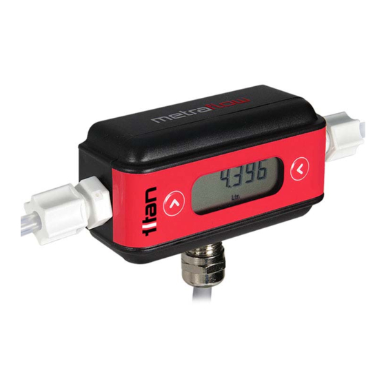
General The Titan Metraflow flow meter represents a new generation of through bore, time of flight ultrasonic flowmeters that uses patented breakthrough technology to offer a wide ranging yet accurate meter. It is ideal for any application which requires a truly non-contact high purity fluid path with a single unbroken, high quality PFA tube being the only contact material with the fluid to be measured. - Page 4 10 degrees from the horizontal may be acceptable. Due to Titan’s ultrasound algorithms used, straight upstream and downstream pipes are not necessary. It is however, good practice to install the device well away from valves, regulators elbows and other components that could cause random turbulence or gas break-out on the fluid entering or leaving the ©Titan Enterprises Ltd 2018...
- Page 5 Ground Yellow (PIN6) NPN Transistor Input/Output White (PIN7) PNP Transistor Input/Output Black (PIN8) NPN Transistor Input/Output 4-20mA Analog output (mA) Orange 0-5 or 0-10 Vdc Analog output (V) Green Analog Common Ground Analog ground ©Titan Enterprises Ltd 2018 www.flowmeters.co.uk MetraflowManual_v1219...
-
Page 6: Setup
Setup Before use, download and install Titan Interface Software from memory stick or website. The Metraflow ultrasonic flowmeter should be setup using the USB interface and a suitable computer. Below is a screen shot of the Configuration screen as it typically opens with the flowmeter connected. - Page 7 To modify the configuration click “User Settings” tab at the bottom of the screen and ensure the system is unlocked for editing When modifications are completed press the Send Settings to Meter Icon, before closing the Interface software to ensure the changes are written into the meters PCB. ©Titan Enterprises Ltd 2018 www.flowmeters.co.uk MetraflowManual_v1219...
- Page 8 This allows the user to view those tabs whilst adjusting the User Settings. The Flow Details window may be further reduced or expanded using the minimise and maximise icons respectively in the top right hand of the window ©Titan Enterprises Ltd 2018 www.flowmeters.co.uk MetraflowManual_v1219...
- Page 9 ©Titan Enterprises Ltd 2018 www.flowmeters.co.uk MetraflowManual_v1219...
- Page 10 Caution must be used however as there is no temperature/density correction. Cut Off: Flow values below this level will be set to zero. ©Titan Enterprises Ltd 2018 www.flowmeters.co.uk MetraflowManual_v1219...
- Page 11 Total DP Position: Use the drop down menu to choose the required decimal point position. If the decimal point is set too low and the display value exceeds the setting capacity the display will show “oF” ©Titan Enterprises Ltd 2018 www.flowmeters.co.uk MetraflowManual_v1219...
- Page 12 Increments go up to 5, which may take up to a minute to stabilise. External Connections In this section you can configure what functions you wish the output cables/pins to perform. ©Titan Enterprises Ltd 2018 www.flowmeters.co.uk MetraflowManual_v1219...
- Page 13 TTL levels or CMOS at 3.3V or 5.0V levels. Warning: because of the potential for conflict should the PNP output be activated accidentally, Titan Enterprises Ltd recommend a series resistor and Zener be fitted to safeguard any connected circuitry operating at logic levels.
- Page 14 The Metraflow has two options for Pulse output configuration depending on which PIN/Wire colour is chosen: PIN 6 Yellow and PIN 8 Black are both NPN pulse outputs; PIN 7 White is a PNP. ©Titan Enterprises Ltd 2018 www.flowmeters.co.uk MetraflowManual_v1219...
- Page 15 Checking this option opens up input boxes for THRESHOLD; LATCHING and INVERT. Set the Threshold to the flow value you require the transistor to operate. The logic of operation can be adjusted with the Invert check box (see left). ©Titan Enterprises Ltd 2018 www.flowmeters.co.uk MetraflowManual_v1219...
- Page 16 The Latched Alarm can be reset by a signal input on one of the other Input/Output PINS, or by pressing and holding the left hand button on the local display on the flow meter for 3 seconds. ©Titan Enterprises Ltd 2018 www.flowmeters.co.uk MetraflowManual_v1219...
- Page 17 When an analogue output is assigned the appropriate wire will then be activated: 4-20mA – Pink Wire 0-5Vdc – Red 0-10Vdc – Red 4-20mA = RED wire 0-5V = ORANGE wire ©Titan Enterprises Ltd 2018 www.flowmeters.co.uk MetraflowManual_v1219...
- Page 18 The RESULT DETAILS window below the large rate and total display shows the flow and total readings and the assignment of PIN6, 7 & 8 (yellow, white, black wires), whilst the meter is operational. ©Titan Enterprises Ltd 2018 www.flowmeters.co.uk MetraflowManual_v1219...
- Page 19 The noise affects low end performance and accuracy across the whole temperature range. The meter is calibrated at ambient temperature, typically 21 to 25°C. To zero the background noise, fill the meter with fluid under pressure at the desired metering temperature and use the Zero Null Feature: ©Titan Enterprises Ltd 2018 www.flowmeters.co.uk MetraflowManual_v1219...
- Page 20 Capture Null: This feature can be operated from the Titan Interface Software or using the Local Meter Display. Stop the flow and operate the Capture Null button in the Advanced Tab of the User Interface Software or press both buttons on the top of the meter simultaneously for 5 seconds.
- Page 21 FASTER button to adjust the measurement window a stronger signal point. A graphic is a very poor signal, ORANGE indicates a weak signal and GREEN is a good strong signal. ©Titan Enterprises Ltd 2018 www.flowmeters.co.uk MetraflowManual_v1219...
- Page 22 1 and 21. It is not an average or mean and it is designed to totally ignore one or more results. A simple example is shown below for a median value of “3”. ©Titan Enterprises Ltd 2018 www.flowmeters.co.uk MetraflowManual_v1219...
- Page 23 3 from the results either side. This filter is particularly useful at low flows where a small dip in value could drop a result below the internal cut off levels. ©Titan Enterprises Ltd 2018 www.flowmeters.co.uk MetraflowManual_v1219...
- Page 24 Once created click select and it will show in the text box. NOTE: YOU MUST CLICK THE ICON FOR A NEW FILE TO BE CREATED – TYPING IN THE TEXT BOX DOES NOT CREATE A NEW FILE Report Format: ©Titan Enterprises Ltd 2018 www.flowmeters.co.uk MetraflowManual_v1219...
- Page 25 Press the right hand button to RESET the TOTAL FLOW value. Pressing both buttons simultaneously for 5 Seconds will operate the NULL feature (see Zero Null Feature). This must be done at no flow. The display will cycle “Zero” “null” while calculating ©Titan Enterprises Ltd 2018 www.flowmeters.co.uk MetraflowManual_v1219...
-
Page 26: Technical Specification
8 Wire 1 meter flying lead (PU jacket 32x0.1 conductors) Programming PC to Meter USB lead Flow Measurement Ultrasonic Time of Flight Fluid Speed of Sound Automatic Ranging to compensate for fluid speed of sound variation Range *±1% Reading in isothermal conditions ©Titan Enterprises Ltd 2018 www.flowmeters.co.uk MetraflowManual_v1219... - Page 27 Metraflow’s internal cycle time is not adjustable, is independent of the response time and should this measurement period coincide with, or be close to, the pulsations in the flow, very large errors in the flow calculations will occur. ©Titan Enterprises Ltd 2018 www.flowmeters.co.uk MetraflowManual_v1219...
- Page 28 It is preferable to install the meter in a way that any trapped vapour can escape the flow measurement section. i.e. in a vertical line with the flow upwards. The meters are calibrated on water at ambient temperature typically 21 to 25°C. ©Titan Enterprises Ltd 2018 www.flowmeters.co.uk MetraflowManual_v1219...
-
Page 29: Troubleshooting
Purge line with high flow and restart meter Calibration incorrect Zero set at wrong temperature Remove Null by power cycling meter or using Titan Interface Software Calibration incorrect at start up. Speed of sound of fluid Check signal using Titan Interface... - Page 30 Voltage too low Increase power to meter to >15VDC Settings incorrect for Range Use Titan Interface software to range the analog output flow min and max points If you require further assistance please call +44 (0) 1935 812790 or email sales@flowmeters.co.uk...
Need help?
Do you have a question about the Metraflow 240-020 and is the answer not in the manual?
Questions and answers