
Related Manuals for Kenwood VT-173


Summary of Contents for Kenwood VT-173
- Page 1 AUTO RANGE VOLTMETER VT-173 I N S T R U C T I O N M A N U A L KENWOOD CORPORATION ©PRINTED II .PAN...
-
Page 2: Table Of Contents
C O N T E N T S G E N E R A L F E A T U R E S S P E C I F I C A T I O N S F U N C T I O N A L C O N T R O L S O P E R A T I O N A P P L I C A T I O N S M A I N T E N A N C E... -
Page 3: G E N E R A L
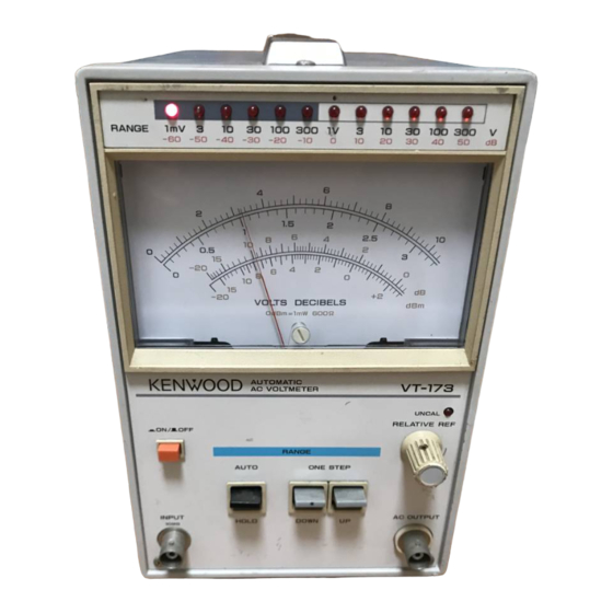
G E N E R A L F E A T U R E S The K E N W O O D E l e c t r o n i c Voltmeter V T - 1 7 3 is an Dual power differential input a m p l i f i e r s used in the absolute-mean value indication type a u t o m a t i c electronic entire circuit provide a high reliability and good... -
Page 4: S P E C I F I C A T I O N S
A n electronic circuit a u t o m a t i c a l l y selects the range 3. S P E C I F I C A T I O N S most suitable for measuring input voltage. - Page 5 [ A C output Amplifier Section] [Power Supply Section] Line voltage : 100,120,220V A C ± 1 0 % Output voltage : 1 V r m s ±20% Output resistance : 60012 ±20% 216-250 V A C , 50/60Hz Frequency response : W i t h i n ±...
-
Page 6: F U N C T I O N A L C O N T R O L S
Front Panel (see Figure 1 ) 4. F U N C T I O N A L C O N T R O L S R E F E R - D E S C R I P T I O N I D E N T I F I C A T I O N E N C E No. - Page 7 Figure 3 Figure 2 - Rear Panel V i e w . Figure 4...
-
Page 8: O P E R A T I O N
5. O P E R A T I O N Rear Panel (see Figure 2 ) R E F E R - D E S C R I P T I O N I D E N T I F I C A T I O N E N C E No. - Page 9 T o f i x the range, set the M O D E selector switch © dB Scale to H O L D position. The range immediately before The dB scale, marked w i t h d B V in general, setting the selector s w i t c h is held hereafter.
- Page 10 Then, set the M O D E selector switch on the remote control box to R E M O T E position. By t h i s , the measurement ranges of the V T - 1 7 3 can be remote- controlled w i t h the R A N G E selector on the remote...
-
Page 11: A P P L I C A T I O N S
6. A P P L I C A T I O N S point B - 4 d B in the +TQdB range. The gain f r o m point A to B is The basic use of your V T - 1 7 3 is to measure sinusoidal ( + 1 0 d B - 4 d B ) - ( - 6 0 d B + 1.5dB) = 64.5dB. - Page 12 2 ^/~2~ Root-Mean-Square a n d Peak Value Calculations • Absolute mean value= x ^ 0.9x . Y o u r V T - 1 7 3 , an voltmeter of absolute-mean value • Peak v a l u e = 0 . 9 x . indication type, reads root-mean-square values of F o r sawtooth waves, their f o r m f a c t o r is 2 / v ^ a n d...
-
Page 13: M A I N T E N A N C E
7. M A I N T E N A N C E new fuse f o r a specified value a s f o l l o w s : A C 100V, 120 : 0,2A A C 220 V , 240 V : 0.1A (1) Removing the casing (see Figure 8) 1. -
Page 14: A L I G N M E N T
A L I G N M E N T The V T - 1 7 3 is factory-adjusted precisely. However, it can be adjusted through the adjust holes on the side while being housed in the casing if necessary. F o r re- adjustment, check the supply voltage f i r s t , then follow the instructions below using a preci se I y-ca I i bra ted meas-... - Page 15 A d j u s t the frequency and output voltage of 16. Control the R E L A T I V E R E F © so t h a t the meter signal generator to 50kHz and 3V respectively reads 75mV in the 300mV range.
-
Page 16: C A U T I O N S F O R U S E
M O N I T O R O U T connector. A p r o d u c t o l KENWOOD CORPORATION 7. Be sure to use the H O L D ( m a n u a l ) mode to measure non-sinusoidal wave voltage.
Need help?
Do you have a question about the VT-173 and is the answer not in the manual?
Questions and answers