Advertisement
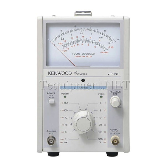
AC VOLTMETER
VT-181/VT-181E
SERVICE MANUAL
FRONT PANEL
VT-181 : (A63-0301-08)
VT-181E : (A63-0316-08)
SIDE FRAME
(A13-2254-08)
PUSH KNOB
(K24-3015-08)
HANDLE
HANDLE COVER : (B09-0410-08)
RUBBER FOOT
(J02-0543-08)
KENWOOD TMI CORPORATION
© 1998-4/B51-1132-00 (K/K)
: (K01-0564-08)
KNOB
(K21-0959-08)
RORARY KNOB
(K21-0961-08)
Advertisement
Table of Contents

Related Manuals for Kenwood VT-181


Summary of Contents for Kenwood VT-181
- Page 1 AC VOLTMETER VT-181/VT-181E KENWOOD TMI CORPORATION SERVICE MANUAL © 1998-4/B51-1132-00 (K/K) HANDLE : (K01-0564-08) HANDLE COVER : (B09-0410-08) FRONT PANEL VT-181 : (A63-0301-08) VT-181E : (A63-0316-08) SIDE FRAME (A13-2254-08) KNOB PUSH KNOB (K21-0959-08) (K24-3015-08) RORARY KNOB (K21-0961-08) RUBBER FOOT (J02-0543-08)
-
Page 2: Table Of Contents
VT-181/VT-181E WARNING The following instructions are for use by qualified personnel only. To avoid electric shock, do not perform any servicing other than contained in the operating instructions unless you are qualified to do so. CONTENTS SPECIFICATIONS ......................3 SAFETY ..........................4 CIRCUIT DESCRIPTION ....................5... -
Page 3: Specifications
VT-181/VT-181E SPECIFICATIONS Item VT-181 VT-181E Meter Section Measurable Voltage 1mV to 300mV in 12 ranges:1,3, 0.3mV to 100mV in 12 ranges:0.3, 10,30,100,300mV,1,3,10,30, 1,3,10,30,100,300mV,1,3,10, 100,300V full scale. 30,100V full scale. -80 to +50dB(0dB=1V) -90 to +40dB(0dB=1V) -80 to +52dBm(0dBm=1mW at 600Ω) -90 to +42dBm(0dBm=1mW at 600Ω) -
Page 4: Safety
VT-181/VT-181E SAFETY SAFETY Line fuse Before connecting the instrument to a power source, care- The fuse holder is located on the rear panel and contains fully read the following information, then verify that the the line fuse. Verify that the proper fuse is installed by proper power cord is used and the proper line fuse is replacing the line fuse. -
Page 5: Circuit Description
VT-181/VT-181E CIRCUIT DESCRIPTION The voltage or sentence in parenthes is applicable in case of the "VT-181E". In studying the operation of each circuit in voltmeter please refer to "BLOCK DIAGRAM". General 5) Main Amplifier A Signal voltage to be measured, which is input from the... - Page 6 INPUT CH1. PC BOARD OUTPUT-1 IMPEDANCE 1st ATT 2nd ATT 3rd ATT MAIN AMP OUTPUT AMP CONVERTER GAIN CONTROL RELATIVE REF ROTARY SW CONTROL METER ABSOLUTE MEAN VALUE DET AC 100V/120V/220V/230V 50/60Hz DC5V POWER POWER SUPPLY TRANSFORMER DC-5V POWER ON/OFF...
-
Page 7: Adjustment
VT-181/VT-181E ADJUSTMENT To obtain the best performance, periodically calibrate the Test Equipment Model Maker unit. Sometimes, only one mode need be calibrated, while at Calibrator 5100B FLUKE other times, all modes should be calibrated. When one CR Oscillator AG-203 KENWOOD... - Page 8 VT-181/VT-181E ADJUSTMENT ITEM ADJUSTMENT POINT PROCEDURE 1V range VR101 RANGE: 1V 1) Input 1kHz (or 400 Hz), 1 Vrms sine wave, and set the pointer to 10.0 V of the 0- 10 scale. Check that the variable range is less than 98% and more than 102% with respect to 10.0 (full-scale).
-
Page 9: Parts List
Teile ohne Parts No. werden nicht geliefert. Teile ohne Parts No. werden nicht geliefert. Add- Add- Ref. No Parts No. Description Ref. No Parts No. Description ress ress VT-181 (Y80-2050-00) VT-181E (Y80-2060-00) A01-4087-08 CASE;TOP A01-4087-08 CASE;TOP A01-4088-08 CASE;BOTTOM A01-4088-08 CASE;BOTTOM A13-2254-08 FRAME... -
Page 10: Parts List (Electrical)
* New Parts * New Parts Parts without Parts No. are not supplied. Parts without Parts No. are not supplied. Les articles non mentionnes dans le Parts No. ne sont pas fournis. Les articles non mentionnes dans le Parts No. ne sont pas fournis. Teile ohne Parts No. - Page 11 * New Parts * New Parts Parts without Parts No. are not supplied. Parts without Parts No. are not supplied. Les articles non mentionnes dans le Parts No. ne sont pas fournis. Les articles non mentionnes dans le Parts No. ne sont pas fournis. Teile ohne Parts No.
- Page 12 * New Parts * New Parts Parts without Parts No. are not supplied. Parts without Parts No. are not supplied. Les articles non mentionnes dans le Parts No. ne sont pas fournis. Les articles non mentionnes dans le Parts No. ne sont pas fournis. Teile ohne Parts No.
- Page 13 * New Parts * New Parts Parts without Parts No. are not supplied. Parts without Parts No. are not supplied. Les articles non mentionnes dans le Parts No. ne sont pas fournis. Les articles non mentionnes dans le Parts No. ne sont pas fournis. Teile ohne Parts No.
- Page 14 IC, FIXED VOLTAGE REGULATOR U103 LM7905 IC, FIXED VOLTAGE REGULATOR VR101 R12-1545-05 RES. SEMI FIXED 1/10W VR102 R12-0575-05 RES. SEMI FIXED 1/10W VT-181 RANGE UNIT (W02-2365-08) J73-0540-08 PCB(UNMOUNTED) E40-7609-08 CONNECTOR S60-0628-08 ROTARY SWITCH S101 VT-181E RANGE UNIT (W02-2366-08) J73-0540-08 PCB(UNMOUNTED) E40-7609-08...
-
Page 15: Schematic Diagram
VT-181 SCHEMATIC DIAGRAM... - Page 16 VT-181E SCHEMATIC DIAGRAM...
- Page 17 VT-181 SCHEMATIC DIAGRAM...
- Page 18 VT-181E SCHEMATIC DIAGRAM...
- Page 19 VT181 VT181E...
-
Page 21: Board
PC BOARD (Component side view) RANGE UNIT PANEL UNIT(W02-2368-08) (W02-2365-08/W02-2366-08) Pattern side view Pattern side view MAIN UNIT(W02-2355-08/W02-2356-08) Refer to the schematic diagram for the values of resistors and capacitors. - Page 22 VT-181/VT-181E A product of KENWOOD TMI CORPORATION 1-16-2, Hakusan, Midori-ku, Yokohama City 226, Japan...
Need help?
Do you have a question about the VT-181 and is the answer not in the manual?
Questions and answers